| Author |
Message |
Fernando

Joined: Dec 30, 2006
Posts: 286
Location: Barcelona & Emporda, Spain
|
|
|
Back to top
|
|
 |
Fernando
Joined: Dec 30, 2006
Posts: 286
Location: Barcelona & Emporda, Spain
|
|
|
Back to top
|
|
|
Grumble

Joined: Nov 23, 2015
Posts: 1320
Location: Netherlands
Audio files: 30
|
 Posted: Wed Apr 13, 2022 2:58 pm Post subject: Posted: Wed Apr 13, 2022 2:58 pm Post subject:
|
  |
|
One remark:
R4 with the label Fmax, if that is a potentiometer, it is good practice to connect the wiper to the pin that is not connected right now (pin 1 in your drawing).
The reason for this is that when your pots get a little older and starts to wear you always have at least the max impedance of the potentiometer (1k in this case) between the connections and not infinit impedance.
_________________
my synth |
|
|
Back to top
|
|
|
Fernando
Joined: Dec 30, 2006
Posts: 286
Location: Barcelona & Emporda, Spain
|
| Posted: Wed Apr 13, 2022 3:05 pm Post subject:
|
|
|
Thank you! they are all trimmers (pots are in wiring page)
The one with one pin unconnected is as in original schematic
_________________
Fer
. |
|
|
Back to top
|
|
|
AlanP
Joined: Mar 11, 2014
Posts: 746
Location: New Zealand
Audio files: 41
|
| Posted: Thu Apr 14, 2022 2:29 pm Post subject:
|
|
|
| Interesting. How dependant is this circuit on specific transistors? (I've built the 258 VCO before, and it is really, really dependant on selection of the sine waveshaping FET.) |
|
|
Back to top
|
|
|
Fernando
Joined: Dec 30, 2006
Posts: 286
Location: Barcelona & Emporda, Spain
|
| Posted: Thu Apr 14, 2022 6:26 pm Post subject:
|
|
|
| AlanP wrote: | | Interesting. How dependant is this circuit on specific transistors? (I've built the 258 VCO before, and it is really, really dependant on selection of the sine waveshaping FET.) |
Just read the two links I posted and notes on the schematic. It's not Raiders of the Lost Ark kinda mission :D
For Q15 (N channel JFET) it is important to select one with Idss 0.5mA, as schematic specifies (258 need it in the range 0.8-1.1mA).
It's goal is to saturate the incoming triangle wave to form the sine wave (same as in Buchla 258, EN76 VCO and many others)
I found many usable candidates (.5) among 80s 90s J201, but I find that more recent J201 start at higher Idss, .9 or so (good for 258)
I also found many at .5mA within 2SK118, which is easy to find. Look for range "R" (= Idss 0.3-0.75).
I don't have any J204 or 2N4338, but they should provide specimens at 0.5, since specs say 0.2mA minimum (note that if you get a FET with specified min Idss 0.5, it will be pretty difficult to find some at 0.5! You better try with those spec. at min. Idss 0.2-0.3)
Mike Peake found some 2N4339 within range, but there should be more chances with 4338.
That's why I suggest J201, 2SK118, J204, 2N4338 on the notes, but there are many other candidates.
The $12 chinese transistor testers are great (key maybe) for this, a must-have tool!
For Q7 (P channel JFET) I'm not sure what spec and range are key, but both 2N5020 and 2N5460 work well (2607, 2608 and 5033 should work too).
Mike Peake had success with 5020 ($12-14), Pre55ure had success with 5460 ($0.50)
For the rest of transistors (pairs and singles) 2N3904/06, BC550/560, etc. are fine I you don't have 2N4916 and 2N3565.
You can use Ian Fritz transistor matcher circuit for pairs.
Or you can just use transistors of the same batch and they will, very probably, be much better matched than the original, since MD708B (Q1-Q2) is a dual NPN with pretty poor matching specs anyway (10mV IIRC)
With Ian's circuit one can match them down to 50uV without effort. By using same batch pairs I guess they'll be within 1mV or so.
Again, see Peake's blog.
_________________
Fer
.
Last edited by Fernando on Wed May 11, 2022 10:15 am; edited 4 times in total |
|
|
Back to top
|
|
|
Peake

Joined: Jun 29, 2007
Posts: 1113
Location: Loss Angeles
Audio files: 3
|
| Posted: Wed Apr 27, 2022 2:52 am Post subject:
|
|
|
2N5460, definitely.
_________________
We are selling emotions, there are no emotions in a grid. -mwagener
"IC 741. Sometimes you don't want fidelity." -Small Bear Electronics Catalog |
|
|
Back to top
|
|
|
vladosh

Joined: Aug 02, 2010
Posts: 679
Location: macedonia
Audio files: 51
|
| Posted: Mon Nov 14, 2022 6:14 am Post subject:
|
|
|
Thanks for sharing this ,i've built over 10 x 258 VCO's from a layout that is available here on forum and the last 2 times i couldn't get it to work ,and gave up ,and now it's me without a proper Buchla VCO ,this should do very nice ,i will share a PCB layout for this if it's ok ,thanks a lot
cheers
_________________
http://synthacks.blogspot.com/ шематикс |
|
|
Back to top
|
|
|
Fernando
Joined: Dec 30, 2006
Posts: 286
Location: Barcelona & Emporda, Spain
|
| Posted: Mon Nov 14, 2022 4:01 pm Post subject:
|
|
|
Well this layout is already done
I posted it in case people want some pcbs (I posted my pcb design on another thread. It is the original circuit intact plus a CV mixer and an output amp)
But of course, do what you wish
In any case it's nice to have a clear schematic now : )
_________________
Fer
. |
|
|
Back to top
|
|
|
Fernando
Joined: Dec 30, 2006
Posts: 286
Location: Barcelona & Emporda, Spain
|
| Posted: Mon Nov 14, 2022 4:23 pm Post subject:
|
|
|
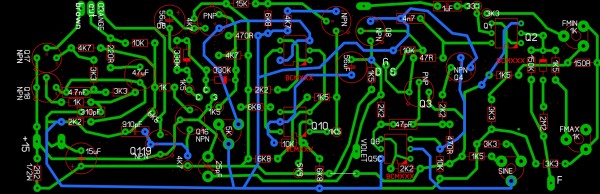
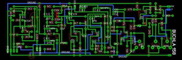
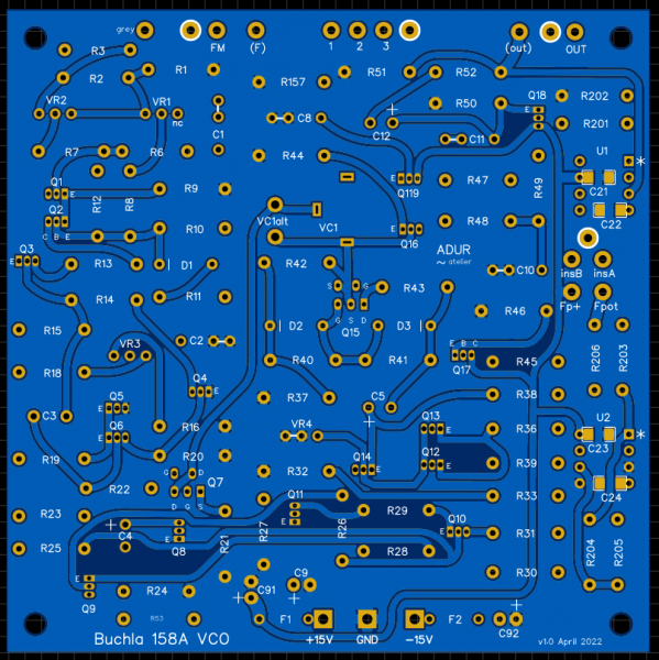
Not the last version I have, but it's illustrative (10x10cm pcb) :
PM if interested
| Description: |
|
| Filesize: |
359.79 KB |
| Viewed: |
237 Time(s) |
| This image has been reduced to fit the page. Click on it to enlarge. |
|
| Description: |
|
| Filesize: |
299.26 KB |
| Viewed: |
225 Time(s) |
| This image has been reduced to fit the page. Click on it to enlarge. |
|
_________________
Fer
. |
|
|
Back to top
|
|
|
vladosh
Joined: Aug 02, 2010
Posts: 679
Location: macedonia
Audio files: 51
|
|
|
Back to top
|
|
|
Fernando
Joined: Dec 30, 2006
Posts: 286
Location: Barcelona & Emporda, Spain
|
| Posted: Tue Nov 15, 2022 6:40 am Post subject:
|
|
|
Excellent!
Just to clarify: my pcb lets you choose between the original power scheme of +15V direct to 3 transistors and the rest of the circuit thru R53 and C9 (as I understand you did) and a modern power scheme (power in to ferrite beads and 10uF)
Additionally, my pcb let you choose between original freq control INT/EXT and a modern CV mixer that lets you have both the freq pot and as many inputs you want, all with bipolar attenuators.
Also my pcb have an output amp to adapt the original 1V RMS (2.83Vpp) to 5Vpp, 10Vpp or what you like.
I did all film caps with multi-size footprints and FETs (Q7, Q15) with a footprint that let you use many different devices.
I did a 100x100mm pcb so it can be used in small systems (Eurorack) or larger systems (Serge, Buchla, MOTM, etc). Thru plated holes, etc., very good quality
_________________
Fer
. |
|
|
Back to top
|
|
|
vladosh
Joined: Aug 02, 2010
Posts: 679
Location: macedonia
Audio files: 51
|
| Posted: Tue Nov 15, 2022 7:12 am Post subject:
|
|
|
i was just excited to see a well documented buchla module ,to be honest i am not so certain that i will build it ,tho i want to ,i hope i will ,about those add ons and mods ..you are right it's prolly better way to fit into modular ,i should maybe make some high gain amps to boost the signal if it's quiet ..in the end i will be so happy if it works ,maybe to add that 156 processor ,anyway ,i believe there might be some negative voltage here and there in my modular ,i wonder how this VCO behaves on negative voltage ,it's descrete i guess it won't do any harm ..even so ..it is still worth building ,thanks
_________________
http://synthacks.blogspot.com/ шематикс |
|
|
Back to top
|
|
|
Fernando
Joined: Dec 30, 2006
Posts: 286
Location: Barcelona & Emporda, Spain
|
| Posted: Tue Nov 15, 2022 8:20 am Post subject:
|
|
|
of course it worths! it is a lovely discrete VCO!!! :D
_________________
Fer
. |
|
|
Back to top
|
|
|
vladosh
Joined: Aug 02, 2010
Posts: 679
Location: macedonia
Audio files: 51
|
| Posted: Fri Nov 18, 2022 1:39 am Post subject:
|
|
|
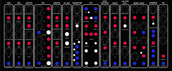
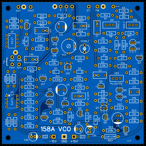
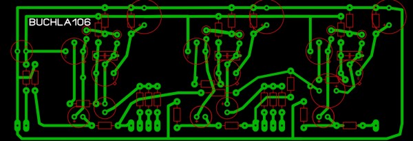
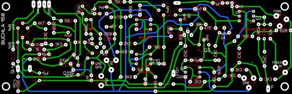
i fixed it up a bit and shared on my blog ,i hope it's ok ,also did a layout for Buchla 106 https://synthacks.blogspot.com/2022/11/buchla-158.html , i wonder if i ever get to building this stuff .. more then 10yrs of building synths so often it is hard to sit down and do some soldering ,i wish i could get some window size Modcan and clean up my room
| Description: |
|
| Filesize: |
383.11 KB |
| Viewed: |
226 Time(s) |
| This image has been reduced to fit the page. Click on it to enlarge. |
|
| Description: |
|
| Filesize: |
817.53 KB |
| Viewed: |
255 Time(s) |
| This image has been reduced to fit the page. Click on it to enlarge. |
|
_________________
http://synthacks.blogspot.com/ шематикс |
|
|
Back to top
|
|
|
Fernando
Joined: Dec 30, 2006
Posts: 286
Location: Barcelona & Emporda, Spain
|
| Posted: Fri Nov 18, 2022 3:14 am Post subject:
|
|
|
nice!
_________________
Fer
. |
|
|
Back to top
|
|
|
vladosh
Joined: Aug 02, 2010
Posts: 679
Location: macedonia
Audio files: 51
|
| Posted: Fri Nov 18, 2022 3:49 am Post subject:
|
|
|
i so want to make some other buchla layout but not knowing what schematic is correct ..is hard .
_________________
http://synthacks.blogspot.com/ шематикс |
|
|
Back to top
|
|
|
vladosh
Joined: Aug 02, 2010
Posts: 679
Location: macedonia
Audio files: 51
|
|
|
Back to top
|
|
|
Fernando
Joined: Dec 30, 2006
Posts: 286
Location: Barcelona & Emporda, Spain
|
| Posted: Tue Nov 22, 2022 12:37 pm Post subject:
|
|
|
very cool
_________________
Fer
. |
|
|
Back to top
|
|
|
vladosh
Joined: Aug 02, 2010
Posts: 679
Location: macedonia
Audio files: 51
|
|
|
Back to top
|
|
|
Fernando
Joined: Dec 30, 2006
Posts: 286
Location: Barcelona & Emporda, Spain
|
| Posted: Mon Nov 28, 2022 1:27 pm Post subject:
|
|
|
nice! Sauce of Uncle is a good option IMHO
_________________
Fer
. |
|
|
Back to top
|
|
|
vladosh
Joined: Aug 02, 2010
Posts: 679
Location: macedonia
Audio files: 51
|
| Posted: Wed Dec 07, 2022 6:59 am Post subject:
|
|
|
What transitor testers are you using folks ? J-Fets have been an issue since i got some fakes yrs ago and i can't always order from trusted sellers . I just received a tester from Ali , but when i plug in a P Channel Fet it says it's an NPN ,now there are some other measurements there but it does not identify it's pins ,the J112 or 201 is measured like resistor ,some 50 ohms or so ,not sure what it means ,anyone ?
Thanks
_________________
http://synthacks.blogspot.com/ шематикс |
|
|
Back to top
|
|
|
Fernando
Joined: Dec 30, 2006
Posts: 286
Location: Barcelona & Emporda, Spain
|
| Posted: Wed Dec 07, 2022 7:44 am Post subject:
|
|
|
I use the usual China-made clone of the originally open source ATMEGA project. It costs around $12 and it's fantastic.
I also have a Meterman 37XR, which can measure capacitance and inductance in addition to the usual readings.
There is always a problem with JFETs with high Idss (let's say >20mA). Transistor tester says it is an UJT or whatever. For those few you need to test them in a real circuit. I think I have a couple of test circuits diagrams, I'll post them if I find them.
I have some 2N4339 in TO-18, Idss specs are 0.5-1.5mA, readings are 10 to 30mA. In this case I suspect they may be fakes, for instance. But you can't never be sure with FETs! So it's better to test them on a real circuit.
But 2N4856 Idss specs are 50mA minimum. I accept the tester gets confused with this one.
Maybe this happens because this testers supply only 6mA for most readings.
----> Anyway this topic deserves it's own thread. Open a new thread?
_________________
Fer
.
Last edited by Fernando on Wed Dec 07, 2022 8:07 am; edited 1 time in total |
|
|
Back to top
|
|
|
Fernando
Joined: Dec 30, 2006
Posts: 286
Location: Barcelona & Emporda, Spain
|
|
|
Back to top
|
|
|
vladosh
Joined: Aug 02, 2010
Posts: 679
Location: macedonia
Audio files: 51
|
| Posted: Wed Dec 07, 2022 8:50 am Post subject:
|
|
|
i don't know maybe there is obvious way to understand , maybe when i plug in a J112 and it says pin1 and pin2 are resistor of 50ohms ,maybe pin1 and pin2 are source and gate ,and there is some formula to calculate everything from say 56.71 ohms but i never really cared about math to be honest,i was expecting to plug in a jfet (and i tried good transistors) and it shows me what is source ,gate and drain ,and something to understand what rating is the transistor ..guess it's not that simple for 12$ ..it's not about the money ,it's just that it's sort of useless to me now ,i'll just be careful where i buy the transistors and maybe i dunno build my own tester
_________________
http://synthacks.blogspot.com/ шематикс |
|
|
Back to top
|
|
|
|

 Forum index » DIY Hardware and Software