| Author |
Message |
bigtex

Joined: Mar 30, 2006
Posts: 323
Location: Cupertino, California
|
 Posted: Fri May 12, 2006 7:00 pm Post subject:
Three-way crossfader on a single potentiometer? Posted: Fri May 12, 2006 7:00 pm Post subject:
Three-way crossfader on a single potentiometer? |
  |
|
I've got a few different ideas that would work a lot better if I could figure out how to do this one thing: fade continuously between three sources using only one control. Take, for example, a VCA that can go from exponential to linear to logarithmic with the turn of a knob. That would be really cool! Or even just crossfading between three different audio sources, such as lowpass, bandpass, and highpass. All under voltage control. I'd quite like that.
I'm trying to figure out how I could set up a circuit so that a potentiometer (likely with a center detent, to make it more intuitive) could control such a circuit. 50% of it would crossfade between signals 1 and 2, and the other 50% would crossfade between signals 2 and 3.
I guess I could implement this by having a comparator switch between the two halves (1 to 2, 2 to 3) at the crossover point (probably 0 volts). I'd then need to have one pair of VCAs that responded to positive control voltages and another pair of VCAs that responded to negative control voltages. The only thing that worries me is having any type of glitch at the corssover point. If I were feeding a wave in to control it, and it had a little dropout or pop when signal 2 was at it's loudest, that wouldn't sound good at all.
I might be able to accomplish the same thing by using diodes to create two parallel half-wave rectifiers to send the positive CV to one half and the negative CV to the other half, but I'd definitely get a crossover glitch that way. Easier to implement, but worse result...
I've also thought about using a dual-gang potentiometer, but that probably wouldn't simplify it any.
Any ideas? Has this been done before? I did some searching, but I wasn't exactly sure what to search for. I think some Blacet modules might do something like this, but I won't know for at least a few weeks (when I'll have the money to make my big Blacet order!)
The Filthy Filtre module has this feature:
"VC mode select: switch or morph (LP, BP, HP, All Pass)!"
So I guess that might be like what I'm talking about... but I don't want to rip off Blacet's way of doing it if that is the case.... |
|
|
Back to top
|
|
 |
bigtex
Joined: Mar 30, 2006
Posts: 323
Location: Cupertino, California
|
| Posted: Fri May 12, 2006 7:52 pm Post subject:
|
|
|
I just couldn't leave that one alone. I started sketching stuff out, and I think this just might do it.
This is a high level block diagram, and certainly not a complete schematic:

I need to work out a proper schematic, and then try it out! |
|
|
Back to top
|
|
|
bigtex
Joined: Mar 30, 2006
Posts: 323
Location: Cupertino, California
|
| Posted: Fri May 12, 2006 8:10 pm Post subject:
|
|
|
Oh, a little explanation might be in order... first of all, the triangles with + and - in them are non-inverting and inverting amplifiers (or buffers) respectively.
So, starting at the left:
Potentiometer delivers a voltage that goes three ways (oh, I might need to put a buffer there to feed those three paths...)
The top one has a diode that will only pass the positive voltages (oh, did I reverse my diodes...??). Those positive voltages will be used to control the amplifier for Signal 1.
The bottom one has a diode that will only pass the negative voltages (yeah, I think I reversed my diodes...). Those negative voltages are then inverted by the inverting amplifier to deliver a positive control voltage to the amplifier for signal 3.
The middle path is kind of complicated. First, the voltage is full-wave rectified. This way, positive or negative, the magnitude of the voltage (regardless of the polarity) will ba passed along. Next, I sum the output of this with -10V. I do this to invert the magnitude of the voltage (different from inverting the polarity!). I invert the polarity of this as well, to make it positive again. So what was previously a voltage variable over a range of -10 to +10 I have turned into a 0 to +10V control voltage that goes high when the input is close to zero and goes low when the input is close to it's maximum.
Kind of a strange way to do it, but I think it just might do the trick. The only problem is that I'm still losing +/-0.7V around zero by full-wave rectifying this. The design for the odd way of full-wave rectifying was pulled from this page. I might change that method in the future as well.
So I think this is a good starting point. I might be able to use a capacitor to smooth out any glitches on the CV for Signal 2's amplifier. But, then, that would also slow down the response and make this less usefull for high-speed crossfading.
Can anybody improve on this or point out where I'm way wrong? |
|
|
Back to top
|
|
|
toppobrillo

Joined: Dec 10, 2005
Posts: 766
Location: oakland, ca
G2 patch files: 1
|
| Posted: Fri May 12, 2006 8:47 pm Post subject:
|
|
|
hey, maybe look at j.haible's interpolating scanner for an idear. oh by the way, if my car sells tommorrow, i'll be headed your way perrty soon man. i guess we [my friend carrie and i] are looking at a place in oakland. alittle cheaper. exciting! but i will be without all my tools, equipment, records, books, and well, pretty much everything non-essential for a good while. boo to that.
josh |
|
|
Back to top
|
|
|
bigtex
Joined: Mar 30, 2006
Posts: 323
Location: Cupertino, California
|
| Posted: Sat May 13, 2006 1:10 pm Post subject:
|
|
|
Once again, I am dumbfounded by Jurgen's brilliance. I'd had a vague notion of having triangular amplitude envelopes like that, but I hadn't taken it to the next level. He's got eight triangular envelopes, each within a 1V range, all under the control of one potentiometer. Genius! I'm still trying to wrap my head around how his circuit is actually accomplishing that. Doing it all within a positive voltage range does eliminate the 0V crossover glitch from diodes, for sure. I'd still like to cobble together my own vresion of this, just for the sake of it, but Mr. Habile's ideas will help me immensely.
Don't feel so bad about being in Oakland instead of SF. Oakland has some pretty cool stuff. I know a lot of interesting people in Oakland. Give me a holler if you do make it. |
|
|
Back to top
|
|
|
toppobrillo
Joined: Dec 10, 2005
Posts: 766
Location: oakland, ca
G2 patch files: 1
|
| Posted: Sat May 13, 2006 10:40 pm Post subject:
|
|
|
hey, i will be starting on my own 4x thing like this too, soon, with a quad vca from AD. i'll let ya know what progress i make.
yeah i think oakland will be fine at least until i figure out whats where, etc. transportation is important, so i want good access. ill probably get a bike as soon as i arrive. im so out of shape! hah that will change fast- i remember a couple years ago i was riding like around 10 miles a day- and that was when i still smoked cigarettes. i heard that you can actually get a DUI on a bicycle! i guess i was lucky...
josh |
|
|
Back to top
|
|
|
piedwagtail

Joined: Apr 15, 2006
Posts: 297
Location: shoreditch
Audio files: 3
|
|
|
Back to top
|
|
|
bigtex
Joined: Mar 30, 2006
Posts: 323
Location: Cupertino, California
|
| Posted: Sun May 14, 2006 4:34 pm Post subject:
|
|
|
| Hey, that one's good, too! Thanks! |
|
|
Back to top
|
|
|
Scott Stites
Janitor


Joined: Dec 23, 2005
Posts: 4127
Location: Mount Hope, KS USA
Audio files: 96
|
| Posted: Sun May 14, 2006 7:25 pm Post subject:
|
|
|
I've long wanted to try the Exquisite Corpse - note the advantage of having bar or dot mode. Spiffirino.
Tex, you might want to check out Jim Patchell's writings on the ideal diode - it's along the lines of JH's Interpolating Scanner. Rene Schmitz hosts a copy of it here:
http://www.uni-bonn.de/~uzs159/diode_tutorial/index.html
I think you'll get all kinds of groovy ideas from it.....
Cheerio,
Scott |
|
|
Back to top
|
|
|
bigtex
Joined: Mar 30, 2006
Posts: 323
Location: Cupertino, California
|
| Posted: Sun May 14, 2006 9:16 pm Post subject:
|
|
|
| BRILLIANT!! |
|
|
Back to top
|
|
|
toppobrillo
Joined: Dec 10, 2005
Posts: 766
Location: oakland, ca
G2 patch files: 1
|
| Posted: Sun May 14, 2006 9:52 pm Post subject:
|
|
|
| coolyo! |
|
|
Back to top
|
|
|
toppobrillo
Joined: Dec 10, 2005
Posts: 766
Location: oakland, ca
G2 patch files: 1
|
|
|
Back to top
|
|
|
bigtex
Joined: Mar 30, 2006
Posts: 323
Location: Cupertino, California
|
| Posted: Mon May 15, 2006 1:21 am Post subject:
|
|
|
Oh, that's awesome. Not really even all that elaborate, either. I've been looking for a simple-ish circuit that does just that.
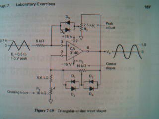
What detail does that book give on the "carrier adjust" knob. The word carrier makes me think of some kind of high frequency modulation, but I doubt that is what is going on in that circuit... |
|
|
Back to top
|
|
|
toppobrillo
Joined: Dec 10, 2005
Posts: 766
Location: oakland, ca
G2 patch files: 1
|
| Posted: Mon May 15, 2006 2:13 am Post subject:
|
|
|
sorry kinda blurry huh. starting with the top, the trims are: peak adj., center slopes, and crossing slope.
yeah i guess not too elaborate. i guess what i meant was articulate, with three trimmers... fancy. |
|
|
Back to top
|
|
|
zipzap
Joined: Nov 22, 2005
Posts: 559
Location: germany
Audio files: 24
|
| Posted: Mon May 15, 2006 3:07 am Post subject:
|
|
|
| cool circuit! Some questions i have: Is it important which diodes and opamp i use? Are the trimmers r1,2 going to ground or -15v? |
|
|
Back to top
|
|
|
piedwagtail
Joined: Apr 15, 2006
Posts: 297
Location: shoreditch
Audio files: 3
|
| Posted: Mon May 15, 2006 9:01 am Post subject:
|
|
|
ground,Zipzap,if the illustrator uses a black arrow for the -15V,under the CA3140.
i've been following the tutorials here
http://users.ece.gatech.edu/~lanterma/ece4803/
and he makes a mess for downward arrow identification
but i found the klein schmit trigger in the standard triangle core interesting.
and his exposition of the buchla deadband is informative.
broadband only,files are >140Mb.
Robert |
|
|
Back to top
|
|
|
bigtex
Joined: Mar 30, 2006
Posts: 323
Location: Cupertino, California
|
| Posted: Mon May 15, 2006 9:27 am Post subject:
|
|
|
| Wow. Even more incredible resources I was unaware of. This thread is awesome! Thanks guys! |
|
|
Back to top
|
|
|
zipzap
Joined: Nov 22, 2005
Posts: 559
Location: germany
Audio files: 24
|
| Posted: Mon May 15, 2006 3:06 pm Post subject:
|
|
|
| exactly! Amazing! |
|
|
Back to top
|
|
|
toppobrillo
Joined: Dec 10, 2005
Posts: 766
Location: oakland, ca
G2 patch files: 1
|
| Posted: Mon May 15, 2006 5:44 pm Post subject:
|
|
|
hey, yeah what robert said. nah, you could use others like tl08_ or whatever. diodes are 1n914.
in the illustration, it's shown that a 1.4v p-p tri input will result in a 2v p-p sine with the values shown. |
|
|
Back to top
|
|
|
|

 Forum index » DIY Hardware and Software