| Author |
Message |
Scott Stites
Janitor


Joined: Dec 23, 2005
Posts: 4127
Location: Mount Hope, KS USA
Audio files: 96
|
 Posted: Sun Oct 01, 2006 8:12 am Post subject: Posted: Sun Oct 01, 2006 8:12 am Post subject:
|
  |
|
Thanks, guys. Sometimes when the Klee goes off on a tangent, I just want to stand in front of the breadboard with my lighter held up....
| Quote: | | There was so much shady space under those 4034s I just couldn't say no. It does make sense though, there is always at least two verticals under a chip, and there's no reason not to run the power in on them, just have to remember to put those links in before your IC sockets. |
Oh, yes, I do that all the time. The space those wide bodies takes is obscene.
Jan, I checked the datasheet - at the end they have a standard package description (must be standard, because the description shows a lens on the top of the IC, which the CD4034 doesn't have). Weird thing is, they list the dimensions for wide and narrow, but they're both the same dimensions - ????.
One thing that really helps in a build that has a number of CMOS ICs is getting those sockets that have the 0.1 uF supply cap built into them - those are really nice. They actually have a cap tied between the supply pin and the ground pin. You notice each Klee IC has a 0.1 uF on the supply pin - this would eliminate having to put all of those on the board for the CMOS parts.
| Quote: | | I'm trying to work out now how to consolidate some space so I can fit that last 4050 hex buffer on. |
Those 4050 pinouts are *hideous* - I couldn't find any really good method to tie them to everything else without invoking a rats nest of one shape or another.
I think the Model 2 will be complete (finally) this weekend. I have yet to test the reduced parts count Bus Gate, put in the switch matrix for the attenuator, and settle on the control voltage mixer.
The control voltage mixer design is just a matter of what to keep and what to throw out. Having three unique outputs turns it into a Kitchen Sink junky's nirvana/nightmare. Most of the samples I've posted use the keyboard to alternate pitch on at least one voice - like in that last sample, I'll hit a low note on the keyboard, let that play a while, then hit a high note - it breaks the monotony of a sequence hammering over and over. I've been doing that by just controlling a VCO with both the Klee and the keyboard. It would be nice if the Klee had a V/Oct input - that would expedite things in a patch considerably. The ARP 1601 had such a control input. Not only is it good for keyboards, but it also allows a second sequencer to vary the sequence even further.
The second option is a modulation input - it's really nice to modulate one voice while leaving another voice unmodified - again, on the first two portions of the sample, you can hear one voice has vibrato (the 'lead voice') while the backing voice has none.
And, finally, an offset control would be quite expedient. Using the attenuator, the sequences maintain a musical interval as one switches through the ranges, and that interval 'expands' with every step up. A heavily programmed Klee sequence is good until one gets into the 1V or 2V ranges max, then the mixer (and one's ear's frequency response) runs out of range . All of those voltages add up, remember, and 8 pots set to 2V max, for example, will hit 16V, out of the realm of the power supply. Anyway, while switching through, the general sequence itself will get higher in pitch - an offset would be handy to globally lower the overall voltage if one wanted to try the same sequence in a lower register.
Obviously, each output should have portamento available as well. Right now, it's a simple linear lag circuit that you've been hearing, and I'm sticking with that - more pleasing to my ear than expo when using the Klee.
All of this is easy to implement, but my fear is the front panel overhead, as usual.
Cheers,
Scott |
|
|
Back to top
|
|
 |
Coriolis

Joined: Apr 11, 2005
Posts: 616
Location: Stilling, Denmark
|
| Posted: Sun Oct 01, 2006 8:51 am Post subject:
|
|
|
Man, I would love to see a quick example gif of a frontpanel for this thing, or for differences between Klee 2 and 3.
I mean; I get that it's probably going to be 16 pots and three outputs (A, B, A+B), but beyond that...? Oh, and some cv-inputs, an external clock input.
Maybe just a quick list of ins, outs, pots, switches, functions?
Maybe I should just let you finish this thing! 
C |
|
|
Back to top
|
|
|
Scott Stites
Janitor
Joined: Dec 23, 2005
Posts: 4127
Location: Mount Hope, KS USA
Audio files: 96
|
| Posted: Sun Oct 01, 2006 10:01 am Post subject:
|
|
|
Coriolis,
First of all, there are four rows of '16'
16 LEDs
16 Voltage Pots
16 Pattern Switches
16 Bus Switches
LEDs probably should be right above the pattern switches, with the pots right below the pattern switches, and the gate bus switches below the pots.
Control section will have a momentary load switch, a momentary step switch, and a toggle Bus 1 reload switch. In addition to that, there is a toggle 8X2/16X1 switch, a toggle Random/pattern switch, a random reference pot and a random source level pot. I haven't included it on the schematics, but a simple toggle switch to prevent the clock from shifting the sequence would be handy - if one has a sequence acquired through random methods, and wants to use that same sequence at a later time, one stops the sequence and flips the pattern switches to match the LEDs. Right now the only way to stop the pattern from shifting is to disconnect the clock source. This switch could be wired entirely on the panel.
Control inputs are clock, load, and random signal.
Control indicators are clock LED and random reference LED.
The gate bus control section will have three 'merge' toggle switches. Outputs are master gate, master trigger, gate 1, trigger 1, gate 2, trigger 2, gate 3 and trigger 3. Four LEDs will serve as gate bus indicators - master, bus 1, bus 2, and bus 3. If one places these LEDs close to the clock LED indicator, the master gate LED could be eliminated - it will always be synchronous with the clock. If they're spaced apart from it, though, it's handy to have the Master LED next to the rest of the bus LEDs just so one can observe the relationship of the master to the three busses.
Output section will be A, B, and A+B. Each of these outputs will have a lag control.
It's up in the air about the offset and modulation inputs and controls.
It looks like a lot of controls, but if you peruse through any other analog step sequencer, it's about on a par. Check out the ARP 1601, the Milton, or the Modcan sequencer and count the controls/connectors on those. I've sort of perused a 4U rack panel, and it could fit on that without too much of a squeeze.
I plan for Model 3 skip, stop/start, gated/triggered operation and sychronous functions (IE, you send it a reload pulse, and it waits for a clock pulse before actually loading, things like that). There will be an additional gate bus function that fixes the gate time at the length the stage is high (the current merge function will do that if there are no adjacent active steps). That's also the one that will have additional sampled and held outputs, under control of the gate bus. I'm also considering two control sections for each 8 bit register, so that when in 8X1, two different tempos can be employed.
Model 4 will have the features of 2 and 3, but there will be an additional, standard single bit up/down sequencer built into it, which means another row of LEDs and another row of pots. That is the one that will reflect the diagram in the first post of this thread. With that, either row of pots can be selected to be controlled by the Klee section, the up/down one bit section, or both. The gate bus source will be selectable in the same manner. It will also have the 'interlace' function, which will allow it to produce 32 step sequences from the same Klee pattern, up/down sequencer, or both.
That one will be big.
Cheers,
Scott |
|
|
Back to top
|
|
|
blue hell
Site Admin

Joined: Apr 03, 2004
Posts: 24676
Location: The Netherlands, Enschede
Audio files: 330
G2 patch files: 320
|
| Posted: Sun Oct 01, 2006 10:33 am Post subject:
|
|
|
| Scott Stites wrote: | | Jan, I checked the datasheet |
A good while ago I had stashed away a lot of stuff into boxes because I needed the free space to be able to get some work done on my house. One of those stuffs was my good old RCA COS / MOS Integrated Circuit bible (1980 !!), and I just had to find that one right now.
It does list the thing as a wide body package only.
Well, at least I finally unpackesd the boxes 
That's a nice demo you made Scott, again ! this really has become a very nice thread.
Oh ... before I forget ... I really liked the idea about having a voltage controlled switch on the recirculation (etc.), I did that for my G2 patches and it can nicely break up the sequence and alter it every once in while under LFO control, and think PW modulation on that LFO 
_________________
Jan
also .. could someone please turn down the thermostat a bit.

9 3 4 .. erm .. not 13 then? .. hmm, ah eight! .. yeah yeah as in 8647 .. 47 is an 88 .. pwew .. numbles! |
|
|
Back to top
|
|
|
Coriolis
Joined: Apr 11, 2005
Posts: 616
Location: Stilling, Denmark
|
| Posted: Sun Oct 01, 2006 11:51 am Post subject:
|
|
|
Thank you so much for breaking it down a bit, Scott!
Now I have something to refer to, when I read through this thread, to try and understand what's going on in this circuit.
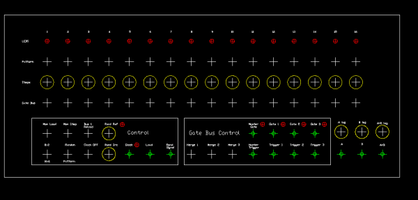
I whipped up a quick layout of the Model 2 in Autocad.
Not pretty, but for reference, it works.
Everything is spaced 25mm apart, this works nicely for 0,5 inch knobs on 16mm pots, and 4mm banana jacks, which I use.
There is slightly more than 25mm between the top four rows and the two control sections.
Looks like a model 2 fills a 5-unit rack panel the way I have it set up.
-White crosses are toggle switches
-Yellow circles are pots
-Green crosses with little green circles are in/out jacks
-Red circles/crosses are LED's
Hope it's useful to someone else... 
C
EDIT: Dang! Those letters are kinda small to read... 
| Description: |
| A quick and ugly panel-layout of the Super Klee Model 2... |
|
| Filesize: |
7.57 KB |
| Viewed: |
520 Time(s) |
| This image has been reduced to fit the page. Click on it to enlarge. |
|
|
|
|
Back to top
|
|
|
v-un-v
Janitor

Joined: May 16, 2005
Posts: 8932
Location: Birmingham, England, UK
Audio files: 11
G2 patch files: 1
|
| Posted: Sun Oct 01, 2006 12:50 pm Post subject:
|
|
|
| Coriolis wrote: |
I whipped up a quick layout of the Model 2 in Autocad.
Not pretty, but for reference, it works.
|
Has anyone looked at "Q-CAD"? It's very similar to AutoCAD LT and it also runs under Linux, Mac OSX, Windows, Solaris yet only costs £18! (UKP)
It's fab for designing front panels too
Failing that, UGS Solid Edge 2D (windows only) is just like fully blown Parametric AutoCAD 2007 yet is FREE!!
(I've been drowning in CAD packages for the last couple of weeks- ever since university started again- hence radio (internet) silence here too). All work and no play makes Tom a bad boy  
PS all we need now (to accompany the Klee is a CV to MIDI converter ! )
_________________
ACHTUNG!
ALLES TURISTEN UND NONTEKNISCHEN LOOKENPEEPERS!
DAS KOMPUTERMASCHINE IST NICHT FÜR DER GEFINGERPOKEN UND MITTENGRABEN! ODERWISE IST EASY TO SCHNAPPEN DER SPRINGENWERK, BLOWENFUSEN UND POPPENCORKEN MIT SPITZENSPARKSEN.
IST NICHT FÜR GEWERKEN BEI DUMMKOPFEN. DER RUBBERNECKEN SIGHTSEEREN KEEPEN DAS COTTONPICKEN HÄNDER IN DAS POCKETS MUSS.
ZO RELAXEN UND WATSCHEN DER BLINKENLICHTEN. |
|
|
Back to top
|
|
|
Coriolis
Joined: Apr 11, 2005
Posts: 616
Location: Stilling, Denmark
|
| Posted: Sun Oct 01, 2006 1:11 pm Post subject:
|
|
|
Those look nice!
I'm using Autodesk ABS for my schoolwork, but if I had to have something for hobby use, I'd rather eat than pay license fees for it, so it's good to see there are cheap alternatives!
C |
|
|
Back to top
|
|
|
v-un-v
Janitor
Joined: May 16, 2005
Posts: 8932
Location: Birmingham, England, UK
Audio files: 11
G2 patch files: 1
|
| Posted: Sun Oct 01, 2006 3:20 pm Post subject:
|
|
|
| Coriolis wrote: | if I had to have something for hobby use, I'd rather eat than pay license fees for it, so it's good to see there are cheap alternatives!
|
Exactly!
I'm on a war-path with by backward thinking university, and keep bombarding them with these suggestions. In fact I did the whole of the last semester on Q-Cad and still got a high grade
In this new semester I am yet again given no option and am being 'forced' to use the heavies (AutoCAD Architectual Desktop etc) again. I mean for christ's sake, it's a drawing right??
I'm now trying to opt out of one of my architectual modules to do a philosophy module instead
Think different!
_________________
ACHTUNG!
ALLES TURISTEN UND NONTEKNISCHEN LOOKENPEEPERS!
DAS KOMPUTERMASCHINE IST NICHT FÜR DER GEFINGERPOKEN UND MITTENGRABEN! ODERWISE IST EASY TO SCHNAPPEN DER SPRINGENWERK, BLOWENFUSEN UND POPPENCORKEN MIT SPITZENSPARKSEN.
IST NICHT FÜR GEWERKEN BEI DUMMKOPFEN. DER RUBBERNECKEN SIGHTSEEREN KEEPEN DAS COTTONPICKEN HÄNDER IN DAS POCKETS MUSS.
ZO RELAXEN UND WATSCHEN DER BLINKENLICHTEN. |
|
|
Back to top
|
|
|
Scott Stites
Janitor
Joined: Dec 23, 2005
Posts: 4127
Location: Mount Hope, KS USA
Audio files: 96
|
| Posted: Sun Oct 01, 2006 3:59 pm Post subject:
|
|
|
| Quote: | | Oh ... before I forget ... I really liked the idea about having a voltage controlled switch on the recirculation (etc.), I did that for my G2 patches and it can nicely break up the sequence and alter it every once in while under LFO control, and think PW modulation on that LFO |
I really like the idea as well - in fact, it was something I wanted to implement on the original Klee, but got sidetracked by all the other stuff. All of a sudden, right in front of my eyes, the parts are there - just nothing hooked up to them to do it.
On your G2 model, if possible, split the shift register up into two 8 stage sections so that you can switch between recirculating one 16 bit register or two 8 bit registers. Now, get a random smattering of bits in there. Circulate them 8X2 then circulate them 16X1, then go for 8X2 again - the past few days I've become used to redistributing the bits that way - one advantage over letting a few random bits in now and then is that you keep the same number of bits, but they just get rearranged. Depending on the timing, switching between 16X1 and 8X2 will always result in a different pattern each time you switch. When I think I need a few more bits, I flip to 8X2, let a few random bits enter the first register, then go through it all again. Either using this method or just using random input alone, one can come up with patterns that always seem to have a bit more going for them than just relying on the pattern switches themselves. The pattern switches are good for trying out different patterns, but they're also necessary as a sort of hardware memory should you get a pattern you want to save for later.
Coriolis - nice panel!! I like that a lot. But....I forgot to mention the range switch
Range switch is the jist of this included sample. It's a recording I just made using the 1V range. It consists of a 5 bit pattern. Pots are either full on or full off - I didn't go through any tedious tuning. Just cranked'em all the way one way or the other, shuffled the bits around and listened til a cool pattern emerged. This method really makes coming up with patterns very easy - if one want to fine tune it, one can still crank the pots for other intervals.
Same patch as above, 8X2 mode.
Cheers,
Scott |
|
|
Back to top
|
|
|
Uncle Krunkus
Moderator

Joined: Jul 11, 2005
Posts: 4761
Location: Sydney, Australia
Audio files: 52
G2 patch files: 1
|
| Posted: Sun Oct 01, 2006 4:42 pm Post subject:
|
|
|
I just had a look at the decoder schem, and realised that I still don't understand exactly what's going on!
Doesn't matter, I can still get it all on stripboard and work it out later.
I've decided to put the 4050 buffers on the decoder board. There's not much else on there, one side of every buffer goes to a stage controller (4066) anyway, so they are multiple board interconnections which would have to happen anyway. This way I can sort out the 4050 connections into neat little sequential lines. That makes it easy to connect with ribbon and 8 way headers. No one needs to worry about getting out of order. (except for me!) Why they couldn't put all the 4050 inputs down one side of the chip, outputs down the other, power back where it should be and an extra buffer across the NC pins, God alone knows! 
So the first board will be served up shortly! Just have to get the buffers off it and tidy up.
_________________
What makes a space ours, is what we put there, and what we do there. |
|
|
Back to top
|
|
|
Scott Stites
Janitor
Joined: Dec 23, 2005
Posts: 4127
Location: Mount Hope, KS USA
Audio files: 96
|
| Posted: Sun Oct 01, 2006 5:08 pm Post subject:
|
|
|
Those buffers are hideous. Agreed on the pinout - why in the world......
Can't wait to see the board. To be honest, I'll have to review where the saga left off - decoder, I believe. Time for another chapter. In short, the decoder has a step attenuator made up of the resistor/trimpot pairs for the different voltages. Notice the op amp with the 10/20K resistor divider - this buffers 10V, which each resistor/trimmer divides into the approprate voltage. Each of those voltages is sent to the input of a 4051.
A rotary switch sends +V to the diode matrix, which selects which voltage the 4051 will put out. That voltage is buffered and sent to each CD4066 section (4 CD4066's, 4 sections per CD4066, 16 sections total). A CD4066 section will pass that voltage when one of the the fat boys sends a bit to its control input. The output of each CD4066 section feeds one of the step pots. In this manner, the selected voltage range is presented to the top of the pot. Pots 1 through 8 feed 8 resistors which are summed together to be sent to the A voltage summer. Pots 9 through 16 feed 8 resistors which are summed together to be sent to the B voltage summer.
Forgot to mention in the last post, but matched resistors are pretty much a necessity on the mixer board and decoder, if one wants to have accurate ranges. Not that big of a deal - I just took a bag of 100K's and sorted them out with an Ohmmeter. The most of the same value I had was 99.8K, so I put those into the decoder, and the op amps that sum the voltages - BIG difference in tunability. I also put in offset trimmers to the first two op amps. The way it works, one op amp sums A, one op amp sums B, then the output of those two op amps go to the A+B mixer. Well, if those two have an offset, they'll add up in A+B, which will offset the output of A+B even more. Not a whole lot, a few millivolts each, but they do add up.
I should also mention that the range trimmers should be multi-turn pots. That makes it easy as fishin' to cal the voltages in.
Had a rough time posting that last post - dial up, PeoplePC, don't ask...but in the time it took to post it, while it was uploading the file for the third time, I went downstairs and tweaked another pattern that is just blowing me away. It's one of those that, no matter what key I hit on the keyboard, it just seems to fit.....sort of an arpeggiator that just won't let you hit the wrong key. I did it using the 1V range and setting one - just one!! - pot dead center and shaking up the pattern a bit then switching the gate bus around. Holy cow....
I'm not getting anything done.....again. Last thing to do is test that Gate Bus parts reduction. Must...get.....it.....done.
Cheerios,
Scott |
|
|
Back to top
|
|
|
Scott Stites
Janitor
Joined: Dec 23, 2005
Posts: 4127
Location: Mount Hope, KS USA
Audio files: 96
|
| Posted: Sun Oct 01, 2006 5:20 pm Post subject:
|
|
|
Hmmm....thought I should mention it - I've made no mention of it on the schematic, and it's not normal protocol to mark it as such, but you'll notice some of the ground symbols have a little 'A' next to them. This is 'analog ground'. IE, they should share their own trace/jumpers that go back to the source only at one point. Also, there is +VA and -VA, which have their own special little filter caps. Just insurance to keep any jitters out of our triocular exotic dancer.
Cheers again,
Scott |
|
|
Back to top
|
|
|
Scott Stites
Janitor
Joined: Dec 23, 2005
Posts: 4127
Location: Mount Hope, KS USA
Audio files: 96
|
| Posted: Sun Oct 01, 2006 7:24 pm Post subject:
|
|
|
The shiny bauble I mentioned a post or two ago....
1V range, 16X1 mode, all pots either hard left or hard right, except for one.....
Cheers,
Scott |
|
|
Back to top
|
|
|
Uncle Krunkus
Moderator
Joined: Jul 11, 2005
Posts: 4761
Location: Sydney, Australia
Audio files: 52
G2 patch files: 1
|
| Posted: Sun Oct 01, 2006 7:56 pm Post subject:
|
|
|
Yeah, that's cool, I'm hip to the whole "analogue ground" idea. I decided to incorporate it wherever appropriate from now on. My new power supply (when I get around to building it!) will have 4 way connectors to support DGround & AGround.
Multiturns on the range trimmers - check.
What do they reference from? - might not matter if they're all set at the same time?
_________________
What makes a space ours, is what we put there, and what we do there. |
|
|
Back to top
|
|
|
vtl5c3
Joined: Sep 08, 2006
Posts: 425
Location: PDX
Audio files: 13
|
| Posted: Sun Oct 01, 2006 8:07 pm Post subject:
distraction |
|
|
| not as raunchy as toadskin teddy, but I like it. Imagine if they had built a superklee into grampa's wurlitzer. |
|
|
Back to top
|
|
|
Scott Stites
Janitor
Joined: Dec 23, 2005
Posts: 4127
Location: Mount Hope, KS USA
Audio files: 96
|
| Posted: Sun Oct 01, 2006 9:31 pm Post subject:
|
|
|
| Quote: | | What do they reference from? - might not matter if they're all set at the same time? |
The trimpots are fed from a buffer that is fed 10V through a voltage divider (10K/20K). The voltage divider is fed from +VA (15V analog). If one wanted to get jiggy with it, a 10V reference IC or a zener could be used, but this certainly seems to be working just fine. The trimpots are not inter-reactive - IE, adjusting one doesn't change the setting of another - they're all fed from the same low impedance output of the buffer.
As far as raunch goes, here's a bit of raunch for Iris (our three eyed amphibian-based wardrobe shedding heroine): 16X1 using the 1/4 volt range, pots either full on or full off. This example uses the gate bus. Can't remember which merge switches I had going, but it starts out with two of the busses merged, which is the first rhythm heard, then one gate bus is un-merged, which adds an extra beat in there. Finally, the other gate bus is un-merged, which changes the rhythm again. I find the gate busses extremely useful for easily varying the rhythm without altering the sequence itself - the interaction of the gate bus with the Klee pattern is really the unsung half of the Klee - it's what really provides the balls to a lot of the Klees capabilities.
http://mypeoplepc.com/members/scottnoanh/sitebuildercontent/sitebuilderfiles/klee_gate_bus_fonk.mp3
1/4V Range, Pots either full on or full off, gate bus manipulation.
G'night,
Scott
Last edited by Scott Stites on Sat Nov 04, 2006 7:04 pm; edited 1 time in total |
|
|
Back to top
|
|
|
Uncle Krunkus
Moderator
Joined: Jul 11, 2005
Posts: 4761
Location: Sydney, Australia
Audio files: 52
G2 patch files: 1
|
| Posted: Mon Oct 02, 2006 5:52 am Post subject:
|
|
|
Just while I remember Scott,
I've swapped the comparators on the encoder schem.
I'm using pins 1, 2 and 3 (6&7 shorted, 5 to ground)
Almost done.
_________________
What makes a space ours, is what we put there, and what we do there. |
|
|
Back to top
|
|
|
Scott Stites
Janitor
Joined: Dec 23, 2005
Posts: 4127
Location: Mount Hope, KS USA
Audio files: 96
|
| Posted: Mon Oct 02, 2006 7:23 am Post subject:
|
|
|
Noted.
I didn't get through the whole Gate Bus reduced parts count experiment, but I ensured eliminating the first two inverters on each gate bus output (right before the NANDs) had no ill effects. One can Mickey Mouse a NAND leg as well as an Inverter (why does that sound vaguely obscene?).
I'm pretty sure I can get rid of those last two inverters on the Master Clock output as well. The one thing after that to check is to make sure the quad 324s will work fine instead of the dual 358s. I gotta find some breadboard space somewhere to try that out.
I'm wondering if a Zener on the voltage reference might not be a bad idea. I haven't had any problem referencing straight from the rail, but who knows what kind of power supply people will be using. I don't know if I have any of the value I'd want (9.1 to 10V) in any event, it wouldn't harm the stripboard a jot - the 20K would just be replaced by a zener. Shouldn't affect the resistor/trimmer values either.
Cheers,
Scott |
|
|
Back to top
|
|
|
Uncle Krunkus
Moderator
Joined: Jul 11, 2005
Posts: 4761
Location: Sydney, Australia
Audio files: 52
G2 patch files: 1
|
| Posted: Mon Oct 02, 2006 7:53 am Post subject:
|
|
|
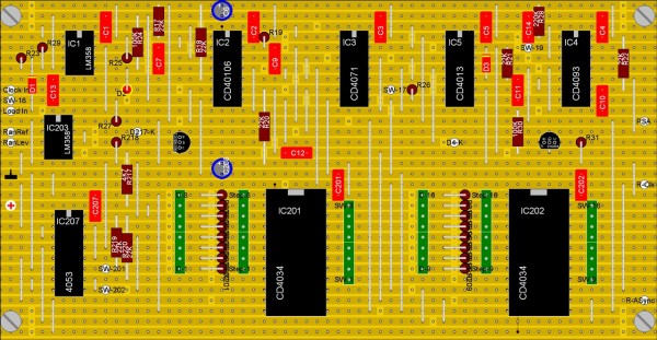
Super Klee Stripboard (Klee-B1)
All of the Clock & Load, and most of the Encoder.
Double checked, as yet unbuilt.
All the parts from the encoder schem have 200 added to their designator.
With no buffers, I've been able to make a little bit more room. There's space to use proper headers for the data lines, (if people want to).
There are 84 links all up.
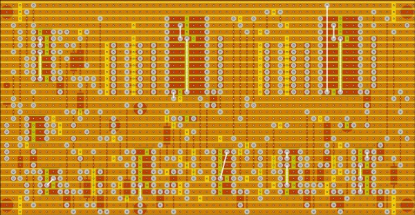
16 of which are under chips. I've shown them on the copperside pic (in white) for clarity but they should really go on the parts side before the IC sockets go in.
If there are any queries or problems, let me know. I'll edit this post to keep it the only accurate one for this board.
Edit (9-Oct-06) Updated layout.
| Description: |
|
| Filesize: |
254.5 KB |
| Viewed: |
376 Time(s) |
| This image has been reduced to fit the page. Click on it to enlarge. |
|
| Description: |
|
| Filesize: |
305.86 KB |
| Viewed: |
338 Time(s) |
| This image has been reduced to fit the page. Click on it to enlarge. |
|
_________________
What makes a space ours, is what we put there, and what we do there.
Last edited by Uncle Krunkus on Mon Oct 09, 2006 5:32 am; edited 1 time in total |
|
|
Back to top
|
|
|
Scott Stites
Janitor
Joined: Dec 23, 2005
Posts: 4127
Location: Mount Hope, KS USA
Audio files: 96
|
| Posted: Mon Oct 02, 2006 9:58 am Post subject:
|
|
|
Sweet!! Excellent work - quite amazing to get all of that on one stripboard. Nice apportionment of tasks - it makes more sense to put the CD4050s with the gate bus, since their main task is to drive the LEDs and provide the signals to the gate bus. Other than those blasted CD4050s, the gate bus will probably be rather stripboard friendly. Especially a reduced part version of it - gates aren't scattered out quite as haphazardly.
Not sure if the rest will fit on one board (doubtful) but it makes it obvious that the decoder and final mixer could share a board - it's the only section that uses +/-V and all that analog ground crap - it would make it easy to keep the grounds and power separated.
I didn't number the ref des's consecutively as a whole project, it made it easy to work out each section. I was going to go back and do something quite similar, so that'll work out - I'll do that with the schematics. Stay tuned for 'Showdown at the Decoder Corral', coming up next.....
Cheerios,
Scott |
|
|
Back to top
|
|
|
Scott Stites
Janitor
Joined: Dec 23, 2005
Posts: 4127
Location: Mount Hope, KS USA
Audio files: 96
|
| Posted: Mon Oct 02, 2006 10:42 am Post subject:
|
|
|
Episode 3: Showdown at the Decoder Corral
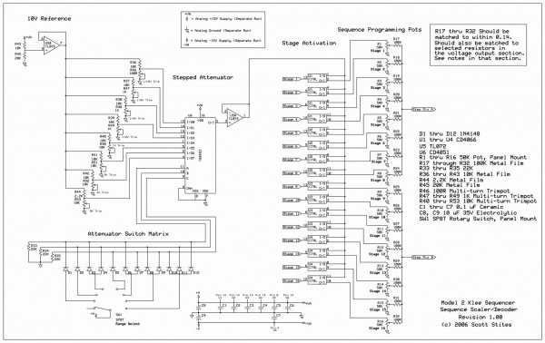
I've uploaded the current version of the Decoder schematic. Actually, it's the "Scaler/Decoder" because it also scales the maximum value each of the sequence pots is capable of providing.
Moving from left to right, we first see the 10V reference. R43 and R45 form a voltage divider that derives a 10V signal from the +15V rail. This 10V is fed to U5B, which is configured as a voltage buffer. The output of the buffer provides a low impedance 10V source that is fed to 8 sets of resistor/trimmer pairs. These resistor/trimmer pairs, SW1, and U6 form the stepped attenuator which is used to set the output range of the Klee sequence.
Each of these resistor/trimmer pairs is responsible for generating the range voltages, which are 1/12 V (0.0833V), 1/6V (0.166V), 1/4V (.025V), 1/2V (0.50V), 1V, 2V, 4V and 8V. Each of these voltages is fed to a pin of U6, a CD4051 1 of 8 multiplexer.
SW1, an 8 position rotary switch, R33 through R35, and D1 through D12 provide the means to control which of these range voltages becomes present on pin 3 of the CD4051. D1 through D12 form a diode matrix switch which converts the positive voltage selected by SW1 to a 3 bit binary address, which is used to determine which of the input pins of the CD4051 is connected to the output pin, pin 3. R33 through R35 serve as pull-down resistors so that when an address pin does not have a positive voltage on it, it will be reliably pulled to 0V.
The output of U6 is buffered by U5A and sent to the 'stage activation' section of the decoder board. This voltage is applied to the input of 16 total CD4066 sections, each of which acts as an On/Off switch. The control input of each CD4066 section is connected individually to one of the output pins of the CD4034 'fat boy' shift register ICs in the encoder section. These are what the labels "Stage N" ('Stage 1', 'Stage 2', etc) signify.
The output of each CD4066 section is connected to the top of a sequence programming pot. These are the pots on the front panel of the Klee that the operator uses to program the sequence voltages.
When the control input of a CD4066 is brought high by one of the shift register ICs, it passes the voltage applied to it from the stepped attenuator section to the top of its dedicated control pot. The pot then forms a voltage divider, variable by the operator, to set the output voltage for that particular stage. When the CD4066 control input is low, the output of the pot wiper will be 0V.
Each of the pots feeds a 100K resistor. You'll notice that the 16 resistors are grouped into two sets of eight resistors. The first group of eight resistors are combined to put out Step Mix A and the second group of eight resistors are combined to put out Step Mix B. This allows the Klee to operate in either 8X2 or 16X1 modes. Step Mix A and Step Mix B each go to the as yet unseen voltage mixer section of the Klee, the final piece of the puzzle. The 16 resistors forming Step Mix A and Step Mix B must be matched to within 0.1% - this allows a fairly precise mix of voltages to reach the voltage mixers when each pot is cranked wide open. This allows that all pots cranked wide open will supply an accurate mix of the voltage provided by the stepped attenuator.
Matching the resistors is a piece of cake. I just took a bag of them, measured them on my DMM, and sorted them out in piles according to what they read on the DMM. I had more 100K resistors with a value of 99.8K than I had of any other, so that's what I used for the breadboard. When measuring them, I made sure they read *solidly* 99.8K - if it looked like the DMM wanted to flicker down to 99.7K or up to 99.9K, I rejected those resistors from the pool. Make sure you have around 25 of them that match up exactly (you'll need a few more down the road in the voltage mixing section).
I used 50K pots for the programming pots - this allows the pot to not be loaded down by the output resistor, and allows for a smoother range of adjustment in the pot.
Notice the voltages have an 'A' by them, and the ground also has an 'A' - this signifies that these paths must go back to the source directly, and not be mixed with all that nasty digital crap that's going on elsewhere in the Klee.
And that's it, in all it's anticlimatic glory......
Cheerio,
Scott
Edit: Schematic has been revised since this post. Zip file with the latest revision is downstream in this thread. Check first post of thread to find exact whereabouts.
| Description: |
|
| Filesize: |
252.67 KB |
| Viewed: |
702 Time(s) |
| This image has been reduced to fit the page. Click on it to enlarge. |
|
Last edited by Scott Stites on Sun Oct 08, 2006 4:58 pm; edited 3 times in total |
|
|
Back to top
|
|
|
v-un-v
Janitor
Joined: May 16, 2005
Posts: 8932
Location: Birmingham, England, UK
Audio files: 11
G2 patch files: 1
|
| Posted: Mon Oct 02, 2006 1:46 pm Post subject:
|
|
|
These mp3's are beautiful!
So is the stripboard
Thank you so much
_________________
ACHTUNG!
ALLES TURISTEN UND NONTEKNISCHEN LOOKENPEEPERS!
DAS KOMPUTERMASCHINE IST NICHT FÜR DER GEFINGERPOKEN UND MITTENGRABEN! ODERWISE IST EASY TO SCHNAPPEN DER SPRINGENWERK, BLOWENFUSEN UND POPPENCORKEN MIT SPITZENSPARKSEN.
IST NICHT FÜR GEWERKEN BEI DUMMKOPFEN. DER RUBBERNECKEN SIGHTSEEREN KEEPEN DAS COTTONPICKEN HÄNDER IN DAS POCKETS MUSS.
ZO RELAXEN UND WATSCHEN DER BLINKENLICHTEN. |
|
|
Back to top
|
|
|
Scott Stites
Janitor
Joined: Dec 23, 2005
Posts: 4127
Location: Mount Hope, KS USA
Audio files: 96
|
| Posted: Mon Oct 02, 2006 2:45 pm Post subject:
|
|
|
Yes, a mighty thank you to Uncle K for going where no stripboarder has gone before.....
Cheers,
Scott |
|
|
Back to top
|
|
|
Uncle Krunkus
Moderator
Joined: Jul 11, 2005
Posts: 4761
Location: Sydney, Australia
Audio files: 52
G2 patch files: 1
|
| Posted: Mon Oct 02, 2006 5:06 pm Post subject:
|
|
|
Hey Scott,
you probably already explained this, but why the 4051? Why not just switch 1 of 8 trimmers through to the buffer? Is it the wire runs up to the front panel and back? Yeah, that's probably it. Thanks for the quick reply!
As for the layout, thanks. I think it looks pretty good too! The question is, does it work? Who's gonna test them out? Hey, that can be your job Tom! I'm sure you can take a month off from your studies to build a Super Klee can't you?
_________________
What makes a space ours, is what we put there, and what we do there. |
|
|
Back to top
|
|
|
Scott Stites
Janitor
Joined: Dec 23, 2005
Posts: 4127
Location: Mount Hope, KS USA
Audio files: 96
|
| Posted: Mon Oct 02, 2006 7:51 pm Post subject:
|
|
|
| Quote: | | Is it the wire runs up to the front panel and back? Yeah, that's probably it. |
Yep, that's mostly it. In this case, it's not any easier to wire, but I wasn't all that hep on running .083V to a rotary and back. Using the CD4051 makes things a bit easier to predict, and one doesn't have to worry about oxidation of contacts and so forth affecting the voltage over time. This way, the voltages make a short little hop over to the 4051, through the buffer, and on their merry way.
A second, more nefarious reason is that it leaves open the possibility of ostensibly saving panel space by replacing the rotary with a smaller momentary switch, and using a CD4017 or something like that to step through the ranges. Of course, in that case, one would still need an indication of range, which would involve LEDs, and likely end up not saving any space at all. A momentary, however, on a future model, would allow the full original Krunkus range and then some (16 voltages) if one used a CD4067 instead of a CD4051. CD4067 is another fat boy, BTW, a hormonal 4051 with CD4034 proportions. In this case, though, one would have 16 selections without resorting to a 16 position switch.
| Quote: | | Hey, that can be your job Tom! I'm sure you can take a month off from your studies to build a Super Klee can't you? |
It's settled then, Tom is our official guinea pig. Of course, once his significant other kicks him out about 4 days into it, we'll all have to take up a collection to help him with his new digs.....
BTW, Uncle K, *don't* follow that decreased parts count Gate Bus schematic I posted earlier - the one that says "Untested" on it. Master trigger will not be very triggery - I went and left off the inverter to allow it to be the right polarity. It's still doable - I just use that spare one up at the top of the schematic. I tried it out tonight, and it works. In fact, that sews up all the gates - not a wasted IC section in sight on that schematic. Thomas Henry would be proud. He'd also figure out how to do it with a rubber band and a drinking straw if given enough time. Still haven't tested the 324s there, but I'm thinking they'll do fine. But they still must be tested. There are few things as unpleasant as finding an assumption was wrong after soldering everything up.
Oh, yes, I eliminated 8 superfluous resistors as well - they were vestigial from a previous approach to it, and I never removed them.
Cheerios,
Scott |
|
|
Back to top
|
|
|
|

 Forum index » DIY Hardware and Software » Klee sequencer

