| Author |
Message |
THeff

Joined: Sep 01, 2006
Posts: 229
Location: Florida
Audio files: 33
|
 Posted: Wed May 08, 2013 10:16 am Post subject: Posted: Wed May 08, 2013 10:16 am Post subject:
|
  |
|
xpmtl,
Try grounding the 68k resistor going to the CV input on your schematic to see if it fixes the pitch control problem. In the original schematic this is R106 and goes to the pitch pedal jack. With nothing plugged in it is normally grounded. This forms a voltage divider to get the pitch voltage in the right range.
I would suggest getting everything to work on your existing PCB before spinning a new one. Use it as the prototype to work out all the bugs so they don't carry over to the new design...just a suggestion.
-Tim |
|
|
Back to top
|
|
 |
xnor

Joined: Apr 24, 2013
Posts: 5
Location: Cascadia
|
|
|
Back to top
|
|
|
jmejia
Joined: Mar 12, 2009
Posts: 114
Location: portland
|
| Posted: Wed May 08, 2013 11:56 am Post subject:
|
|
|
| Tim - any chance you could post an audio file of your working circuit? Both for reference and inspiration! |
|
|
Back to top
|
|
|
xpmtl

Joined: Aug 10, 2007
Posts: 162
Location: Brussels, Belgium
|
| Posted: Wed May 08, 2013 1:18 pm Post subject:
|
|
|
Thanks Tim
There's another resistor missing in Fonik schematic, R105 (33K).
So i've grounded the pitch input and with R105 installed i got the pitch pot kinda working. It does sweep but only in the negative domain (between -15V and 3V). (Without R105 it doesn't work)
I've also disabled the LFO but then i don't hear anything, the filter still doesn't oscillate.
Today I've redrawn the original schematic with the good references values. Tomorrow it's a bank holliday here so i'll have time to re-check everything and maybe layout the new board.
The current board is a real mess, lifted traces and whatnot, that's why i wanted to start fresh again, I may have introduced more errors than there were already.
_________________
http://sdiy.xpmtl.net |
|
|
Back to top
|
|
|
jmejia
Joined: Mar 12, 2009
Posts: 114
Location: portland
|
| Posted: Wed May 08, 2013 2:15 pm Post subject:
|
|
|
Yeah - I think there is definitely an issue with our pitch/cv input section.. but I'm not totally sure what it SHOULD look like yet.
Tim, did you end up drawing a schematic for your single voice? Or maybe you have some edits to that section you could share? |
|
|
Back to top
|
|
|
THeff
Joined: Sep 01, 2006
Posts: 229
Location: Florida
Audio files: 33
|
| Posted: Wed May 08, 2013 7:00 pm Post subject:
|
|
|
xpmtl & jmejia,
Let me answer the questions and give some more feedback to your responses.
1.) I did not draw a new schematic I just followed the original and built it section by section.
2.) The schematic only shows the overall pitch control which I wired as an individual control for the one channel that I made.
3.) When you say you can't hear the oscillator are you saying at the output (emitter T6) or pin 1 of IC3a? If you see it at pin 1 of IC3a and not the output then it is a problem in the VCA (CA3080) section.
4.) Is the filter working as a filter? The Tone/Noise control (S4) is the Resonance control on the filter and it will only oscillate when it is close to the Tone side of the pot. At the Noise side of the pot it is only a filter for the noise. Can you hear the noise on pin 1 of IC3a that sounds filtered as you move the pitch control?
5.) Make sure you are not loading down the output of IC3a with your monitor amplifier. I would connect a 10k resistor to pin 1 of IC3a and then connect your amplifier/speakers to that (just for testing).
6.) You said you saw a sine wave on pin 1 of IC3a that was 2V p/p. I would think that has to be coming from the filter/oscillator, not the LFO, because the LFO only puts out a triangle wave and a square wave.
7.) The base of transistor T2 is the summing point for all of the pitch control voltages, Impact, Bend, LFO, Run Gen, and Pitch control. If any of those summing resistors is not connected correctly it could put the filter into a range where it will not oscillate properly. The Bend Up/Down switch is not center off so make sure the 68k resistor (R28) is connected one way or the other (if you have not installed a switch yet).
8.) I will try to record some audio samples in the next day or so.
-Tim |
|
|
Back to top
|
|
|
xpmtl
Joined: Aug 10, 2007
Posts: 162
Location: Brussels, Belgium
|
| Posted: Sat May 11, 2013 8:01 am Post subject:
|
|
|
Hi folks,
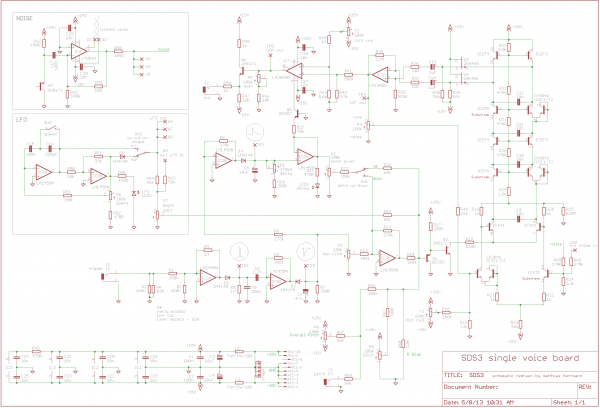
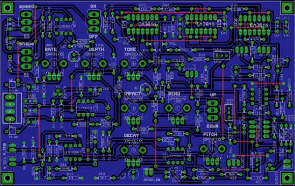
Right, today I've made a new board based on the original schematic with Tim's corrections. Haven't tested it thoroughly yet but it works. At least better than the old one 
The good news is that it oscillates (at last) and that all the functions work.
There are some things that are a bit odd but I think it needs to be calibrated. I just finished building it so i'll see that tomorrow.
So far the major problem is noise and the pitch is too high even at the lowest setting.
Regarding noise, as you can see in the schematic, there's three resistors in series. 100K, 270K and 100K (from the bleed circuit). that's obviously too much there but it's how it's drawn on the original schematic. I've quickly tested bypassing the 2 latter resistors and using only 100K but it's still to much apparently. Noise level is very faint. If i bypass all of them then the noise is horrible and way too high. I'll test other values tomorrow...
Regarding Pitch, i can't get bass sounds, it's all high pitched ones, so i guess there's something to look into there too.
There is a resistor that needs to be left out of my schematic : R19 (56K). I thought it was needed but apparently not. I can't get my head around how the dpdt switch works...
More news tomorrow after I spend some time with the thing.
| Description: |
|
| Filesize: |
83.76 KB |
| Viewed: |
892 Time(s) |
| This image has been reduced to fit the page. Click on it to enlarge. |
|
| Description: |
|
| Filesize: |
101.79 KB |
| Viewed: |
1560 Time(s) |
| This image has been reduced to fit the page. Click on it to enlarge. |
|
_________________
http://sdiy.xpmtl.net
Last edited by xpmtl on Sat May 18, 2013 1:26 pm; edited 3 times in total |
|
|
Back to top
|
|
|
xpmtl
Joined: Aug 10, 2007
Posts: 162
Location: Brussels, Belgium
|
| Posted: Mon May 13, 2013 1:42 am Post subject:
|
|
|
Hi all,
Fiddled with it a bit more yesterday. Some observations :
- Pitch pot works but only from -3.5V to 2V. Bellow and above the filter doesn't oscillate. I tried adding Jmejia individual pitch pot, but result is the same.
- The range on the decay pot is also a bit funny. At 0 i get short decay but at 0.5 the decay is already too long.. Now that i'm writing that I think I wired it backwards, that would explain the behavior...
- Noise pot at 100% noise side makes the filter silent.
That's it for now. I still need to check the voltages on the 3086.
Now that we get the same base I don't get why this doesn't work as Tim's.
Maybe it is the transistors I used? Couldn't get the npn and the fet so i used equivalents. According to my seller's book BC547 and BF245 were what was advised as replacements.
_________________
http://sdiy.xpmtl.net |
|
|
Back to top
|
|
|
THeff
Joined: Sep 01, 2006
Posts: 229
Location: Florida
Audio files: 33
|
| Posted: Mon May 13, 2013 6:33 pm Post subject:
|
|
|
| Nice PCB! |
|
|
Back to top
|
|
|
jmejia
Joined: Mar 12, 2009
Posts: 114
Location: portland
|
| Posted: Tue May 14, 2013 2:15 pm Post subject:
|
|
|
Hmm.. yeah that's very similar to the problems we're having with our proto. Damn.
There must be some corrections still needed on the factory schemo.
Hopefully we're getting close! |
|
|
Back to top
|
|
|
THeff
Joined: Sep 01, 2006
Posts: 229
Location: Florida
Audio files: 33
|
| Posted: Tue May 14, 2013 5:03 pm Post subject:
|
|
|
xpmtl,
I have been out of town for a few days so I haven't had much time to look at your schematic. After looking at the latest schematic I notice two things that will affect the pitch. First, 56k resistor R19 is only used with the run generator which you are not using. This should be removed and not connected to the Impact pot R15.
If did want to implement the run generator the cathode of diode D5 connects to the Impact pot and the anodes goes to the junction of R79 and R80 (run trigger). Resistor R19 would connect to the staircase waveform of the run generator (R89 via the on/off switch).
Second, as I mentioned earlier the junction of R105 and R106 (you labeled it Pitch_CV) should be grounded under normal operation. The original schematic shows this point going to the Pitch Pedal jack which is grounded unless you plug in the pedal. I believe the pedal used here is just pot which provides a variable resistance to ground. I don't believe it provides a source of voltage. If you don't ground this point it will raise your pitch because of the voltage supplied by R105.
I don't think you really want to make the Pitch Pedal your CV input. If you want a CV input you probably want to connect another 100k resistor to the base of T2 and input your CV there.
I have one other change to report on the original schematic. After doing more testing and getting ready to record some samples to post I noticed distortion of the output from transistor T6. I found out that IC8 CA3080 was being overdriven and clipping the sinewave. Resistor R65 (3.3k) and resistor R64 (5.6k) both need to be changed to 1k. With this change I get a clean sinewave on the output. This change will not help with your pitch issue only the overall performance once you get everything working.
-Tim |
|
|
Back to top
|
|
|
THeff
Joined: Sep 01, 2006
Posts: 229
Location: Florida
Audio files: 33
|
|
|
Back to top
|
|
|
xpmtl
Joined: Aug 10, 2007
Posts: 162
Location: Brussels, Belgium
|
| Posted: Tue May 14, 2013 11:07 pm Post subject:
|
|
|
Hi Tim,
Thanks for the sound samples, it's quite informative on the way this should sound.
I should have be more clear about it in my latest post but I didn't install R19 and i've grounded the Pitch CV input following your earlier recommendation.
I noticed that the sinewave was clipping also, i'll change the resistors to 1K tonight.
Regarding the pitch issue, i'm a bit lost to be honest, my knowledge stops at building pcbs i'm afraid
I suspect one of the functions sends too much juice to the T2 tranny, I'll try to disconnect each one in sequence leaving only the pitch pot at first then adding them to see which one is messing stuff up.
_________________
http://sdiy.xpmtl.net |
|
|
Back to top
|
|
|
arnoid

Joined: Aug 23, 2009
Posts: 57
Location: Belgium
|
| Posted: Wed May 15, 2013 5:17 am Post subject:
|
|
|
| THeff wrote: | Here is an audio sample of the DIY SDS-3 drum. It is triggered by a rhythm generator pulse so there is no amplitude variation like you will get if you trigger it with true piezo drum sensor.
I have put it in all of the modes except the run generator.
Plain oscillator
Impact click added
Bend Down & Up
Delay short and long
LFO Triangle & Square, fast & slow
Noise various pitch and resonance settings.
LFO High range acting as a ring modulator.
-Tim |
Sounds nice ! There certainly are some cool drumsounds in that demo
How sounds the run generator ? 
_________________
http://www.soundcloud.com/arnoid
http://www.facebook.com/arnoid
Last edited by arnoid on Thu May 16, 2013 2:11 am; edited 1 time in total |
|
|
Back to top
|
|
|
THeff
Joined: Sep 01, 2006
Posts: 229
Location: Florida
Audio files: 33
|
| Posted: Wed May 15, 2013 7:38 pm Post subject:
|
|
|
xpmtl,
I looked over your schematic pretty closely again and I don't see any errors. I will mention that I did use all of the original transistors that were specified.
One thing you may want to try, just for a sanity check is to disconnect all of the resistors connected to the base of T2 except the 3.3k to ground. Then connect a 100k resistor to the base of T2 and the other end to a 10k - 50k pot. Connect +15V to one end of the pot and -15 to the other end.
Set the Tone/Noise control fully to the tone position.
Sweep the range of the pot while monitoring pin 1 of IC3a and you should be able to swing the full range of the oscillator. Mine will swing from about 33Hz to 25KHz just by sweeping the Pitch control from end to end.
If you can get this kind of range then you can probably assume that your oscillator is fine.
I would then connect only R33 again and this will make the Pitch work and you can see what kind of range you get with just that connected.
If that gives you good range then there is something wrong with one of the circuits that gets summed to the base of T2 (LFO, Impact, or Bend).
-Tim |
|
|
Back to top
|
|
|
xpmtl
Joined: Aug 10, 2007
Posts: 162
Location: Brussels, Belgium
|
| Posted: Wed May 15, 2013 10:18 pm Post subject:
|
|
|
Hi Tim,
Life got in the way yesterday so I didn't have time to fiddle with it. Hopefully i'll do that tonight.
I need to order the right transistors i think, I checked the datasheets and there's quite a significant difference between the one I used and the originals. Don't know if that could affect the pitch problem but it's worth trying too.
Anyways i'll try your solution first and we'll see from there.
Thanks
_________________
http://sdiy.xpmtl.net |
|
|
Back to top
|
|
|
xpmtl
Joined: Aug 10, 2007
Posts: 162
Location: Brussels, Belgium
|
| Posted: Wed May 15, 2013 11:35 pm Post subject:
|
|
|
Couldn't go to work before testing it
So, i disconnected R23, R28, R33. LFO switch in Off position. Tone pot on Tone position. That leaves only the 3K3 resistor.
Then i connected a 10k pot with a 100K resistor to the center pin of T2 with +/- 15V on the pot outer lugs.
Results are about the same as before. The filter sweeps only on a very limited range. I also noticed it's not a very nice sweep, its kinda start abruptly, higher than a normal VCF sweep.
I measured the center pin on T2 : -0.45V to 0.45V from one end of the pot to the other.
I get a waveform on Pin 1 of IC3 from -1.2V to 1.1 V on the center pin of the pot. Out of that range it's silent except after 1.1V where i get hiss.
So something is not working properly on the Filter section.
I'll check the voltages on the 3086s tonight when i get back home.
While I was at it, I wired the Decay pot correctly, now this work...
I also ordered the correct transistors from eBay (can't find them locally), should get them quickly I hope.
More later
_________________
http://sdiy.xpmtl.net |
|
|
Back to top
|
|
|
THeff
Joined: Sep 01, 2006
Posts: 229
Location: Florida
Audio files: 33
|
| Posted: Thu May 16, 2013 10:12 am Post subject:
|
|
|
Xpmtl,
I'm at work right now so I can't make any measurements but I would look closely at T2 and T3. Double check the pinout of the trans you used and make sure they are inserted correctly. If you are getting a sinewave at pin 1 of IC3a then I think 99% of the filter is correct. It seems like you only have a control problem which be related to T2 & T3.
-Tim |
|
|
Back to top
|
|
|
xpmtl
Joined: Aug 10, 2007
Posts: 162
Location: Brussels, Belgium
|
| Posted: Sat May 18, 2013 3:52 am Post subject:
|
|
|
Houston, we have a lift off....
... and the culprit were... the FETs.
So I fiddle with it for 3 hours this morning, First I checked T2, T3 but these were inserted correctly, then i changed the BC547 to a 2N3392 i had around and who is a perfect replacement for 2N5172. Still no dice. Then out of curiosity i tried a 2N5485 for the FETs but still no go. Finally and i don't know why, I swapped the BF245 for two other BF245 from a different batch and it worked!
Either the ones I installed initially were DOA (i bought them last week) or some magic happened
I'll try replacing all the trannies with the original ones once they arrive (probably during next week).
So now everything works but i still have to fiddle with the noise circuit. Not only it doesn't sound very good but the balance between Tone and Noise is not great. There is another problem, when the pot is all the way to the noise position, noise disappears and obviously tone too.
Apart from that it's all good.
Once i receive the trannies i'll test the circuit with them and update the schematics.
Again I want to thank you Tim for the great job you did resurrecting the thing and helping out so much for debugging.
_________________
http://sdiy.xpmtl.net
Last edited by xpmtl on Sat May 18, 2013 7:20 am; edited 1 time in total |
|
|
Back to top
|
|
|
xpmtl
Joined: Aug 10, 2007
Posts: 162
Location: Brussels, Belgium
|
| Posted: Sat May 18, 2013 4:30 am Post subject:
|
|
|
I fixed the noise circuit...
That's very odd but i think that the pinout of the BC547 in the Eagle Library is reversed.
I simply turned the transistor around and now it works.
That would also partly explain why the pitch was not working properly as i replaced T3 with the 2N3392.
I also tried different values for the twisted wires : 1pF, 1.5pf, 1.8pF and 2pF.
But i find that without any capacitor it sounds even better.
_________________
http://sdiy.xpmtl.net |
|
|
Back to top
|
|
|
Luka

Joined: Jun 29, 2007
Posts: 1003
Location: Melb.
|
|
|
Back to top
|
|
|
THeff
Joined: Sep 01, 2006
Posts: 229
Location: Florida
Audio files: 33
|
|
|
Back to top
|
|
|
xpmtl
Joined: Aug 10, 2007
Posts: 162
Location: Brussels, Belgium
|
| Posted: Sat May 18, 2013 7:12 am Post subject:
|
|
|
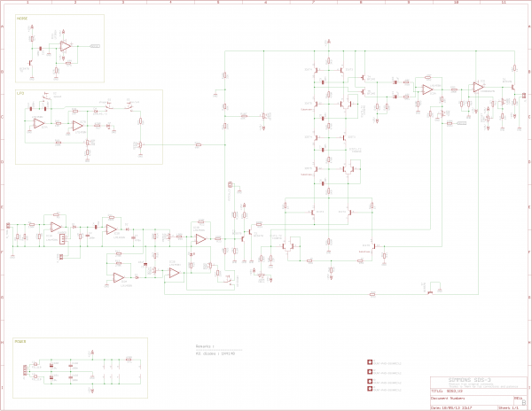
Updated Schematic on page 11 and deleted the old one.
Nice demo Tim. I'm curious to hear the Run Generator in action.
x.
_________________
http://sdiy.xpmtl.net |
|
|
Back to top
|
|
|
THeff
Joined: Sep 01, 2006
Posts: 229
Location: Florida
Audio files: 33
|
| Posted: Sat May 18, 2013 8:18 am Post subject:
|
|
|
Hey xpmtl,
Don't forget to change resistors R64 & R65 to 1k. Also, I came to the same conclusion you did about the noise circuit and removed the 1-2 pF capacitor altogether. I couldn't get a crisp sound with it installed.
At some point I think I am going to separate the noise/tone control. I think I will make the existing control just a resonance control like the ARP 4035 and put a separate pot in to adjust the noise level from 0 - 100%.
I will do a run generator demo at some point, but it's not that exciting in my opinion.
-Tim |
|
|
Back to top
|
|
|
xpmtl
Joined: Aug 10, 2007
Posts: 162
Location: Brussels, Belgium
|
| Posted: Sat May 18, 2013 1:05 pm Post subject:
|
|
|
Oops, completely forgot about those two. I've updated the schematic.
Thanks for the reminder.
x.
_________________
http://sdiy.xpmtl.net |
|
|
Back to top
|
|
|
|

 Forum index » DIY Hardware and Software