| Author |
Message |
diablojoy

Joined: Sep 07, 2008
Posts: 809
Location: melbourne australia
Audio files: 11
|
 Posted: Sat Jan 14, 2012 10:29 pm Post subject: Posted: Sat Jan 14, 2012 10:29 pm Post subject:
|
  |
|
just layed out and built a very rough pnp board today
will see how it goes in testing
may redo it later for euro size
just a little too wide at the moment
haha first test fail put a socket in backward and consequently
also the tl074 , cracked the bastard in half 
_________________
In an infinite universe one might very well
ask where the hell am I
oh yeah thats right the land of OZ
as good an answer as any |
|
|
Back to top
|
|
 |
diablojoy
Joined: Sep 07, 2008
Posts: 809
Location: melbourne australia
Audio files: 11
|
| Posted: Sun Jan 15, 2012 12:32 am Post subject:
|
|
|
ok working sort of
definitely getting waves blending on both outputs [audio rate]
and they look opposite ok but
i think i have an error in my layout perhaps
cant get any adjustment out of the trim at either end its like its not even there.
+5.9v to -5.9v shows the same at both of the outputs depending on where the pot is
the CV pot does have an effect on the output at least , an LFO into it
is interesting
supply is +15/-15 so tried 301K for the 220k maybe higher needed?
also didnt have 47K for the trimmer so used a 100k multiturn instead
_________________
In an infinite universe one might very well
ask where the hell am I
oh yeah thats right the land of OZ
as good an answer as any |
|
|
Back to top
|
|
|
diablojoy
Joined: Sep 07, 2008
Posts: 809
Location: melbourne australia
Audio files: 11
|
| Posted: Sun Jan 15, 2012 2:58 am Post subject:
|
|
|
sorted it ,missed a trace 
working good now
the trimmer adjustment went well
301K seems good for 15 volt supplies
no time left tonight will try to post something tomorrow
_________________
In an infinite universe one might very well
ask where the hell am I
oh yeah thats right the land of OZ
as good an answer as any |
|
|
Back to top
|
|
|
PHOBoS

Joined: Jan 14, 2010
Posts: 5947
Location: Moon Base
Audio files: 709
|
|
|
Back to top
|
|
|
asterisk
Joined: Sep 17, 2011
Posts: 17
Location: burlington, VT
|
| Posted: Sun Jan 15, 2012 11:38 am Post subject:
|
|
|
| this would be a good circuit to make a PCB for. |
|
|
Back to top
|
|
|
diablojoy
Joined: Sep 07, 2008
Posts: 809
Location: melbourne australia
Audio files: 11
|
| Posted: Sun Jan 15, 2012 4:19 pm Post subject:
|
|
|
interesting outputs if a higher freq is used into the cv input compared to the normal inputs
nice perfboard layout of yours by the way
the board i drew up has 3 board mounted pots [ i added attenuators on both the normal inputs ] for more variation
so i can try out the bigger cv than input wave form idea
wasnt concentrating on that last night and ran out of time
was thinking an attenuvertor on the cv input might be good
to try out as well
I have to do the layout again anyway need to get it under 44mm wide
dual layer would make it easy to lay out but harder for self etching
A triple or quad panel of these would be good and well worth having
i think
would you consider doing a board run of your final design in the future?
if enough interest develops of course.
_________________
In an infinite universe one might very well
ask where the hell am I
oh yeah thats right the land of OZ
as good an answer as any |
|
|
Back to top
|
|
|
emdot_ambient
Joined: Nov 22, 2009
Posts: 667
Location: Frederick, MD
|
|
|
Back to top
|
|
|
PHOBoS
Joined: Jan 14, 2010
Posts: 5947
Location: Moon Base
Audio files: 709
|
| Posted: Mon Jan 16, 2012 1:38 pm Post subject:
|
|
|
| diablojoy wrote: | the board i drew up has 3 board mounted pots [I added attenuators
on both the normal inputs ] for more variation so i can try out the bigger cv than
input wave form idea. wasnt concentrating on that last night and ran out of time
was thinking an attenuator on the cv input might be good to try out as well. |
I tought about adding some pots, but the synth I'm using it for is
allready getting out of hand (I'll probably have to change my initial idea
for it) so didn't want to add even more pots. But it's definitely a usefull
addition. 
| Quote: | I have to do the layout again anyway need to get it under 44mm wide
dual layer would make it easy to lay out but harder for self etching A triple
or quad panel of these would be good and well worth having i think would you
consider doing a board run of your final design in thefuture? if enough
interest develops of course. |
yes, I am considering it. I never had any PCB's manufactured before but
I think I found a good place to let them made and if my calculations are
correct then a standard PCB (single layer, solder mask, silk screen) of
my design would be around €5,- (and that's for an order of 10 pieces it
get's cheaper for more). Not sure if you mean my board or your new layout btw.
But I might order a couple of my design, even if there is no interest, just for myself.
There a few things I might want to change though. I'm gonna make the
soldering pads a bit larger, and maybe make the traces bigger or/and
add a ground plane. The power input is usefull for me, but I could probably
add an option for different connectors, same thing goes for the jacks.
And the trimpot will have some extra pads to use a multitrim.
I could make a completely new layout because if it's not for perfboard I
don't have to use a 0.1" grid and I might get it a bit smaller. On the other
hand, this design is allready tested, very easy to self etch (and possible to
build on perf) and because I want to have the connectors on the board I
probably won't get it very much smaller anyway. Of course you're free to install the
connectors or use wires, that's why I allready added some extra mounting holes (which
are useless with the jacks installed) and the dotted line in case you want to make
it a bit smaller.
So I'll probably just improve my design a bit and see of I can get a testrun of boards
made. And if there's any interest I can get more made or just make the files
available and let someone else do it since I don't have any experience with this. 
edit, because of the spacing between the components of my current design I could also
add part numbers next to it.
_________________
"My perf, it's full of holes!"
http://phobos.000space.com/
SoundCloud BandCamp MixCloud Stickney Synthyards Captain Collider Twitch YouTube
Last edited by PHOBoS on Mon Jan 16, 2012 2:22 pm; edited 1 time in total |
|
|
Back to top
|
|
|
asterisk
Joined: Sep 17, 2011
Posts: 17
Location: burlington, VT
|
| Posted: Mon Jan 16, 2012 2:03 pm Post subject:
|
|
|
| if you get some boards made, count me in for one. |
|
|
Back to top
|
|
|
diablojoy
Joined: Sep 07, 2008
Posts: 809
Location: melbourne australia
Audio files: 11
|
| Posted: Mon Jan 16, 2012 5:21 pm Post subject:
|
|
|
it's your design so i figure its up to you
I thought only to do a layout for myself primarily as well
but would happily send you the files if you wanted them , doing a quick layout is not much work for me and gives me a distraction while waiting for my sympleseq parts to come in . if what i do can be shared all the better. this is purely a hobby for me
my thoughts with regards to board design were to bring the board dimensions under 44mm in width for people who work in RU dimensions
with board mounted pots to make building simple and easy.
even better if the jacks were also board mounted
if it can be panelled in a euro format than a lot more people might be interested my 2 cents worth anyway
| Quote: | | And the trimpot will have some extra pads to use a multitrim. |
a very good idea i used a side adjust 15 turn and its still a bit touchy.
also may try lowering that 301K after looking at it again last night i dont quite get the full adjustment if the inputs are not attenuated .
perhaps a gain of 0.5 ... 240K for 15v supply
_________________
In an infinite universe one might very well
ask where the hell am I
oh yeah thats right the land of OZ
as good an answer as any |
|
|
Back to top
|
|
|
PHOBoS
Joined: Jan 14, 2010
Posts: 5947
Location: Moon Base
Audio files: 709
|
| Posted: Tue Jan 17, 2012 7:34 am Post subject:
|
|
|
| Quote: | it's your design so i figure its up to you
I thought only to do a layout for myself primarily as well
but would happily send you the files if you wanted them , doing a quick layout is not much work for me and gives me a distraction while waiting for my sympleseq parts to come in . if what i do can be shared all the better. this is purely a hobby for me |
great, it's just a hobby for me too and I love to share designs. And if
anyone want to make boards for it available, that's awesome. once you
get your design done. and I got mine I can start a thread to see if there is
some interest and then figure out the rest.
| Quote: | my thoughts with regards to board design were to bring the board dimensions under 44mm in width for people who work in RU dimensions
with board mounted pots to make building simple and easy.
even better if the jacks were also board mounted
if it can be panelled in a euro format than a lot more people might be interested my 2 cents worth anyway. |
Sounds good, I think it will indeed be interesting for more people than my design. 
| Quote: | ..,I used a side adjust 15 turn and its still a bit touchy.
also may try lowering that 301K after looking at it again last night i dont quite get the full adjustment if the inputs are not attenuated .
perhaps a gain of 0.5 ... 240K for 15v supply |
Could be a bit touchy because you used a 100K, allthough with a multiturn
it should still be less than a normal 47K. I didn''t measure the voltage with
a meter just looked on the scope, so I might not have tuned mine very
precise yet.
Do you get the full range with the CV ? else you might want to consider
increasing the 120K resistor which will give both the pot and the CV a
larger range. (maybe I'm gonna increase it myself to 130K too)
_________________
"My perf, it's full of holes!"
http://phobos.000space.com/
SoundCloud BandCamp MixCloud Stickney Synthyards Captain Collider Twitch YouTube |
|
|
Back to top
|
|
|
vladosh

Joined: Aug 02, 2010
Posts: 679
Location: macedonia
Audio files: 51
|
| Posted: Tue Jan 17, 2012 10:34 am Post subject:
|
|
|
Here's a few scope shots done with PC scope ,but only on one of the outputs just so i be sure it's working right , the last one is triangle with sine i think but that triangle is a bit quiet so this is how it turned out , the odd one is with different slightly detuned vco's
| Description: |
|
| Filesize: |
129.59 KB |
| Viewed: |
16459 Time(s) |
|
| Description: |
|
| Filesize: |
129.39 KB |
| Viewed: |
16459 Time(s) |
|
| Description: |
|
| Filesize: |
132.3 KB |
| Viewed: |
16459 Time(s) |
|
| Description: |
|
| Filesize: |
128.09 KB |
| Viewed: |
16459 Time(s) |
|
| Description: |
|
| Filesize: |
127.1 KB |
| Viewed: |
16459 Time(s) |
|
|
|
|
Back to top
|
|
|
diablojoy
Joined: Sep 07, 2008
Posts: 809
Location: melbourne australia
Audio files: 11
|
| Posted: Tue Jan 17, 2012 4:06 pm Post subject:
|
|
|
vladosh wrote
| Quote: | | the odd one is with different slightly detuned vco's |
yes that looks good
for even more mayhem try slightly detuned one or two octaves apart
but the kicker would be then to instead of a straight cv into the cv input
an even higher freq wave form is used
chops it to pieces ... orsm weird complex wave forms at the outputs
_________________
In an infinite universe one might very well
ask where the hell am I
oh yeah thats right the land of OZ
as good an answer as any |
|
|
Back to top
|
|
|
diablojoy
Joined: Sep 07, 2008
Posts: 809
Location: melbourne australia
Audio files: 11
|
| Posted: Tue Jan 17, 2012 4:17 pm Post subject:
|
|
|
PHOBos wrote
| Quote: | great, it's just a hobby for me too and I love to share designs. And if
anyone want to make boards for it available, that's awesome. once you
get your design done. and I got mine I can start a thread to see if there is
some interest and then figure out the rest. |
cool i will continue on with that in mind.
_________________
In an infinite universe one might very well
ask where the hell am I
oh yeah thats right the land of OZ
as good an answer as any |
|
|
Back to top
|
|
|
diablojoy
Joined: Sep 07, 2008
Posts: 809
Location: melbourne australia
Audio files: 11
|
|
|
Back to top
|
|
|
PHOBoS
Joined: Jan 14, 2010
Posts: 5947
Location: Moon Base
Audio files: 709
|
| Posted: Sat Jan 21, 2012 8:49 am Post subject:
|
|
|
o wow,. 
not really sure what those attenuvertors do. If I ignore the pot on the
non-inverting input (GND it) I see it's an inverting amp with adjustable
gain. with the pot wired to a fixed voltage it would give some offset, but
what does it do now ? (maybe I'll just need to breadboard it) 
I am curious how the outputs of the 3rd ideal diode cct look compared
to the inputs. Nice idea to use the spare opamp like this. Maybe you could
add some switches to patch it to different points in the circuit. Or if you use
jacks with switch contacts you could use it as a standalone circuit, but
attached like you drawn now if you don't plug anything in.
_________________
"My perf, it's full of holes!"
http://phobos.000space.com/
SoundCloud BandCamp MixCloud Stickney Synthyards Captain Collider Twitch YouTube |
|
|
Back to top
|
|
|
asterisk
Joined: Sep 17, 2011
Posts: 17
Location: burlington, VT
|
| Posted: Sat Jan 21, 2012 11:33 am Post subject:
|
|
|
the updated circuit looks really great!
what do the additional 2 diode outputs do? is it max/min outputs or something?
attenuverter pots are used to attenuate and/or invert an incoming CV or audio signal. very helpful to have them as part of any circuit so you dont have to do it elsewhere (using attenuators and inverters) before sending signals into the circuit. i think they would be particularly useful in this circuit.
im hoping to breadboard this circuit soon. ill post results if i get it working. |
|
|
Back to top
|
|
|
diablojoy
Joined: Sep 07, 2008
Posts: 809
Location: melbourne australia
Audio files: 11
|
| Posted: Sat Jan 21, 2012 6:08 pm Post subject:
|
|
|
| Quote: | | what do the additional 2 diode outputs do? is it max/min outputs or something? |
In theory should be only the positive voltages on one output
and only the negative voltages on the other output with the the break point set at 0v
more use perhaps in terms of providing odd control voltages but could also be waves with a positive or negative offset .
my thought with using the attenuvertors was simply to provide far more variation with only a little added expense.
| Quote: | I am curious how the outputs of the 3rd ideal diode cct look compared
to the inputs. Nice idea to use the spare opamp like this. Maybe you could
add some switches to patch it to different points in the circuit. |
I am curious also, should be interesting.
I like the idea of switching what is sent to the inverting input of that opamp
there are a few points that might be nice.
_________________
In an infinite universe one might very well
ask where the hell am I
oh yeah thats right the land of OZ
as good an answer as any |
|
|
Back to top
|
|
|
diablojoy
Joined: Sep 07, 2008
Posts: 809
Location: melbourne australia
Audio files: 11
|
|
|
Back to top
|
|
|
asterisk
Joined: Sep 17, 2011
Posts: 17
Location: burlington, VT
|
| Posted: Mon Jan 23, 2012 2:23 am Post subject:
|
|
|
wow, thats great!
itd be nice to have a PCB of this, its starting to get too complicated for a breadboard |
|
|
Back to top
|
|
|
diablojoy
Joined: Sep 07, 2008
Posts: 809
Location: melbourne australia
Audio files: 11
|
| Posted: Mon Jan 23, 2012 2:32 pm Post subject:
|
|
|
do you mean a pnp self etch board ?
yes it is getting a little complex for me too
I must admit to a massive dislike of breadboarding though
and havent done any for this
usually i just go straight from the schematic, layout and etch a board
test and then see what needs fixing, then do it all again
not the most efficient methodolgy I know but seems to be the way that suits me best
So I have to build a prototype first and test it
that is what i have started to draw up now.
and there will inevitably be some changes,
there will in the end be some form of board for this
but thats a couple of weeks away at least.
_________________
In an infinite universe one might very well
ask where the hell am I
oh yeah thats right the land of OZ
as good an answer as any |
|
|
Back to top
|
|
|
asterisk
Joined: Sep 17, 2011
Posts: 17
Location: burlington, VT
|
| Posted: Mon Jan 23, 2012 6:12 pm Post subject:
|
|
|
thanks diablo. let us know how your tests go.
id be happy with a self-etch board or a standard PCB run.
anyways, im certainly interested in this circuit. |
|
|
Back to top
|
|
|
blue hell
Site Admin

Joined: Apr 03, 2004
Posts: 24660
Location: The Netherlands, Enschede
Audio files: 327
G2 patch files: 320
|
| Posted: Tue Jun 16, 2015 4:12 pm Post subject:
|
|
|
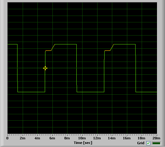
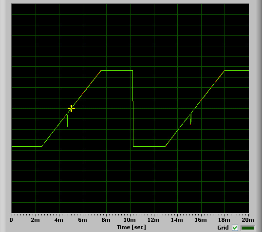
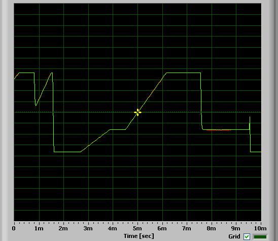
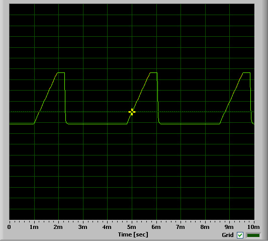
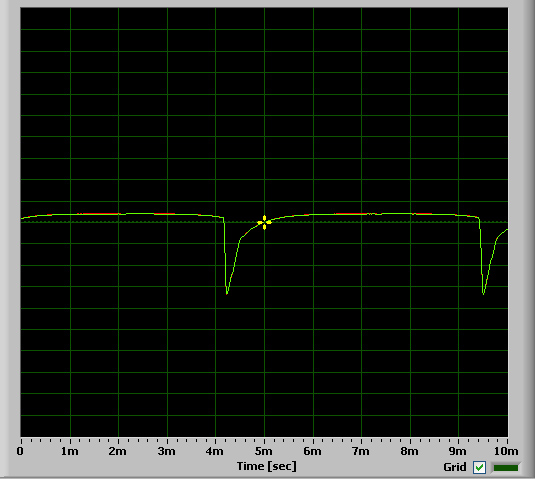
This got mentioned in the chat today, and decided to try and make a software version of the WaveWiper. I'm not sure I made exactly the same thing ... but it turned out to be quite a nice wave shaper 
The image below is a triangle and a square wave on inputs 1 and 2, with a sine wave on the CV / Break input. Viewing outputs 1 and 2.

_________________
Jan
also .. could someone please turn down the thermostat a bit.
 |
|
|
Back to top
|
|
|
diablojoy
Joined: Sep 07, 2008
Posts: 809
Location: melbourne australia
Audio files: 11
|
| Posted: Wed Jun 17, 2015 1:02 am Post subject:
|
|
|
nice seems a little more ideal perhaps
I really should relook into this got distracted by numerous other bright shiny things.
maybe I could do a proper board now
_________________
In an infinite universe one might very well
ask where the hell am I
oh yeah thats right the land of OZ
as good an answer as any |
|
|
Back to top
|
|
|
elmegil

Joined: Mar 20, 2012
Posts: 2179
Location: Chicago
Audio files: 16
|
| Posted: Wed Jun 17, 2015 7:26 am Post subject:
|
|
|
| diablojoy wrote: | nice seems a little more ideal perhaps
I really should relook into this got distracted by numerous other bright shiny things.
maybe I could do a proper board now |
I'd certainly be interested in one..... |
|
|
Back to top
|
|
|
|

 Forum index » DIY Hardware and Software