| Author |
Message |
Scott Stites
Janitor


Joined: Dec 23, 2005
Posts: 4127
Location: Mount Hope, KS USA
Audio files: 96
|
 Posted: Sun Nov 18, 2007 8:33 pm Post subject: Posted: Sun Nov 18, 2007 8:33 pm Post subject:
|
  |
|
I'm on dial-up, and I've loaded the file twice - takes about thirty to forty minutes each time I load it. If a post comes through while it's loading, the software will tell me that a post has occured, I go ahead and submit, and the attachment is gone, and I'm back to square one. 
_________________
My Site |
|
|
Back to top
|
|
 |
vtl5c3
Joined: Sep 08, 2006
Posts: 425
Location: PDX
Audio files: 13
|
| Posted: Sun Nov 18, 2007 10:49 pm Post subject:
|
|
|
I just spent the last half hour wondering about this.... "Why can't I find R23-26 on the board.... oh... there's already resistors stuffed in there... which one's right?!? 6.8K or 100K?!?" 
Thanks for the correction, Etaoin.
Anybody else get auto-unsubscribed from this thread? I haven't gotten any notifications about new posts for several weeks.
| Etaoin wrote: | Build manual page 75 and 76, the list of 100k resistors is the same as the list of 6k8 resistors...
6k8 list should probably be R32-R47. |
|
|
|
Back to top
|
|
|
Scott Stites
Janitor
Joined: Dec 23, 2005
Posts: 4127
Location: Mount Hope, KS USA
Audio files: 96
|
| Posted: Sun Nov 18, 2007 11:12 pm Post subject:
|
|
|
 So did the right one's get put in initially or.....not ? (hope I didn't send you reaching for your desoldering bulb). So did the right one's get put in initially or.....not ? (hope I didn't send you reaching for your desoldering bulb).
Occasionally I get unsubscribed from a thread; I've never figured out a rhyme or reason to it.
_________________
My Site |
|
|
Back to top
|
|
|
Scott Stites
Janitor
Joined: Dec 23, 2005
Posts: 4127
Location: Mount Hope, KS USA
Audio files: 96
|
|
|
Back to top
|
|
|
Scott Stites
Janitor
Joined: Dec 23, 2005
Posts: 4127
Location: Mount Hope, KS USA
Audio files: 96
|
|
|
Back to top
|
|
|
vtl5c3
Joined: Sep 08, 2006
Posts: 425
Location: PDX
Audio files: 13
|
| Posted: Mon Nov 19, 2007 1:35 pm Post subject:
|
|
|
| Scott Stites wrote: | So did the right one's get put in initially or.....not ? (hope I didn't send you reaching for your desoldering bulb).
Occasionally I get unsubscribed from a thread; I've never figured out a rhyme or reason to it. |
the right ones (100K) were already in place. Just stuffing the board at this stage, so no harm would have been done had the wrong ones been in their place. No harm done. If I had been angry, your latest two tracks would have been more than adequate compensation  |
|
|
Back to top
|
|
|
jonkull
Joined: Sep 22, 2006
Posts: 164
Location: Burbank, CA
|
|
|
Back to top
|
|
|
EdisonRex
Site Admin

Joined: Mar 07, 2007
Posts: 4579
Location: London, UK
Audio files: 172
|
| Posted: Mon Nov 19, 2007 4:49 pm Post subject:
|
|
|
Jon, that's quite an evolution. I see what you are thinking though. The groupings of the i/o jacks and the left hand side is nicely thought out. This is why I love DIY, people take ideas and run with them. That is the spirit.
Now, the main control surface... yeah, the linear with offset switches. This was where I started, actually.
From a usability point of view, there are two things I care about. One, will my fingers fit/will the parts collide, and two, can I find things intuitively.
I don't see a problem with the intuitive groupings (why should I :p) but the main issue I had was spacing the switches close enough to save space (hence the diagonal grouping) and yet not in the way of the main knobs. The issue is those main knobs will be used a LOT and not a lot else will.
I went for the radial pattern to open up hand space. I intend to try a mockup before I build, by the way. I can already tell that the blue LEDs will make a nice chase pattern, but I want to make sure I can work the controls. On this design, it looks much more compact, which is fine, just make sure your fingers aren't colliding with those bat switches.
_________________
Garret: It's so retro.
EGM: What does retro mean to you?
Parker: Like, old and outdated.
Home,My Studio,and another view |
|
|
Back to top
|
|
|
jonkull
Joined: Sep 22, 2006
Posts: 164
Location: Burbank, CA
|
| Posted: Mon Nov 19, 2007 5:16 pm Post subject:
|
|
|
| EdisonRex wrote: | | Jon, that's quite an evolution. I see what you are thinking though. The groupings of the i/o jacks and the left hand side is nicely thought out. This is why I love DIY, people take ideas and run with them. That is the spirit. |
Well what originally inspired me was the diagonal arrangement you chose for the 16 knobs. What's funny is that that's the one thing I couldn't carry over to this design. I'm also in love with design of the Future Retro Revolution and Genoqs Octopus which is where my white with wood ends and metal knobs inspiration came from. I tried a circular UI but that didn't quite work. Too much wasted space.
| EdisonRex wrote: | From a usability point of view, there are two things I care about. One, will my fingers fit/will the parts collide, and two, can I find things intuitively.
I don't see a problem with the intuitive groupings (why should I :p) but the main issue I had was spacing the switches close enough to save space (hence the diagonal grouping) and yet not in the way of the main knobs. The issue is those main knobs will be used a LOT and not a lot else will. |
I may have to play with the spacing of the switches. They're way too close to the knobs and eachother. By the way...does anyone know if it's possible to use some kind of push buttons instead of switches?
| EdisonRex wrote: | | I went for the radial pattern to open up hand space. I intend to try a mockup before I build, by the way. I can already tell that the blue LEDs will make a nice chase pattern, but I want to make sure I can work the controls. On this design, it looks much more compact, which is fine, just make sure your fingers aren't colliding with those bat switches. |
I wanted to go with a desktop version as I have no rack gear and therefore no rack. Right now it's designed to be a 12"x12" square. After seeing the size of the PCBs I thought about doing a mini-version of the Klee even smaller than 12x12 but decided against it for ergonomic reasons. What I'll probably do is make a cardboard mock-up once I decide on what kind of knobs/switches I want and then go from there. At this point I'm just hoping I can get this to work with my Voyager and Little Phatty. I think I'm going to need some kind of attenuator to get the proper voltage from the Klee into them. I'll burn that bridge when I get to it though. If it doesn't work it'll at least be a fun build.
Thanks for the tips. |
|
|
Back to top
|
|
|
EdisonRex
Site Admin
Joined: Mar 07, 2007
Posts: 4579
Location: London, UK
Audio files: 172
|
| Posted: Mon Nov 19, 2007 5:34 pm Post subject:
|
|
|
Your Voyager and Little Phatty will work just fine with this.
It must be a luxury to have desktop space! I have so little horizontal space I have to be extremely careful what goes where. Everything is arranged.
_________________
Garret: It's so retro.
EGM: What does retro mean to you?
Parker: Like, old and outdated.
Home,My Studio,and another view |
|
|
Back to top
|
|
|
jonkull
Joined: Sep 22, 2006
Posts: 164
Location: Burbank, CA
|
| Posted: Mon Nov 19, 2007 5:59 pm Post subject:
|
|
|
| EdisonRex wrote: | Your Voyager and Little Phatty will work just fine with this.
It must be a luxury to have desktop space! I have so little horizontal space I have to be extremely careful what goes where. Everything is arranged. |
I don't have much space I'm just (like you) careful with what goes where. To be honest, I'm not even sure where I'm going to put the Klee when I build it . |
|
|
Back to top
|
|
|
jksuperstar

Joined: Aug 20, 2004
Posts: 2503
Location: Denver
Audio files: 1
G2 patch files: 18
|
| Posted: Mon Nov 19, 2007 6:01 pm Post subject:
|
|
|
I'm going to try to take notes from the JL Cooper CS-32 mini midi controller. I've always loved packing a monster in a gerbil cage.
http://www.sonicstate.com/features/article.cfm?id=63
If the switches were push-on push-off kind, they may work as a replacement, good idea for space & finger room! |
|
|
Back to top
|
|
|
blue hell
Site Admin

Joined: Apr 03, 2004
Posts: 24606
Location: The Netherlands, Enschede
Audio files: 310
G2 patch files: 320
|
| Posted: Mon Nov 19, 2007 6:25 pm Post subject:
|
|
|
| jksuperstar wrote: | | If the switches were push-on push-off kind, they may work as a replacement, good idea for space & finger room! |
Scott had a note about that, think in the build docs, about toggles giving more visual feedback - but of course there are these fish eye switch thingies to solve that, or lights 
_________________
Jan
also .. could someone please turn down the thermostat a bit.
 |
|
|
Back to top
|
|
|
Randaleem
Joined: May 17, 2007
Posts: 456
Location: Northern CA, USA
|
| Posted: Mon Nov 19, 2007 6:34 pm Post subject:
|
|
|
| jonkull wrote: | | As I've never designed a panel before I have some questions. First...how do you know how far to space things? |
Hi Jonkull,
You can look at other people's designs to get an idea of how much space is condsidered enough, Or you can mock up your panel using cardboard and real parts to check its viability for your use. A combination of the two methods is probably best. There are quitre a few .fpd files available for various synth modules, and you can learn a lot by looking at these in the native Front Panel Designer free layout program.
| Quote: | | but how do you know how much room you need on the back of the panel where all the components and wires are? |
Create a drawing of the part outline and include it in your layout. I've lately been using the free program Front panel designer, and for example, have drawn a .320 x .510 white rectangle to represent an SPDT toggle switch. This way I can see what room is needed for this type switch behind the panel. There is also of course the front panel black circle representing the switch nut.
I use a .648 black circle to represent the knobs which is near the size of the knob skirt, but really is there to show the size of the typical Alpha 16mm Pot I have generally in mind to use.
FWIW, In your panel, I think you will have problems with the switched located above the knobs. They are so close that you'll have to use a fingernail kind of approach to toggle them away from the pot knob. (It will be no problem to toggle them trowards the knob!) I also believe a separation between the pattern switches and gatebus switches is more effective at helping to see what you've got going on with your Klee. Fortunately, these two ideas can work together. If you place the 2 switches associated with each knob to th eleft or right of it, with one above and one below, you now have room and separation. the knob can be gripped horizontally, and the switch toggles are far enough from each other that yo can switch one or the other at will.
I'd also like to comment upon the single lefthand vertical row of single switches for control purposes. I don't think it is an especially ergonomic solution.
If you look at things which involve lots of switches that need to be quickly and accurately switched (space capsules, aircraft panels, nuclear reactor panels, traffic control command centers) you will find horizontal groups of switches, usually two, three or four per group, sometimes 5. Often these groups are indicated with a color change so that additional spacing between groups is unnecessary.
This is because people in these industries have learned over the years that a single row of switches thus arranged may be manipulated more accurately AND allows for more than one switch to be thrown within the same hand motion. Think also of the old desktop computers like the IMSAI 8080 I first learned to program with. We were setting 4 digits at a time (hex input) with single hand motions. Try to set any two at the same time with the vertical switch arrangement you have followed...
The Klee is a very PLAY-able seq, and if you think about how you might best achieve this, you will naturally put certain groups of switches together to enhance this play-ability. For example, putting the three merge switches in a horizontal group allows one to effect simple and complex changes to a greater degree than having them above each other in a single line.
The 1x16/2x8 and invertB switches are similarly associative in their actions.
Think of what your left hand will be doing while your right hand is doing... And vice versa. The klee is not a typical set-and-forget kind of seq., so these choices now can greatly affect what you are able to achive in "playing" it.
Separate from the klee, when designing a panel, reach towards it (virtually) imagining it in its "in use" positions. Look at how your fingers are aligned and how your wrist is oriented. This will show you in which of several directions you need to have "clearance". If you are designeing for others, or for unknown in use positions, then reach out with both hands to simulate a variety of virtual positions.
Also, you will find that most "technical" toggle switch locations use an up/down action as opposed to side to side. This is again more ergonomic, based on studies over a long time in situations demanding quickness and accuracy.
| Quote: | | Second, I would like to have the whole thing be gray on white (as shown). Can this be done from a manufacturing point of view or should I simplify my design? |
Yes, it can be done. White screen printed ink on gray background paint or vice versa.
| Quote: | | Last, does anyone know a good online source of knobs (in the US...with pictures preferably)? I'd like to use metal knobs if possible. |
This depends upon your quantity and timeframe. For a small order (like an individual Klee) you are best to use the standard distributors and surplus sources. Mouser, Digikey, Allied, Alltronics, etc in the USA. If you can put together a largish order (and with modular synths this is a real possibility) then you can often go direct to the mfr. Alpha in southern California is one distibutor/MFR. Ebay has a few Asian sellers with large knob inventories. Allpartspipe is one such seller. While there have been some with issues anbout these Asian Ebay sellers WRYT chips, everyone I've seen so far has gotten their knobs without incident.
Another possibility with metal knobs is to have them made by a jobshop machinist. I made the knobs for my first modular synthesizer in High School metalshop. I wasn't actually in metalshop(Having built the walnut moog style synth cabinet in wood shop), but the Metals teacher appreciated my interest and need and helped me to learn a great deal about lathes in the process. These knurled aluminum knobs were unique, and something similar can still be done today.
Nowadays many cities have hobbyist machinist groups you can find online, where you may find a home shop machinist willing to take on your project at less than normal rates. Or in smaller qty than would be feasible for a commercial jobshop.
Kind regards, Randal |
|
|
Back to top
|
|
|
Randaleem
Joined: May 17, 2007
Posts: 456
Location: Northern CA, USA
|
| Posted: Mon Nov 19, 2007 6:38 pm Post subject:
|
|
|
| jksuperstar wrote: | | I've always loved packing a monster in a gerbil cage. |

| Quote: | | If the switches were push-on push-off kind, they may work as a replacement, good idea for space & finger room! |
And also very play-able! Might choose ones with an integral LED to indicate on/off position at a glance without requiring panel space.
Kind regards, Randal |
|
|
Back to top
|
|
|
Luka

Joined: Jun 29, 2007
Posts: 1003
Location: Melb.
|
| Posted: Tue Nov 20, 2007 6:28 am Post subject:
|
|
|
hey crew
ok, so this is the first panel i have actually designed myself, i would love some feedback regarding how yall think it will fit into a modular system.
yup thats right, this is not desktop, its a 5x9U panel.
I orginally went for the circular but found it hard to work with the buss, it just got awkward and it looked like starship enterprise hehe
so this is it, this unit will be on my bottom cabinet so i placed the INs toward the top left, OUTs on the left hand side and tried to keep all my controls out of the way of patch cords, and also tried to make it so you could operate one side with one hand and the other with the other.

im thinking the left hand side is a bit crazy and all over the place, or am i just being too pedantic?? would love to hear your thoughts
_________________
problemchild
melbourne australia
http://cycleofproblems.blogspot.com/
http://www.last.fm/user/prblmchild |
|
|
Back to top
|
|
|
Randaleem
Joined: May 17, 2007
Posts: 456
Location: Northern CA, USA
|
| Posted: Tue Nov 20, 2007 7:08 am Post subject:
|
|
|
| Luka wrote: | | i would love some feedback regarding how yall think it will fit into a modular system. would love to hear your thoughts |
Hi Luka!
I think it looks very nice! I really like the way you've orchestrated the gatebus graphics!
The only thing I'd think could be a concern is the merge switches so close to their jacks. Especially in a MOTM format where the patch cable plug ends stick so much farther out than the switch toggles.
So when you have it patched up, your left hand will have a rough go of it in getting to those three switches, I'm thinking.
You might want to "slide them down the graphics" into the area under the step and load buttons. If you stagger them horizontally in that area (but still on their "given" bus line graphic), they'll make a nice sloped effect, and be more easily used IMO. That also puts them in the vicinity of the 1x16/2x6 and Inv B switches for some of that single hand multiple switch effecting I wrote about above.
Two other things; only one of which is ergonomic per se. You may want the pattern switches a bit further from their pots?
And finally, it might be really interestng to have all 16 stage LEDs in the center of the panel between the two "legs" of the gatebus graphic lines. They'll still "associate" to their respective pots and pattern switches I think, will obviously more closely correlate to the gatebus switching (which I think is a help), and will be visually stunning by their more coherent overall effect.
Great looking work!
Kind regards, Randal |
|
|
Back to top
|
|
|
jonkull
Joined: Sep 22, 2006
Posts: 164
Location: Burbank, CA
|
| Posted: Tue Nov 20, 2007 11:14 am Post subject:
|
|
|
@ Randaleem...your response to my post gave me a lot to think about. Thanks for the help.
Jon |
|
|
Back to top
|
|
|
THeff

Joined: Sep 01, 2006
Posts: 229
Location: Florida
Audio files: 33
|
| Posted: Tue Nov 20, 2007 1:21 pm Post subject:
MPS / Klee samples |
|
|
Hey Scott,
I just listened to your latest MPS samples and they are way cool! The Mechanobalism sample would definitely make the Cubans start dancing here in South Florida!
My favorite is the Kleestralian! There is kind of a cool PVC tube sound in there,  but the 60 Hz electrocution sound is a little frightening but the 60 Hz electrocution sound is a little frightening 
Keep em coming...
Tim |
|
|
Back to top
|
|
|
Luka
Joined: Jun 29, 2007
Posts: 1003
Location: Melb.
|
|
|
Back to top
|
|
|
Scott Stites
Janitor
Joined: Dec 23, 2005
Posts: 4127
Location: Mount Hope, KS USA
Audio files: 96
|
| Posted: Tue Nov 20, 2007 7:04 pm Post subject:
|
|
|
Thanks Tim
"Kleestralia" was what I had to record before I took those current measurements for Thomas for the locked mode on the MPS. Once I was done with those, I used the same patch to create that locked sample over on the TH forum - different settings, but the electrocution is still there.
Romeo: Glad to know you didn't have to desolder. Of all the mistakes, that one couldn't have been in a worse spot. I'm glad Etaoin found it so quickly.
All: Very cool panels, indeed!
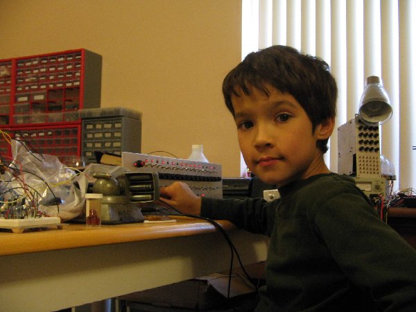
Sunday, Igor was complaining about how bored he was, so I turned him loose on the Klee. He had a great time with it, and actually produced a few sequences that left me envious of the little squirt.
| Description: |
|
| Filesize: |
206.01 KB |
| Viewed: |
185 Time(s) |
| This image has been reduced to fit the page. Click on it to enlarge. |

|
| Description: |
|
| Filesize: |
229.28 KB |
| Viewed: |
182 Time(s) |
| This image has been reduced to fit the page. Click on it to enlarge. |
|
_________________
My Site |
|
|
Back to top
|
|
|
THeff
Joined: Sep 01, 2006
Posts: 229
Location: Florida
Audio files: 33
|
| Posted: Tue Nov 20, 2007 8:10 pm Post subject:
Klee & Igor Pictures |
|
|
Hey Scott,
I finally remembered the name of the Aborigines instrument that your Kleestralian sample emulates...a didgeridoo. The only thing that I could picture at the time was a long piece of PVC tubing. That sample really does have a down under sound.
Do I see the MPS breadboard on the left side of the Igor / Klee pictures?
Tim |
|
|
Back to top
|
|
|
Scott Stites
Janitor
Joined: Dec 23, 2005
Posts: 4127
Location: Mount Hope, KS USA
Audio files: 96
|
| Posted: Tue Nov 20, 2007 9:02 pm Post subject:
|
|
|
Funny, I thought it had kind of an Australian groove to it, too, though I'm sure the Australians would disagree . Sort of a "Men At Work" beat, I suppose. Of course, if I were to imitate any Australian band, it would be early Icehouse. "Icehouse" and "Primitive Man" both had a huge impact on me when they came out - that Iva Davies had his synth shit together, in my book. They still rank among my all-time faves.
No - that breadboard is one of Thomas' summer projects - either the VCA or the VCO. I robbed a pot from them here or there, and I have to re-check them before I can put them back into service. I need to do that. That VCO did a pretty good turn for the bass line in the "Do You Klee" sample.
Anyway, here's a pic of the "Kleestralia" patch (same one as the "Mechanobalism" and "Locked MPS" samples I did this weekend). The breadboard in front of the synth is the MPS. The circuit isn't as scary as that thing looks. Photon might recognize the breadboard .
On the synth, the far left module is the triple Wilson EG. The row of switches on it consists of the time constant switch for each EG. Down is a fast time constant, middle is medium, and up is long. Basically, each switch just puts more capacitance in parallel with the timing cap. I can't begin to stress how much I use those switches. Like the zappifying sound in "Kleestralia" - it's actually the same voice as the "whacka" sound that accompanies the MPS and UD-1 to form the percussive element in the sample. When I flip the EG timing switch from short to medium, it holds the filter (MS-20 Clone in HP mode) open longer, as well as its VCA, which lets the signal through for longer, which creates the zappifier. The signal for that is a triangle wave through the CGS Wave Multiplier, with an audio rate LFO modulating the Folds CV. I use those switches all the time with the Klee. Combining those positions with the Merge Switch settings provides a huge amount of variation out of a single Klee pattern. The Klee merge switches, BTW, brought in the MPS toms and UD1 Bass in and out on "Mechanobalism". The triggers would fire much more often when busses 1 and 3 were unmerged.
The module with the red knobs is the mixer module, which I use to fade the voices in and out on these Klee samples. It's a 4X1X2 mixer, and I've waxed on and on about its plethora of functions before. In this patch, there are seven inputs to the module (though I never used the DSC2000, which is patched into mixer B, input 3)). Each 4X1 mixer has its own output, and there is an "A+B" output used in this patch to output the combined output, which is required for this many inputs. The red knobs control the level of inputs 3 and 4 for each mixer. With no signal patched into their respective inputs, they will supply a +V offset or a -V offset (3 is +V, 4 is -V). I made the knobs red to remind me that they will be doing something if not full CCW with no input to their jacks.
The VCOs are to the right of the modular - they're just PCBs with no home. I've gotten so used to using them like that, well.....
In the Igor pics, the big module sitting on the bench supply is the Triple Wilson SVVCF - my U count on the rack is such that there's no room for it until I start a second rack.
Cheerio,
Scott
Edit: The small white breadboard on the left is the UD-1 - breadboarded for well over a year, and still ticking.....
| Description: |
|
| Filesize: |
481.56 KB |
| Viewed: |
196 Time(s) |
| This image has been reduced to fit the page. Click on it to enlarge. |

|
_________________
My Site |
|
|
Back to top
|
|
|
THeff
Joined: Sep 01, 2006
Posts: 229
Location: Florida
Audio files: 33
|
| Posted: Tue Nov 20, 2007 10:19 pm Post subject:
Breadboards |
|
|
Wow Scott,
Thanks for the picture of the breadboards. I like your "star ground" on the left side with the green aligator clips!
Tim |
|
|
Back to top
|
|
|
Dave Kendall

Joined: May 26, 2007
Posts: 421
Location: England
Audio files: 3
|
| Posted: Wed Nov 21, 2007 4:55 am Post subject:
|
|
|
Hi
Couldn't resist posting some anagrams - hope this is not *too* OT ....
electro-music Klee Sequencer:
Sleek, queer ol' eccentric muse.......
electro-music Klee:
meek electric soul
electro-music synth diy forum:
Hmm, see fun old circuitry toys........
Ohms deficiency = tumult, sorry!
Slithery, fumy semiconductor
Touchily unreformed mystics
So, my old circuitry theme's fun!
Cheers,
Dave |
|
|
Back to top
|
|
|
|

 Forum index » DIY Hardware and Software » Klee sequencer


