| Author |
Message |
Uncle Krunkus
Moderator

Joined: Jul 11, 2005
Posts: 4761
Location: Sydney, Australia
Audio files: 52
G2 patch files: 1
|
 Posted: Wed Jul 22, 2009 7:57 am Post subject: Posted: Wed Jul 22, 2009 7:57 am Post subject:
|
  |
|
I felt like I should have responded with a resounding "yes it is" (seeing as how I laid it out!  ) )
But the fact was that I double guess myself so much that I quickly convinced myself that I just wasn't as sure as I thought I was! 
_________________
What makes a space ours, is what we put there, and what we do there. |
|
|
Back to top
|
|
 |
Funky40
Joined: Sep 24, 2005
Posts: 875
Location: Swiss
Audio files: 1
G2 patch files: 5
|
| Posted: Wed Jul 22, 2009 7:59 am Post subject:
|
|
|
I'm very confused about the shell CV in and the optional CV ins ( impact/ Noise )
my shell CV in is definitly not working.
looking to Bugs wiring table it looks now to me as the switch should be a on-on-on and not on-on as i have.
I also messed up my panel while building the module because i added a CV input for the noise,
but then there was no J21 connector on the board....
buit now i remember that there was some disscussion somewhere back in this thread, and CV for noise and impact was omitted,
but then again i don't understand the lettering of the switch.
Is this switch thought to change the destination where that CV input goes to ?
i'm confused
the module sounds great, just wish to have a second one.
another faceplate is donne, another board too, but i have no connectors.......forgot to order those, shit ( must take them now over musikding )
thanks to Thomas, uncle K, Bugs and all the others involved in this project ! |
|
|
Back to top
|
|
|
Uncle Krunkus
Moderator
Joined: Jul 11, 2005
Posts: 4761
Location: Sydney, Australia
Audio files: 52
G2 patch files: 1
|
| Posted: Wed Jul 22, 2009 8:07 am Post subject:
|
|
|
There is only one CV in on the final board.
However, the "CV Source" or "shell modulation type" switch, lets you send the impact or noise signal into the CV summer for the shell. It's normaled to the Shell CV input jack.
_________________
What makes a space ours, is what we put there, and what we do there. |
|
|
Back to top
|
|
|
Funky40
Joined: Sep 24, 2005
Posts: 875
Location: Swiss
Audio files: 1
G2 patch files: 5
|
| Posted: Thu Jul 23, 2009 7:11 am Post subject:
|
|
|
| so i indeed need just a single pole switch and i just have to connect the center of the switch to the switch of the jack ? |
|
|
Back to top
|
|
|
Uncle Krunkus
Moderator
Joined: Jul 11, 2005
Posts: 4761
Location: Sydney, Australia
Audio files: 52
G2 patch files: 1
|
| Posted: Thu Jul 23, 2009 3:35 pm Post subject:
|
|
|
Yep
_________________
What makes a space ours, is what we put there, and what we do there. |
|
|
Back to top
|
|
|
Funky40
Joined: Sep 24, 2005
Posts: 875
Location: Swiss
Audio files: 1
G2 patch files: 5
|
| Posted: Fri Jul 24, 2009 5:34 pm Post subject:
|
|
|
switch is replaced/rewired.
thanks
i had bleedthru from the impact to the noise mix when i tested the module.
now, placed in the sYnth i hear nothing. works again fine
only thing what is not running is the impact to CV shell modulation.
noise is working as modulation.
Have to check that wire......
great, happy that this 18 Pot module is running. |
|
|
Back to top
|
|
|
Thomas_Henry
Joined: Jul 24, 2009
Posts: 170
Location: N. Mankato, MN
Audio files: 3
|
|
|
Back to top
|
|
|
mosc
Site Admin

Joined: Jan 31, 2003
Posts: 18284
Location: Durham, NC
Audio files: 235
G2 patch files: 60
|
| Posted: Thu Aug 06, 2009 8:58 am Post subject:
|
|
|
Welcome back, TH. Great to have you here. Hope to hear that new song that coming on...
_________________
--Howard
my music and other stuff |
|
|
Back to top
|
|
|
droffset

Joined: Feb 02, 2009
Posts: 515
Location: London area
Audio files: 2
|
| Posted: Thu Aug 06, 2009 2:40 pm Post subject:
|
|
|
Hi Thomas, good to see you.
I purchased the electronic drum cookbook and am about to embark on a MPS build(or four), thanks for releasing this stuff, lots of possibilities to play with.  |
|
|
Back to top
|
|
|
rudypoochris
Joined: Jul 16, 2009
Posts: 22
Location: Oakland, CA
G2 patch files: 1
|
| Posted: Thu Aug 06, 2009 11:16 pm Post subject:
|
|
|
Where are you all ordering reasonably priced potentiometers and corresponding knobs from (P/N's appreciated if available)? Thanks! =]
I just can't seem to figure out which knobs have "D-Hole" shafts and which don't. |
|
|
Back to top
|
|
|
Funky40
Joined: Sep 24, 2005
Posts: 875
Location: Swiss
Audio files: 1
G2 patch files: 5
|
| Posted: Mon Aug 10, 2009 9:06 am Post subject:
|
|
|
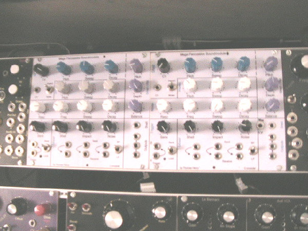
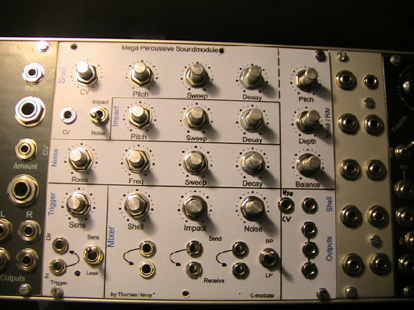
My MPS Eurorack panel.
messed it up with that additional Noise CV socket
thanks again, i like it !
for best adjustments i suggest to use "something" Multiturn. Trimmers for example instead of pots.
Especially for those who like to build several units.
Shell Pitch and RM pitch have lots of sounds within very small amounts of turning the Knob. ( Or the expensvie multiturns )
also Impact pitch could be donne multiturn, but not really important.
| Description: |
| 2x MPS in euroformat ( runing on +-15V |
|
| Filesize: |
94.58 KB |
| Viewed: |
420 Time(s) |
| This image has been reduced to fit the page. Click on it to enlarge. |
|
| Description: |
| my MPS panel in more clear |
|
| Filesize: |
124.27 KB |
| Viewed: |
479 Time(s) |
| This image has been reduced to fit the page. Click on it to enlarge. |
|
|
|
|
Back to top
|
|
|
dnigrin

Joined: Aug 20, 2009
Posts: 79
Location: USA
|
| Posted: Thu Aug 20, 2009 4:56 am Post subject:
|
|
|
I'm considering building an MPS as a tabletop unit, as a standalone synth. I can get triggers/CVs to it from my other gear, but I'll need a power supply. I saw the previous post from Uncle Krunkus about using a Power One supply, but it seems those are ~$50 which is too expensive for me.
Could someone recommend a good power supply design that I could find online that would give me the +/- 15V necessary to power the MPS?
Thanks... |
|
|
Back to top
|
|
|
creatorlars

Joined: Nov 26, 2007
Posts: 524
Location: Denton, TX
Audio files: 4
|
|
|
Back to top
|
|
|
dnigrin
Joined: Aug 20, 2009
Posts: 79
Location: USA
|
| Posted: Thu Aug 20, 2009 9:07 am Post subject:
|
|
|
| Excellent, thanks! |
|
|
Back to top
|
|
|
hobgob_inc
Joined: Jun 09, 2009
Posts: 46
Location: Australia
|
| Posted: Sun Aug 23, 2009 4:56 pm Post subject:
|
|
|
Hey yall
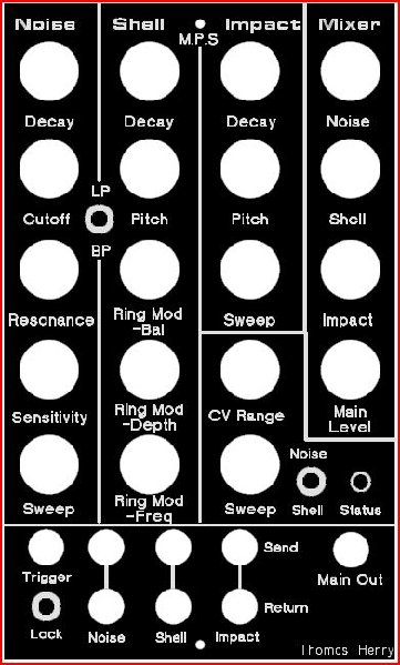
Just looking for some feed back on my panel design for the MPS. Thanks to all others who have posted theirs as inspiration.
I'm building two of these probably on blue anodize in a nice wooden casing. The size of the holes is actually representing the size of knobs, jacks etc. to give me an idea of the spacing, not the actual size of holes.
The main thing i've considered changing is dropping the send/receives. Any feedback would be great
Thanks, Luke[/img]
| Description: |
|
| Filesize: |
61.44 KB |
| Viewed: |
399 Time(s) |
| This image has been reduced to fit the page. Click on it to enlarge. |
|
| Description: |
|

Download (listen) |
| Filename: |
MegaPerc.fpd].pdf |
| Filesize: |
306.02 KB |
| Downloaded: |
504 Time(s) |
|
|
|
Back to top
|
|
|
hobgob_inc
Joined: Jun 09, 2009
Posts: 46
Location: Australia
|
| Posted: Sun Aug 23, 2009 4:58 pm Post subject:
|
|
|
Not sure how to have the image showing on the page....
| Quote: | | Edit: State Machine added image 8-27-09 .... saved the image in PDF as JPEG and used as attachment. The JPEG will automatically show up as an image in the post. |
|
|
|
Back to top
|
|
|
rudypoochris
Joined: Jul 16, 2009
Posts: 22
Location: Oakland, CA
G2 patch files: 1
|
|
|
Back to top
|
|
|
rudypoochris
Joined: Jul 16, 2009
Posts: 22
Location: Oakland, CA
G2 patch files: 1
|
| Posted: Wed Aug 26, 2009 9:27 pm Post subject:
|
|
|
| Eeek got another question, what is the difference between all the different grounds? There is an A-Gnd a D-Gnd and a P-Gnd on the board. Can these all be tied together? If not is A-Gnd AC ground and D Gnd DC ground? If that is so, does the unit have to be grounded to the AC wall outlet? Thanks for any support. |
|
|
Back to top
|
|
|
creatorlars
Joined: Nov 26, 2007
Posts: 524
Location: Denton, TX
Audio files: 4
|
| Posted: Wed Aug 26, 2009 10:01 pm Post subject:
|
|
|
| A-Gnd is analogue ground, D-Gnd is digital ground and P-Gnd is panel ground (wire to jack sleeves). I can't comment on the details of the wiring, but my guess is they are probably all connected on the board already at certain points. |
|
|
Back to top
|
|
|
Uncle Krunkus
Moderator
Joined: Jul 11, 2005
Posts: 4761
Location: Sydney, Australia
Audio files: 52
G2 patch files: 1
|
| Posted: Thu Aug 27, 2009 1:23 am Post subject:
|
|
|
Yes,
AGnd and DGnd are for systems which have separate Analogue and Digital ground run from their power supplies, so if you have only one ground from your PSU, just run it to the AGnd connection and leave J20 just as it is. (separate grounds need the link under J20 to be cut)
PGnd is just a termination I included for the wire which delivers ground to your front Panel.
_________________
What makes a space ours, is what we put there, and what we do there. |
|
|
Back to top
|
|
|
rudypoochris
Joined: Jul 16, 2009
Posts: 22
Location: Oakland, CA
G2 patch files: 1
|
| Posted: Thu Aug 27, 2009 1:42 am Post subject:
|
|
|
Ah okay got it, so leave J20 unsoldered since AGnd and DGnd will be joined?
Thanks for the assistance! |
|
|
Back to top
|
|
|
hobgob_inc
Joined: Jun 09, 2009
Posts: 46
Location: Australia
|
| Posted: Mon Aug 31, 2009 5:20 pm Post subject:
|
|
|
Thanks for doing that statemachine....
now anyone got any feedback for the MPS above??
Luke |
|
|
Back to top
|
|
|
janvanvolt

Joined: Nov 24, 2005
Posts: 285
Location: Mainz, Germany
|
|
|
Back to top
|
|
|
creatorlars
Joined: Nov 26, 2007
Posts: 524
Location: Denton, TX
Audio files: 4
|
|
|
Back to top
|
|
|
janvanvolt
Joined: Nov 24, 2005
Posts: 285
Location: Mainz, Germany
|
|
|
Back to top
|
|
|
|

 Forum index » DIY Hardware and Software » Thomas Henry designs


