| Author |
Message |
State Machine
Janitor


Joined: Apr 17, 2006
Posts: 2810
Location: New York
Audio files: 24
|
 Posted: Sat May 03, 2008 6:41 am Post subject: Posted: Sat May 03, 2008 6:41 am Post subject:
|
  |
|
Ole,
Nice job ..... I love the display cryptics .... adds much appeal. Nice additions also (filter, etc ...).
I have 3 of the PIC IC's in the wait so I can build one myself. Just have to finish up on a product release.
I assume sound samples are next ... 
Bill |
|
|
Back to top
|
|
 |
Joel
Joined: Sep 12, 2006
Posts: 97
Location: London, UK
|
 Posted: Sat May 03, 2008 8:18 am Post subject: Posted: Sat May 03, 2008 8:18 am Post subject:
|
  |
|
| okvern wrote: | | Here's my version. I had to add a filter (a state variable SEM clone, thanks to Takeda-san and MFOS), an LFO, and a tiny button keyboard. |
That looks amazing!! Do you have a link to the filter schematics? What does the little keyboard do? Looking forward to hearing how it sounds  |
|
|
Back to top
|
|
 |
okvern
Joined: Feb 05, 2008
Posts: 78
Location: Seattle, Washington
Audio files: 5
|
 Posted: Sat May 03, 2008 1:36 pm Post subject: Posted: Sat May 03, 2008 1:36 pm Post subject:
|
  |
|
Hi Joel, Bill,
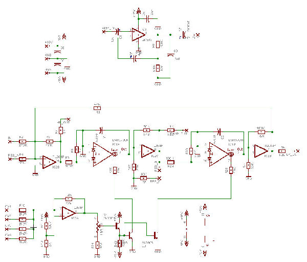
First, the state variable filter design and board--you can find the basic circuit at MFOS (http://www.musicfromouterspace.com/analogsynth/statevariablefilter.html) or at Takeda-san's site (http://www.aleph.co.jp/~takeda/radio/SVVCF.html). I've attached my version of the schematic (this board also included a small audio amp--after I made the board, I decided that the amp should go in the mask, so I sawed that part of the board off). My version of the schematic is based on Takeda-san's layout--I had slightly different parts, so I created an Eagle version to match. (His board layouts are great, by the way, and well worth studying!)
Attached files:
PICSynthBoards.zip: The main board and filter board, as 600ppi bilevel TIFFs. You'll need to look at the Eagle layouts for parts placement.
PICSynthFilterAmp.zip: Eagle .brd and .sch files for the state variable filter/amp board.
PICSynthBoard.zip: Eagle .brd and .sch files for the main board. Note that the LED display I used is pretty weird--you'll probably want to edit to add something more standard (I had some of these lying around).
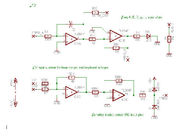
PICSynth_AddOnBoard.jpg: schematic of the LFO/CV summer circuit (I built this on a breadboard--didn't do an Eagle layout)
PICSynthFilterAmp.jpg: Schematic of my version of the state variable filter/amp board.
Note on the Eagle boards: When you open them, you'll need to hit the "Ratsnest" button to get the ground planes to fill in (if you don't, it'll look like a lot of things that should connect to GND don't connect).
Hope these are useful! I also want to thank catweazle/Eric for his incredible synth design!
I'll post sounds and other stuff soon.
Thanks,
Ole
| Description: |
|
| Filesize: |
103.34 KB |
| Viewed: |
945 Time(s) |
| This image has been reduced to fit the page. Click on it to enlarge. |

|
| Description: |
|
| Filesize: |
58.69 KB |
| Viewed: |
878 Time(s) |
| This image has been reduced to fit the page. Click on it to enlarge. |

|
| Description: |
|

Download (listen) |
| Filename: |
PICSynthBoard.zip |
| Filesize: |
30.01 KB |
| Downloaded: |
918 Time(s) |
| Description: |
|

Download (listen) |
| Filename: |
PICSynthFilterAmp.zip |
| Filesize: |
16.66 KB |
| Downloaded: |
828 Time(s) |
| Description: |
|

Download (listen) |
| Filename: |
PICSynthBoards.zip |
| Filesize: |
93.77 KB |
| Downloaded: |
857 Time(s) |
|
|
|
Back to top
|
|
 |
okvern
Joined: Feb 05, 2008
Posts: 78
Location: Seattle, Washington
Audio files: 5
|
 Posted: Sat May 03, 2008 1:40 pm Post subject: Posted: Sat May 03, 2008 1:40 pm Post subject:
|
  |
|
Fellow Builders,
I meant to mention--the +15v and -15v. supplies shown in the schematics are really +9v/-9v--everything is powered from two nine volt batteries, and battery life seems pretty good so far (now that I've exiled the LM383 to its own supply).
Thanks,
Ole |
|
|
Back to top
|
|
 |
okvern
Joined: Feb 05, 2008
Posts: 78
Location: Seattle, Washington
Audio files: 5
|
 Posted: Sun May 04, 2008 1:06 am Post subject: Posted: Sun May 04, 2008 1:06 am Post subject:
|
  |
|
Fellow Builders,
Here are a few samples. These are all straight out of the filter into Audition 3.0, no effects, nothing fancy. Envelopes are provided by me turning the volume knob (have to add an envelope generator and VCA next time!). The only other manual intervention is a bit of keyboard "playing" in one of the WSG examples.
Thanks,
Ole
| Description: |
|

Download (listen) |
| Filename: |
Fractal2_a.mp3 |
| Filesize: |
238.54 KB |
| Downloaded: |
1280 Time(s) |
| Description: |
|

Download (listen) |
| Filename: |
WSG_MiniKeyboard.mp3 |
| Filesize: |
433.35 KB |
| Downloaded: |
1143 Time(s) |
| Description: |
|

Download (listen) |
| Filename: |
Fractal1.mp3 |
| Filesize: |
580.49 KB |
| Downloaded: |
1191 Time(s) |
| Description: |
|

Download (listen) |
| Filename: |
FRactal1_b.mp3 |
| Filesize: |
535.33 KB |
| Downloaded: |
1132 Time(s) |
| Description: |
|

Download (listen) |
| Filename: |
Fractal2_b.mp3 |
| Filesize: |
404.24 KB |
| Downloaded: |
1120 Time(s) |
|
|
|
Back to top
|
|
 |
State Machine
Janitor


Joined: Apr 17, 2006
Posts: 2810
Location: New York
Audio files: 24
|
 Posted: Sun May 04, 2008 6:43 am Post subject: Posted: Sun May 04, 2008 6:43 am Post subject:
|
  |
|
Very cool ! Thanks for sharing all of this.  The SVF really adds the final touch to the project and provides some real nice movement to this sound generator. Perhaps a voltage controlled panner would also make a nice addition so that now you could have spatial FX as well. You can pan slowly or quickly for some nice "ping-pong" FX The SVF really adds the final touch to the project and provides some real nice movement to this sound generator. Perhaps a voltage controlled panner would also make a nice addition so that now you could have spatial FX as well. You can pan slowly or quickly for some nice "ping-pong" FX 
I listened to all the samples and the last one has some semblance of a melody 
This synthesizer could have some real appeal with the "chip music" crowd and "noise" artists. It also could add great ambiance for classic electronic "space music" by adding some reverberation. 
Thanks for posting the samples and other information. I have decided that mine will have such a filter and I will add a panning circuit also to the mix of additions. Thats as far as I will go with it just in case I want it to be battery powered and want to keep it simple. 
Bill |
|
|
Back to top
|
|
 |
okvern
Joined: Feb 05, 2008
Posts: 78
Location: Seattle, Washington
Audio files: 5
|
 Posted: Sun May 04, 2008 11:13 am Post subject: Posted: Sun May 04, 2008 11:13 am Post subject:
|
  |
|
Hi Bill,
I really like the WSG algorithm--you could probably reproduce most of the soundtrack for "Forbidden Planet" with it (and rest in peace Bebe Barron, one of the composers of that brilliant score--she died recently). It's definitely the "solo" instrument of the four synths in the design. It's also interesting to me because it still has two parameter pots to use up--I have to look at Eric's source code to see if more features could be added.
Yesterday I added an external CV in to the frequency input summing circuitry so that I can drive it from an external sequencer. I'm running out of places to add switches/jacks at this point--I think I'll add a jack for an external power supply and call it done.
Again, all credit to Eric for sharing this design with the community!
Thanks,
Ole
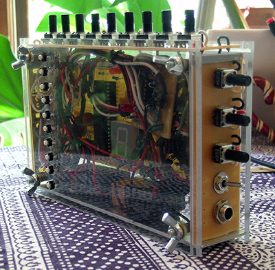
| Description: |
| Controls from top to bottom: filter frequency, filter resonance, filter LFO depth, low pass/bandpass switch, audio out |
|
| Filesize: |
257.89 KB |
| Viewed: |
42408 Time(s) |

|
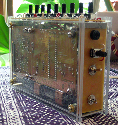
| Description: |
| From top to bottom: external CV input, LFO freqeuncy, reverse switch, space for external power jack, on/off switch |
|
| Filesize: |
245.57 KB |
| Viewed: |
42408 Time(s) |

|
|
|
|
Back to top
|
|
 |
YoSynthi
Joined: Aug 29, 2006
Posts: 26
Location: UK
|
 Posted: Sat May 10, 2008 3:44 am Post subject: Posted: Sat May 10, 2008 3:44 am Post subject:
|
  |
|
Oh dear,
I've just got hold of the appropriate PIC chips so that I can experiment with this project, but I've been unable to access the links at the start of the thread, with the source code and project description:
http://etecnic.fh-pforzheim.de/~catweazle/F-Synth/
Is the site / link dead? Does anyone have any of this stuff archived?
Catweazle? Anyone...? |
|
|
Back to top
|
|
 |
State Machine
Janitor


Joined: Apr 17, 2006
Posts: 2810
Location: New York
Audio files: 24
|
 Posted: Sat May 10, 2008 6:27 am Post subject: Posted: Sat May 10, 2008 6:27 am Post subject:
|
  |
|
| Quote: | | s the site / link dead? Does anyone have any of this stuff archived? |
I have confirmed the link is dead also. Might be a temporary thing  Ole has done his project and has been posting on this thread so he must have all the documentation, I am sure Ole has done his project and has been posting on this thread so he must have all the documentation, I am sure 
I can host the files on my web-space as a mirror if Ole sends all the documentation and code to me in a PM. I am sure the Cat-Wez will not mind ... 
Lets wait and see for a day or so first.
Bill |
|
|
Back to top
|
|
 |
catweazle
Joined: Feb 25, 2008
Posts: 28
Location: germany
Audio files: 3
|
|
|
Back to top
|
|
 |
okvern
Joined: Feb 05, 2008
Posts: 78
Location: Seattle, Washington
Audio files: 5
|
 Posted: Sat May 10, 2008 2:39 pm Post subject: Posted: Sat May 10, 2008 2:39 pm Post subject:
|
  |
|
Fellow Builders,
The party/rave/whatever is tonight! Everything is working, and (amazingly) I have not yet chickened out--the superhero named "The Oscillator" is ready to rock.
I ditched the LM383 version of the mini-amp, though, and advise everyone to not bother with that chip--it's unstable, hot, and just a nuisance. I built a Little Gem (http://runoffgroove.com/littlegem.html) instead, and it's great.
Glad you like the samples, Eric!
Thanks,
Ole
| Description: |
|
| Filesize: |
1.52 MB |
| Viewed: |
578 Time(s) |
| This image has been reduced to fit the page. Click on it to enlarge. |

|
|
|
|
Back to top
|
|
 |
State Machine
Janitor


Joined: Apr 17, 2006
Posts: 2810
Location: New York
Audio files: 24
|
 Posted: Sat May 10, 2008 8:59 pm Post subject: Posted: Sat May 10, 2008 8:59 pm Post subject:
|
  |
|
OK, here is a link to the PIC Based Fraktal Synth projatc files in case you cant get to the others. Just look for the file "picsynth_v11_191" in the list .....
http://statemachine.freehomepage.com/
Bill |
|
|
Back to top
|
|
 |
hanley
Joined: May 24, 2006
Posts: 27
Location: London
|
 Posted: Mon May 12, 2008 3:00 pm Post subject: Posted: Mon May 12, 2008 3:00 pm Post subject:
|
  |
|
| catweazle wrote: | Hello everyone!
I've developed that thing with the intention to have a versataile
simple lofi audio hardware to realize some unusual sounds.
Hardware:
- a cheap (yes, samples) 8bit microcontroller to be real lofi 
- 8 analog inputs / pots for parameters (CV in 0..5Volt)
- 1 analog output (Pulse with modulation) / audio out
(output is not filtered very well, add additional Filter / EQ + FX)
Software:
(sourcecode is available) http://etecnic.fh-pforzheim.de/~catweazle/F-Synth/
Documentation:
Ok, sourcecode could have more comments 
ask if questions
however it really makes crazy sounds 
and I'm very interested of your experiences (pics/sounds) ...
gtz
Eric
Edit:
use this schematic if you build it
http://etecnic.fh-pforzheim.de/~catweazle/F-Synth/PICsynth_V11_schematic.JPG |
hi catweazle
v impressed with you picsynth
does the pot value matter for the pots at there just for voltage dividing?
50k pots ok instaed of 10? |
|
|
Back to top
|
|
 |
okvern
Joined: Feb 05, 2008
Posts: 78
Location: Seattle, Washington
Audio files: 5
|
 Posted: Mon May 12, 2008 3:32 pm Post subject: Posted: Mon May 12, 2008 3:32 pm Post subject:
|
  |
|
Hi hanley,
They're just voltage dividers--I used 100K when I built it.
Thanks,
Ole |
|
|
Back to top
|
|
 |
hanley
Joined: May 24, 2006
Posts: 27
Location: London
|
 Posted: Fri Jun 20, 2008 1:28 am Post subject: Posted: Fri Jun 20, 2008 1:28 am Post subject:
|
  |
|
thanks the the info okvern
built this last week and other that confusing myself with some wiring it turned out great
i have a question for anyone who made/looked at the circuit design
the PWM output from the PIC has a resistor and cap on it

when i tried to send a signal though this it was almost inaudiable
without the resistor and cap is sounds fine
whats the purpose of this part of the circuit? |
|
|
Back to top
|
|
 |
catweazle
Joined: Feb 25, 2008
Posts: 28
Location: germany
Audio files: 3
|
 Posted: Fri Jun 20, 2008 3:51 am Post subject: Posted: Fri Jun 20, 2008 3:51 am Post subject:
|
  |
|
R7 and C1 form a RC-lowpass filter to filter out the PWM frequency.
C2 (~0.1uF) filter DC contents (audio inputs don't like DC voltages)
The R8 (470k) limits the signal (on my test the output signal was a bit strong for my mixer. you don't need the R8 really. |
|
|
Back to top
|
|
 |
catweazle
Joined: Feb 25, 2008
Posts: 28
Location: germany
Audio files: 3
|
|
|
Back to top
|
|
 |
okvern
Joined: Feb 05, 2008
Posts: 78
Location: Seattle, Washington
Audio files: 5
|
 Posted: Sat Jun 21, 2008 10:51 pm Post subject: Posted: Sat Jun 21, 2008 10:51 pm Post subject:
|
  |
|
Hi Eric,
The party was so loud that I couldn't hear myself, most of the time, even when I was *wearing the mask*. When we put it through a guitar amp and the PA, though, it was cool, and people dug it. It was quite the party. It's been a month, and I might still be hung over.
"The Oscillator" lives, and is currently set up next to my dining room table. We often consult him for advice, weather forecasts, etc. I am still exploring all of the stuff you built into that synth, and still discovering wonderful sounds. Again, excellent work! You rock.
Thanks,
Ole |
|
|
Back to top
|
|
 |
oootini

Joined: Oct 15, 2007
Posts: 80
Location: ireland
|
 Posted: Mon Jun 23, 2008 11:25 am Post subject: Posted: Mon Jun 23, 2008 11:25 am Post subject:
|
  |
|
don't suppose anyone has a veroboard layout of this?
looks like it might be time for me to build from a schematic...
*gulp. |
|
|
Back to top
|
|
 |
catweazle
Joined: Feb 25, 2008
Posts: 28
Location: germany
Audio files: 3
|
|
|
Back to top
|
|
 |
oootini

Joined: Oct 15, 2007
Posts: 80
Location: ireland
|
 Posted: Tue Jun 24, 2008 1:15 am Post subject: Posted: Tue Jun 24, 2008 1:15 am Post subject:
|
  |
|
| cool, thanks catweazle. reckon i'll invest in some perfboard then. can't wait to get stuck into this... |
|
|
Back to top
|
|
 |
State Machine
Janitor


Joined: Apr 17, 2006
Posts: 2810
Location: New York
Audio files: 24
|
 Posted: Tue Jun 24, 2008 3:42 pm Post subject: Posted: Tue Jun 24, 2008 3:42 pm Post subject:
|
  |
|
| Quote: | if you use a veroboard (stripe type board) then you have to
cut a lot more traces than using a Perfboard (with dots instead of stripes). |
Yes, I usually end up using "pad-per-hole" boards and is the way I like to breadboard circuits that are under development. I take wire wrap sockets , plug them into the board, and solder down each corner to add stability. This circuit is perfect for that as a nice 40 Pin DIP IC is used. 
When I get less busy I plan on building two Fractal synthesizers on a nice board I purchased from "Circuit Specialists".
Bill |
|
|
Back to top
|
|
 |
oootini

Joined: Oct 15, 2007
Posts: 80
Location: ireland
|
 Posted: Sat Jul 12, 2008 5:54 am Post subject: Posted: Sat Jul 12, 2008 5:54 am Post subject:
|
  |
|
have all my parts and a loaded pic chip and am gonna start on this today. questions:
r30 - r21 (the resistors on the numierical display - the schematic says they should be 200- 470 R. i presume this means that any res between these values will work yeah?
also, i've read in descriptions for other projects that the pot bodies should be grounded to prevent audible hum. i am going to be putting the completed citcuit into a plastic container. will this be a problem? woould a piece of tinfoil across all the pots be sufficient to stop this hum? |
|
|
Back to top
|
|
 |
catweazle
Joined: Feb 25, 2008
Posts: 28
Location: germany
Audio files: 3
|
 Posted: Sat Jul 12, 2008 11:04 am Post subject: Posted: Sat Jul 12, 2008 11:04 am Post subject:
|
  |
|
the resistors for the led display depends on the display used.
(on lower values the leds will be brighter)
if you power the device with batteries I recommend using higher values
(less current consumtion)
I never had problems with unshielded pots in other projects.
they are only voltage deviders so I think there is no shielding needed. |
|
|
Back to top
|
|
 |
oootini

Joined: Oct 15, 2007
Posts: 80
Location: ireland
|
 Posted: Sun Jul 13, 2008 4:48 am Post subject: Posted: Sun Jul 13, 2008 4:48 am Post subject:
|
  |
|
thanks catweazle. 
one more question: would this circuit work with a 9 volt battery? i have a 9v battery clip handy... |
|
|
Back to top
|
|
 |
|


