| Author |
Message |
fonik

Joined: Jun 07, 2006
Posts: 3950
Location: Germany
Audio files: 23
|
 Posted: Wed Oct 01, 2008 1:14 am Post subject: Posted: Wed Oct 01, 2008 1:14 am Post subject:
|
  |
|
nice shot!
these are precision ceramic disc caps? zero tolerance? i don't think you will experience any problems. leave them, they're looking quite good.
these are just filter caps to keep the voltage rails clean, so as said before, it does not matter IMO.
_________________

cheers,
matthias
____________
Big Boss at fonitronik
Tech Buddy at Random*Source |
|
|
Back to top
|
|
 |
LektroiD

Joined: Aug 23, 2008
Posts: 1019
Location: Scottish Borders
Audio files: 2
G2 patch files: 2
|
| Posted: Wed Oct 01, 2008 3:05 am Post subject:
|
|
|
| fonik wrote: | nice shot!
these are precision ceramic disc caps? zero tolerance? i don't think you will experience any problems. leave them, they're looking quite good.
these are just filter caps to keep the voltage rails clean, so as said before, it does not matter IMO. |
I assume these are precision caps, I got them when I was building aircraft communications boards nearly 20 years ago. They always let me have the leftovers from a run of boards, I still have a few left. I used poly caps for C1 & C2. |
|
|
Back to top
|
|
|
LektroiD
Joined: Aug 23, 2008
Posts: 1019
Location: Scottish Borders
Audio files: 2
G2 patch files: 2
|
|
|
Back to top
|
|
|
fonik
Joined: Jun 07, 2006
Posts: 3950
Location: Germany
Audio files: 23
|
| Posted: Wed Oct 01, 2008 6:50 am Post subject:
|
|
|
| Brainstormer wrote: | Since this is my first module, I have a couple of questions regarding connectivity...
The power source connector, there appears to be two, is this for choice, or do both need to be there? Is there a standard for modules? And what are the part numbers? |
these connectors are to be used alternatively. the 4-pin connectors is used by MOTM and Blacet (AFAIK), the 2x5-pin ribbon connectors are used by Doepfer, Analogue Solutions and Analogue Systems.
for the .156 grid 4-pin connectors search for molex or tyco .156 (farnell stocks them), for the ribbon connectors search ...err... ribbon connectors?
| Quote: | | Also, I have soldered pin connectors for the panel components, is this the standard procedure? I need to know what sockets I can buy to connect to the panel components to them? |
actually i indended to use crimped connectors. they need to be stackable. i like your idea of using simple pin connectors, though.
it would be good if others shared their practice here. i just try to use what i get at my supplier. you mileage may vary...
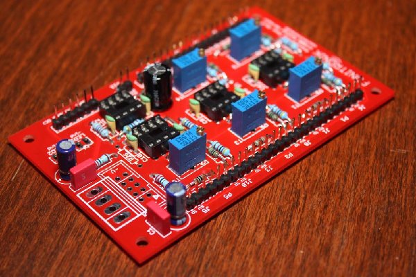
take a look at this picture below. this is a module i used those crimped connectors for. for the attenuverting mixer you need stackable connectors, like the two 3-pin connectors with blach caps (picture bottom, middle)

_________________
cheers,
matthias
____________
Big Boss at fonitronik
Tech Buddy at Random*Source |
|
|
Back to top
|
|
|
Kent

Joined: Mar 31, 2008
Posts: 53
Location: All over Europe & elsewhere (Mostly Paris)
|
| Posted: Sun Nov 09, 2008 5:03 am Post subject:
2 PCBs for Paris, France |
|
|
I'd like 2 of them please.
Thanks. |
|
|
Back to top
|
|
|
fonik
Joined: Jun 07, 2006
Posts: 3950
Location: Germany
Audio files: 23
|
| Posted: Sun Nov 09, 2008 7:05 am Post subject:
|
|
|
great. check your PMs, kent. 
_________________
cheers,
matthias
____________
Big Boss at fonitronik
Tech Buddy at Random*Source |
|
|
Back to top
|
|
|
Appliancide*

Joined: Jul 04, 2007
Posts: 126
Location: Paul lives in a 1920’s film
|
| Posted: Sun Nov 09, 2008 12:39 pm Post subject:
|
|
|
One of my IC sockets might be questionable. Can you tell me what voltages to look for before seating the ICs? The one I'm worried about is IC3.
Also is the one connection that is shown with a line on the pcb just a wire or is there something specific that I should use?
Sorry if this has all been covered, but this will be my first completed module so I want to make sure it's right before I power it up.
Thanks,
Paul |
|
|
Back to top
|
|
|
fonik
Joined: Jun 07, 2006
Posts: 3950
Location: Germany
Audio files: 23
|
| Posted: Sun Nov 09, 2008 2:16 pm Post subject:
|
|
|
| *Appliancide* wrote: | | One of my IC sockets might be questionable. Can you tell me what voltages to look for before seating the ICs? The one I'm worried about is IC3. |
i hope i get you right, paul.
all four ICs are common dual OpAmps in 8pin DIP packages, thus they are powered by pins 8 and 4. pin eight is connected to the positive rail, pin 4 to the negative rail. so they should show 15V respective -15V (or 12V respective -12V, in case you power the module with +/-12V)
you will find the power connections with pin numbers on the schematic. i separated them from the actual circuit and placed them left of the power connector circuitry.
additionally: if you used switched sockets to normal them to the positive voltage source (junction of HR29 and R30 on schematic), there will be offset voltages on almost all other pins, too - depending on your potentiometer settings...
| Quote: | | Also is the one connection that is shown with a line on the pcb just a wire or is there something specific that I should use? |
you are right, it's a bridge. you can just use a cut off leg of one of the resistors you soldered in.
| Quote: | | Sorry if this has all been covered, but this will be my first completed module so I want to make sure it's right before I power it up. |
to check the power and ground connections before powering up a new module is always a good idea - not just for the first module, but for all modules one builds. your intension is best practice, paul.
_________________
cheers,
matthias
____________
Big Boss at fonitronik
Tech Buddy at Random*Source |
|
|
Back to top
|
|
|
fonik
Joined: Jun 07, 2006
Posts: 3950
Location: Germany
Audio files: 23
|
| Posted: Mon Nov 17, 2008 4:33 pm Post subject:
|
|
|
modification advice 
hold on! tonight i got aware that the AC/DC selector does not work as it should (no, i am not about the latest heavy metal CD release here  ). i found that one resistor is missing. embarrassing and awkward enough. ). i found that one resistor is missing. embarrassing and awkward enough.
anyways, one would have to add a 100k resistor from the junction of R28 and C13 to ground.
you could do this on the front panel (i.e. solder the resistor from switch SW1 pin1 to a ground connection of one of the sockets) or even on the board.
this applies to both the old and the new board. i will amend the documentation ASAP.
_________________
cheers,
matthias
____________
Big Boss at fonitronik
Tech Buddy at Random*Source |
|
|
Back to top
|
|
|
fonik
Joined: Jun 07, 2006
Posts: 3950
Location: Germany
Audio files: 23
|
| Posted: Tue Nov 18, 2008 2:48 am Post subject:
|
|
|
documentation updated:
rev2 doc
_________________
cheers,
matthias
____________
Big Boss at fonitronik
Tech Buddy at Random*Source |
|
|
Back to top
|
|
|
panele

Joined: Apr 13, 2008
Posts: 19
Location: mainz, germany
|
| Posted: Thu Nov 27, 2008 9:44 am Post subject:
|
|
|
i`have built 2 of the mixers and have a little problem on both.
i`m getting channel 1 & 3 adjusted and they work fine. i don`t get
channel 2 & 4 correctly trimmed. i`ve changed trimmers, pots, tried
different ics (tl072cn, tl072cp) but nothing seems to help.
any ideas? |
|
|
Back to top
|
|
|
RF

Joined: Mar 23, 2007
Posts: 1502
Location: Northern Minnesota, USA
Audio files: 28
|
| Posted: Thu Nov 27, 2008 10:02 am Post subject:
|
|
|
Matthias - Do you still have any of these boards?
I'd like a couple more.
This has been a REALLY useful module!
bruce
_________________
www.sdiy.org/rfeng
"I want to make these sounds that go wooo-wooo-ah-woo-woo.”
(Herb Deutsch to Bob Moog ~1963) |
|
|
Back to top
|
|
|
panele
Joined: Apr 13, 2008
Posts: 19
Location: mainz, germany
|
| Posted: Fri Nov 28, 2008 9:38 am Post subject:
|
|
|
fixed the problem, wrong pot-wiring.
thanks |
|
|
Back to top
|
|
|
fonik
Joined: Jun 07, 2006
Posts: 3950
Location: Germany
Audio files: 23
|
| Posted: Fri Nov 28, 2008 11:50 am Post subject:
|
|
|
BTW
SOLD OUT
_________________
cheers,
matthias
____________
Big Boss at fonitronik
Tech Buddy at Random*Source |
|
|
Back to top
|
|
|
numbertalk

Joined: May 05, 2008
Posts: 992
Location: Austin, TX
Audio files: 5
|
| Posted: Mon Dec 01, 2008 10:12 am Post subject:
|
|
|
Hi Matthias,
I would like to use 1 or more of the inputs on one of these boards to increase the p-p voltage of waveforms from a couple of my VCOs. If I wanted to have 1 input double (from 5Vp-p to ~10Vp-p, for example), could I simply keep the 50K pot and for input 1 change R4 to 100K? If Ialso wanted to have another input triple (from 3Vp-p to ~10Vp-p), could I again keep the 50K pot and change R7 to 150K (or 165K + 1.5K in series to get closer) for input 2? Would the 50K trimpots for each input complicate this? Also would any other resistor values need to change?
Thanks! |
|
|
Back to top
|
|
|
fonik
Joined: Jun 07, 2006
Posts: 3950
Location: Germany
Audio files: 23
|
| Posted: Mon Dec 01, 2008 2:35 pm Post subject:
|
|
|
| numbertalk wrote: | | I would like to use 1 or more of the inputs on one of these boards to increase the p-p voltage of waveforms from a couple of my VCOs. If I wanted to have 1 input double (from 5Vp-p to ~10Vp-p, for example), could I simply keep the 50K pot and for input 1 change R4 to 100K? If Ialso wanted to have another input triple (from 3Vp-p to ~10Vp-p), could I again keep the 50K pot and change R7 to 150K (or 165K + 1.5K in series to get closer) for input 2? Would the 50K trimpots for each input complicate this? Also would any other resistor values need to change? |
it's not working this way, since the attenuvertion stage is no opamp in inverting amplifier configuration. in the way you describe it, it would only be possible to amplify the inverted signal, and the zero attenuvertion would not be in center position anymore.
i simply don't know how to achieve amplification of the non-inverted signal with this setup. a non-inverting amplifier looks different.
at least you could replace the resistor in the feedback path of the summing stage by a potentiometer to amplify the summed signal.
_________________
cheers,
matthias
____________
Big Boss at fonitronik
Tech Buddy at Random*Source |
|
|
Back to top
|
|
|
numbertalk
Joined: May 05, 2008
Posts: 992
Location: Austin, TX
Audio files: 5
|
|
|
Back to top
|
|
|
fonik
Joined: Jun 07, 2006
Posts: 3950
Location: Germany
Audio files: 23
|
| Posted: Tue Dec 02, 2008 2:22 am Post subject:
|
|
|
right. by adjusting the input resistors of each input you could achieve the needed amplification.
_________________
cheers,
matthias
____________
Big Boss at fonitronik
Tech Buddy at Random*Source |
|
|
Back to top
|
|
|
numbertalk
Joined: May 05, 2008
Posts: 992
Location: Austin, TX
Audio files: 5
|
| Posted: Tue Dec 02, 2008 7:31 am Post subject:
|
|
|
| fonik wrote: | | right. by adjusting the input resistors of each input you could achieve the needed amplification. |
Thanks! |
|
|
Back to top
|
|
|
Funky40
Joined: Sep 24, 2005
Posts: 875
Location: Swiss
Audio files: 1
G2 patch files: 5
|
| Posted: Tue Dec 09, 2008 1:02 am Post subject:
|
|
|
Fonik, why do you choosed 10NF instead of 100 NF as they take all the time ?
Can i take 100N ? |
|
|
Back to top
|
|
|
fonik
Joined: Jun 07, 2006
Posts: 3950
Location: Germany
Audio files: 23
|
| Posted: Tue Dec 09, 2008 2:03 am Post subject:
|
|
|
| Funky40 wrote: | | Fonik, why do you choosed 10NF instead of 100 NF as they take all the time ? |
i've seen 10nF as well. however, i dunno
yep. from what we've learned so far it might not to be this important at all in this case (refering to a recent discussion on the synth-diy list).
BTW i built the Thomas Henry Super Controller without any decoupling caps for the ICs. No problem at all...
_________________
cheers,
matthias
____________
Big Boss at fonitronik
Tech Buddy at Random*Source |
|
|
Back to top
|
|
|
Funky40
Joined: Sep 24, 2005
Posts: 875
Location: Swiss
Audio files: 1
G2 patch files: 5
|
| Posted: Tue Dec 09, 2008 4:31 am Post subject:
|
|
|
| ok, thanks |
|
|
Back to top
|
|
|
rjd2
Joined: Sep 02, 2007
Posts: 236
Location: philly
|
| Posted: Sun Jan 25, 2009 7:36 pm Post subject:
|
|
|
so i finally built one of these, and im having a problem. when i sweep thru the trim pot,i get no voltage change at the output jack of channel 1.
i've checked all 4 IC's, and im getting +/-15V at pins 8 and 4, respectively. power is definitely wired properly.
ive added the 100k R for the dc/ac switch at C13. ( i just wired a 2-pole switch across the 2 pads of "SW 1").
im not using switched jacks. im using the same center detent 50k alpha pots that were referenced.
maybe can someone clarify in the docs, is your black wire on the pot wiring ground? i cant tell for sure from the orientation, since it looks like the order of the pot pads is reversed on the bottom of the board from the top.
thanks for the help. |
|
|
Back to top
|
|
|
ericcoleridge

Joined: Jan 16, 2007
Posts: 889
Location: NYC
|
| Posted: Sun Jan 25, 2009 8:27 pm Post subject:
|
|
|
| rjd2 wrote: |
im not using switched jacks. im using the same center detent 50k alpha pots that were referenced.
|
I'm sorry I don't have help for you, I just wanted to ask about these center detent pots you mentioned? Where did you get these-- I'd like to use them also. |
|
|
Back to top
|
|
|
numbertalk
Joined: May 05, 2008
Posts: 992
Location: Austin, TX
Audio files: 5
|
|
|
Back to top
|
|
|
|

 Forum index » DIY Hardware and Software » fonik's place