| Author |
Message |
LetterBeacon
Joined: Mar 18, 2008
Posts: 454
Location: London, UK
|
 Posted: Wed Feb 18, 2009 10:07 am Post subject: Posted: Wed Feb 18, 2009 10:07 am Post subject:
|
  |
|
| I'd definitely be up for a board if there was a run. With the Cliff sockets where they are too. |
|
|
Back to top
|
|
 |
nicolas3141
Joined: May 25, 2007
Posts: 185
Location: Christchurch, New Zealand
|
|
|
Back to top
|
|
|
rjd2
Joined: Sep 02, 2007
Posts: 236
Location: philly
|
| Posted: Wed Feb 18, 2009 3:37 pm Post subject:
|
|
|
| nicolas3141 wrote: |
I am totally happy for this design to be used in whatever way by anyone who is interested (acknowledgement is always nice of course). |
cool. keep me posted. (of course you should get credit!) if anyone out there is interested in "hosting", i dont mind venture capitalling it, and just getting reimbursed on the back end, assuming a run of 100 or 200 or whatever is within reason. would it make sense to mfctr here in the states, currency-wise? i know that personally, as a US buyer, the euro/gbp conversion is not exactly appealing, but whatever. keep me posted. |
|
|
Back to top
|
|
|
fonik

Joined: Jun 07, 2006
Posts: 3950
Location: Germany
Audio files: 23
|
| Posted: Wed Feb 18, 2009 3:44 pm Post subject:
|
|
|
okay, i am actually knee deep in the TH SCm sale and the PS3100 docu has to be finished. nevertheless i hope i will have the time to breadboard it the next days. i don't think i would do a PCB run, though. so anyone?
_________________

cheers,
matthias
____________
Big Boss at fonitronik
Tech Buddy at Random*Source |
|
|
Back to top
|
|
|
widdly
Joined: Jun 25, 2007
Posts: 268
Location: singapore
G2 patch files: 2
|
| Posted: Wed Feb 18, 2009 8:18 pm Post subject:
|
|
|
Has anyone tried the 324 envelope on +/-15v?
I'm not getting much joy from it. The release seems to work as an attack and release and it needs a lot of voltage to trigger. I'd be interested if I've made a mistake in my layout or if I need to modify for this voltage.
Last edited by widdly on Thu Aug 05, 2010 10:02 pm; edited 1 time in total |
|
|
Back to top
|
|
|
numbertalk

Joined: May 05, 2008
Posts: 992
Location: Austin, TX
Audio files: 5
|
| Posted: Wed Feb 18, 2009 8:20 pm Post subject:
|
|
|
Would you be willing to post your ready-to-etch PCB image online with a BOM (if that's okay with Nicolas as well)?
| fonik wrote: | | okay, i am actually knee deep in the TH SCm sale and the PS3100 docu has to be finished. nevertheless i hope i will have the time to breadboard it the next days. i don't think i would do a PCB run, though. so anyone? |
|
|
|
Back to top
|
|
|
fonik
Joined: Jun 07, 2006
Posts: 3950
Location: Germany
Audio files: 23
|
| Posted: Wed Feb 18, 2009 11:49 pm Post subject:
|
|
|
| numbertalk wrote: | | Would you be willing to post your ready-to-etch PCB image online with a BOM (if that's okay with Nicolas as well)? |
sure. 
_________________
cheers,
matthias
____________
Big Boss at fonitronik
Tech Buddy at Random*Source |
|
|
Back to top
|
|
|
LetterBeacon
Joined: Mar 18, 2008
Posts: 454
Location: London, UK
|
| Posted: Thu Feb 19, 2009 2:23 am Post subject:
|
|
|
| nicolas3141 wrote: | | The interest is encouraging me to tidy up and share more of my modules. |
Please do! |
|
|
Back to top
|
|
|
fonik
Joined: Jun 07, 2006
Posts: 3950
Location: Germany
Audio files: 23
|
| Posted: Thu Feb 19, 2009 9:16 am Post subject:
|
|
|
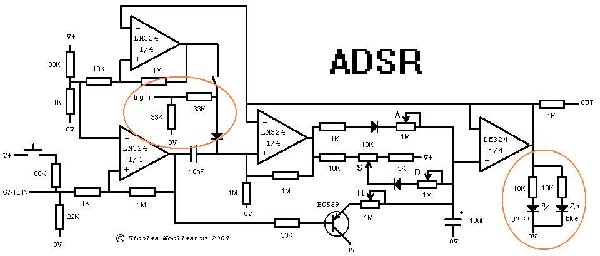
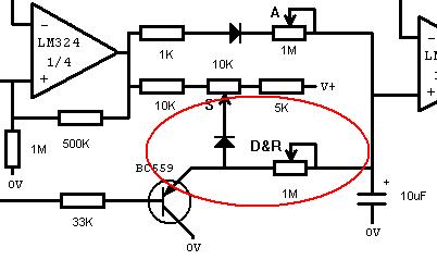
nicolas, i wonder what the blue LED is for? i would have added a NPN and resistor as LED driver...
_________________
cheers,
matthias
____________
Big Boss at fonitronik
Tech Buddy at Random*Source |
|
|
Back to top
|
|
|
numbertalk
Joined: May 05, 2008
Posts: 992
Location: Austin, TX
Audio files: 5
|
| Posted: Thu Feb 19, 2009 10:22 am Post subject:
|
|
|
Thanks!
| fonik wrote: | | numbertalk wrote: | | Would you be willing to post your ready-to-etch PCB image online with a BOM (if that's okay with Nicolas as well)? |
sure. |
|
|
|
Back to top
|
|
|
fonik
Joined: Jun 07, 2006
Posts: 3950
Location: Germany
Audio files: 23
|
| Posted: Thu Feb 19, 2009 4:16 pm Post subject:
|
|
|
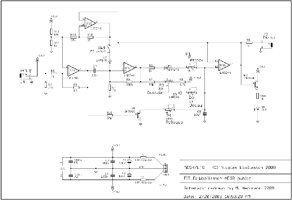
tonight i breadboarded the circuit and powered it with +/-15VA. that's what i came up with:
i lowered the 33ka resistor in the voltage divider at the neg in of the first OpAmp (comparator) to 10k. this gave me a trigger threshold of approx. 1.5V. 
i lowered the 1M resistor in the feedbackpath of the 3rd OpAmp (junction 10nF, diode, 1M to GND...) to 390k, just because this was what i had on hand. it gave me a peak of approx. 9V.
i added a NPN and a 1k resistor as driver for a LED (Collector to +V, Base to output of last OpAmp, Emitter to 1K to LED to GND). 
a 500ka pot for release gave me a better control.
i normalled the input socket to a 10k/10k voltage divider to allow the LFO mode to work.
i found the LFO mode a little bit strange: sustain pot has to be fully ccw. when release pot is fully ccw the LFO would be gateble, which is very cool. 
as soon as the release pot is not ccw the LFO is always on. as soon as i turned up the sustain potentiometer the LFO stopped. 
i did not get the external retrigger input to work. 
experiences, insights or explanations anyone?
_________________
cheers,
matthias
____________
Big Boss at fonitronik
Tech Buddy at Random*Source |
|
|
Back to top
|
|
|
nicolas3141
Joined: May 25, 2007
Posts: 185
Location: Christchurch, New Zealand
|
| Posted: Thu Feb 19, 2009 4:20 pm Post subject:
|
|
|
| widdly wrote: | | I'm not getting much joy from it. The release seems to work as an attack and release and it needs a lot of voltage to trigger. I'd be interested if I've made a mistake in my layout or if I need to modify for this voltage. |
Sounds like a problem with the transistor. Check the soldering, etc around that area and check that you have a PNP transistor with collector to ground and emitter to the release pot and base to the opamp via resistor.
Cheers,
Nicolas |
|
|
Back to top
|
|
|
nicolas3141
Joined: May 25, 2007
Posts: 185
Location: Christchurch, New Zealand
|
| Posted: Thu Feb 19, 2009 4:26 pm Post subject:
|
|
|
| fonik wrote: | | nicolas, i wonder what the blue LED is for? i would have added a NPN and resistor as LED driver... |
My idea with running both green and blue LEDs was that the green would turn on at a lower voltage and the blue at a higher voltage. Could also be done with multiple green leds by adding diodes or zeners in series with some, but not others. To create a kind of crude bargraph type display. Probably a silly idea, but might be fun.
Cheers,
Nicolas |
|
|
Back to top
|
|
|
nicolas3141
Joined: May 25, 2007
Posts: 185
Location: Christchurch, New Zealand
|
| Posted: Thu Feb 19, 2009 4:46 pm Post subject:
|
|
|
| fonik wrote: |
i found the LFO mode a little bit strange: sustain pot has to be fully ccw. when release pot is fully ccw the LFO would be gateble, which is very cool.
as soon as the release pot is not ccw the LFO is always on. as soon as i turned up the sustain potentiometer the LFO stopped.
|
Wow matthias, you got that up and running quickly - for someone with lots of other projects on the go. The weather must be wintry where you are Thank you for feeding back your findings so clearly.
Yes the LFO mode is a little strange, but in a fun kind of way. It continues to surprise me as to when it will do what. That is why I must get around to adding an LED to mine to help me keep track of what it is up to.
As you found the LFO behaves fairly normally if you turn the sustain and release right down and then control the up-ramp and down-ramp of the LFO with the attack and decay pots. Like this I think the gate input will stop the LFO when it is high and let it run when low.
If you turn up the sustain and release pots the LFO will not run, but I think it will if the gate is high. And then the down-ramp is mostly controlled by the release rather than the decay pot.
By raising the trigger voltage on the gate input you have also raised he voltage at which the LFO retriggers. So on your one the LFO will be oscillating between 1.5V and 9V. Not a bad thing at all, just a bit different to mine. You could always use two separate voltage dividers for these two functions.
Cheers,
Nicolas |
|
|
Back to top
|
|
|
fonik
Joined: Jun 07, 2006
Posts: 3950
Location: Germany
Audio files: 23
|
| Posted: Fri Feb 20, 2009 12:41 am Post subject:
|
|
|
| nicolas3141 wrote: | | Wow matthias, you got that up and running quickly - for someone with lots of other projects on the go. The weather must be wintry where you are Thank you for feeding back your findings so clearly. |
indeed. you WANT to stay at home, right beside the oven...
| Quote: | | Yes the LFO mode is a little strange, but in a fun kind of way. It continues to surprise me as to when it will do what. |
agreed. and i thought about adding some additional labeling to the front panel, i.e. "gated LFO" to the CCW position of the release pot?!
| Quote: | | By raising the trigger voltage on the gate input you have also raised he voltage at which the LFO retriggers. So on your one the LFO will be oscillating between 1.5V and 9V. Not a bad thing at all, just a bit different to mine. You could always use two separate voltage dividers for these two functions. |
great idea. i will think about it. a 3pole switch could control the LFO mod, voltage divider and even a cap on the output to remove the offset and center the LFO around GND...
EDIT: cap is bad idea. we are talking about DC voltages here, but should i add an additional DualOpAmp for this action?
(EDIT: corrected schematic uploaded)
| Description: |
| that's what i had on the breadboard yesterday. |
|
| Filesize: |
51.32 KB |
| Viewed: |
2745 Time(s) |
| This image has been reduced to fit the page. Click on it to enlarge. |
|
_________________
cheers,
matthias
____________
Big Boss at fonitronik
Tech Buddy at Random*Source
Last edited by fonik on Fri Feb 20, 2009 3:01 am; edited 2 times in total |
|
|
Back to top
|
|
|
yusynth

Joined: Nov 24, 2005
Posts: 1314
Location: France
|
| Posted: Fri Feb 20, 2009 2:46 am Post subject:
|
|
|
Hi Matthias
I reckon Q2 is there to drive a LED, isn't it ?
_________________
Yves |
|
|
Back to top
|
|
|
fonik
Joined: Jun 07, 2006
Posts: 3950
Location: Germany
Audio files: 23
|
| Posted: Fri Feb 20, 2009 2:49 am Post subject:
|
|
|
| yusynth wrote: | Hi Matthias
I reckon Q2 is there to drive a LED, isn't it ? |
true - but where is the LED? 
(EDIT: corrected schematic uploaded - thank you, yves)
_________________
cheers,
matthias
____________
Big Boss at fonitronik
Tech Buddy at Random*Source |
|
|
Back to top
|
|
|
nicolas3141
Joined: May 25, 2007
Posts: 185
Location: Christchurch, New Zealand
|
| Posted: Fri Feb 20, 2009 3:15 am Post subject:
|
|
|
A hot soldering iron will help keep you warm
I don't think a more complex switch would add much. If you wanted to be able to mess about with the DC offset you could, as you suggest, follow this with a DC mixer like Ken Stone's CGS04 - using the invertable inputs would be best. My philosophy is to have lots of very simple modules so I would rather keep the mixer separate in my setup, but everyone has their own approach to this sort of thing.
Cheers,
Nicolas |
|
|
Back to top
|
|
|
yusynth
Joined: Nov 24, 2005
Posts: 1314
Location: France
|
| Posted: Fri Feb 20, 2009 3:27 am Post subject:
|
|
|
Another point is that it would be more accurate to use a FET-OPA for U1D. Therefore I'd suggest to replace the LM324 by a TL074.
_________________
Yves |
|
|
Back to top
|
|
|
nicolas3141
Joined: May 25, 2007
Posts: 185
Location: Christchurch, New Zealand
|
|
|
Back to top
|
|
|
nicolas3141
Joined: May 25, 2007
Posts: 185
Location: Christchurch, New Zealand
|
| Posted: Fri Feb 20, 2009 3:46 am Post subject:
|
|
|
| Thanks for uploading the redrawn schematic matthias, it makes it so much easier to discuss when we have a drawing with refdeses. I must do better drawings myself. |
|
|
Back to top
|
|
|
fonik
Joined: Jun 07, 2006
Posts: 3950
Location: Germany
Audio files: 23
|
| Posted: Fri Feb 20, 2009 4:51 am Post subject:
|
|
|
| nicolas3141 wrote: | | I don't think a more complex switch would add much. If you wanted to be able to mess about with the DC offset you could, as you suggest, follow this with a DC mixer like Ken Stone's CGS04 - using the invertable inputs would be best. My philosophy is to have lots of very simple modules so I would rather keep the mixer separate in my setup, but everyone has their own approach to this sort of thing. |
actually this is my point of view, too. for such jobs i use one of my voltage processor, i.e. my Attenuverting Mixer.
| Quote: | | Thanks for uploading the redrawn schematic matthias, it makes it so much easier to discuss when we have a drawing with refdeses. I must do better drawings myself. |
hey, your drawing is actually much better than mine. better readability, neat and clear. i just have to do it in eagle for the PCB layouts...
_________________
cheers,
matthias
____________
Big Boss at fonitronik
Tech Buddy at Random*Source |
|
|
Back to top
|
|
|
fluxmonkey
Joined: Jun 24, 2005
Posts: 708
Location: cleve
|
| Posted: Fri Feb 20, 2009 7:46 am Post subject:
|
|
|
| frijitz wrote: | This is fantastic. Why isn't everyone jumping up and down about it?
Ian |
i'm with Ian, thanks very much for posting this. but even more fantastic, IMHO, is watching the collaborative creation process as folks start testing an refining the initial idea. we've seen it here before wit things like the Klee, it is really inspiring. very grateful to be a small part of this community.
any chance of modifying that stripboard layout with the new improvements?
b
_________________
www.fluxmonkey.com |
|
|
Back to top
|
|
|
nicolas3141
Joined: May 25, 2007
Posts: 185
Location: Christchurch, New Zealand
|
| Posted: Fri Feb 20, 2009 2:25 pm Post subject:
|
|
|
| bbob wrote: | | any chance of modifying that stripboard layout with the new improvements? |
So far, nothing really significant has changed, just the values of a couple of resistors, plus an LED has been added which you would probably want on the front panel rather than the stripboard anyway If you're building this with the stripboard layout above you will need to follow the schematic to find out what is missing - because all the missing stuff is hanging off the back of the front panel pots, sockets, switches. I know some people consider this type of construction terribly messy, but its currently my preferred way of doing it because its quick and easy (for small simple modules anyway) and also easy to continue modifying.
Cheers,
Nicolas |
|
|
Back to top
|
|
|
nicolas3141
Joined: May 25, 2007
Posts: 185
Location: Christchurch, New Zealand
|
|
|
Back to top
|
|
|
|

 Forum index » DIY Hardware and Software