Joined: Apr 19, 2010 Posts: 346 Location: San Francisco, CA
Audio files: 13
Posted: Tue Jul 17, 2012 12:49 pm Post subject:
tiego wrote:
it does work , from either point of D1; ( works the same from the amount pot mid point still I am looking for a point where to get the ENV signal after the release control stage but before the amount stage...
(meaning I can use the env full level externally without cranking the amount inside the SOST)
I don't think such a point exists. The Amount pot is practically where the signal enters the circuit.
Also, regarding "either side of D1", yes the signal will be mostly the same, but the diode is there for reverse voltage protection. I assume if you add an out and accidentally plug the wrong thing in there you could damage your envelope circuitry. _________________ -Jim
Posted: Wed Feb 20, 2019 6:47 am Post subject:
envelope follower
I don't know how many SOST have been built over the years. I just finished building one and I found that the ENV- follower was not working properly. It was more like a comparator with no threshold.
According to LTSpice changing R61 from 1K to 100K makes it much better. Will check that in the module soon. _________________
cheers,
matthias
____________
Big Boss at fonitronik
Tech Buddy at Random*Source
R61 must be changed from 1K to 100K to make the envelope follower work properly. With 1K it works more or less like a comparator, holding the inverting input of the OpAmp at almost 0V.
Accordingly one has to change R5 from 470K to 100K to have a decent impact onthe modulation. _________________
cheers,
matthias
____________
Big Boss at fonitronik
Tech Buddy at Random*Source
do you run your SOST on 12V or 15V? I built the SOST for my 5U / 15V system, and I always thought the ENV works fine, but I will check again. Maybe you could run Spice sim. with 15V as well?
do you run your SOST on 12V or 15V? I built the SOST for my 5U / 15V system, and I always thought the ENV works fine, but I will check again. Maybe you could run Spice sim. with 15V as well?
Cheers
Lars
I run on 12V, but that does actually not make any difference.
With just 1K to GND on the inverting input the opamp works as a comparator. the result is a kind of sloped gate, which of course has an effect in the end. but it is not an envelope follower and it will shoot as soon as you turn the ENV knob away from CCW.
This is also what I got from this single and only useful demo on youtube, where a guitar player demoes it. And he states almost exactly that.
This or I got something terribly wrong in general, which I do not believe at this point.
BTW you could compare the envelope follower in the SOST with the envelope follower in the MS20 and you will quickly spot it. _________________
cheers,
matthias
____________
Big Boss at fonitronik
Tech Buddy at Random*Source
I will try changing the resistors tomorrow and make a before/after comparison.
So theoretically ...if I put e.g. a sequencer line into the SOST and vary the input level, the flanging sweep then should also vary a lot more than before. With the old resitor values it stays more or less static. Is that correct?
(too bad I have my MS20 in the studio and not near the modular/workbench..)
theoretically yes. however, the settings are a little bit fiddly and as you can hear in my video above, the effect is more noticable with slow changes.
with the old values i actually had the input audio modulating the flanger since the comparator switched at every zero crossing (at audio rate!). _________________
cheers,
matthias
____________
Big Boss at fonitronik
Tech Buddy at Random*Source
I changed both R61 and R5 and now the ENV Mod potentiometer is way more useful than before. It now feels like a modulation amount knob like it should be, before it was kind of the same sound over the whole knob range.
And you're also right: it is a bit more fiddly to use envelope modulation on the SOST (or any flanger?) than on some filter. Doesn't sound "right" on every signal.
Just compared the schematics of SoST-Flanger with the original StormTideFlanger - Jürgen used the same Envelopefollower back then. So he made the same mistake twice?
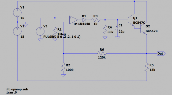
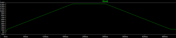
Made a short simulation too. I'm not shure, if I coult trust LTSpice, as it says 140Volts on output, by +/-15V as power supply...
env-follower.png
Description:
Scematic of my simulation, with the corrected resistor
Filesize:
19.51 KB
Viewed:
651 Time(s)
This image has been reduced to fit the page. Click on it to enlarge.
env-fol-sim.png
Description:
Sim of the original schematic
Filesize:
7.28 KB
Viewed:
651 Time(s)
This image has been reduced to fit the page. Click on it to enlarge.
Ooops... missed a dot in the values for V3. 5Volts input is a bit too much But with 0.5V input LTSpice runs still to 24V output... _________________ ...ich will doch nur löten...
It obviously is a mistake. The R61 (R2 in your simulation) has to be in the 100K ballpark, not just 1K. _________________
cheers,
matthias
____________
Big Boss at fonitronik
Tech Buddy at Random*Source
Posted: Mon Mar 22, 2021 5:37 am Post subject:
50/100Hz hum problem
Hi! I build the SOST flanger and it sounds pretty fantastic. Some small debugging here and there but getting there. I do have one bigger problem I don't know how to solve. I have a 50/100 Hz hum.
The hum is always there (whenever the effect is on). But it get's stronger when the signal gets stronger. Here's a little audio example (https://www.dropbox.com/s/1tpejxf6muxz0ue/SOST%2050%3A100%20Hz%20problem.wav?dl=0). You hear it reacting to the volume.
Ok Problem solved. My walmart adapter wasn't supplying enough juice.. Fixed it.
One last thing (in case anybody reads this..)
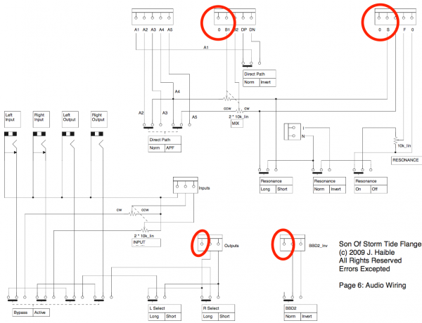
On the Audio Connections schematic I see these open connections (mostly connected to ground I think.. SEE ATTACHMENT What do I do with these? Nothing? And if yes.. Why are they there.. I currently leave them empty and everything seems to work.. But just wanna double check..
Thanks
Screen Shot 2021-04-03 at 15.31.03.png
Description:
Filesize:
131.6 KB
Viewed:
189 Time(s)
This image has been reduced to fit the page. Click on it to enlarge.
Done!
At least almost.. I'm getting some weird noise when the BBD2 switch is on "normal"mode. I made little recording. Just a simple sine wave into the flanger. I'm witching it from normal to inv. Pretty obvious.. Does anybody know what this could be.
In the recording I hear clicks .. that probably is the mode switching, and then in one of the two modes there is some distortion ... or actually on better listening it seems to be there in both modes, just a bit softer in one mode ..
Does this also happen when you use a lower input signal? It sounds a bit like it could be clipping somewhere? _________________ Jan
also .. could someone please turn down the thermostat a bit.
In the recording I hear clicks .. that probably is the mode switching, and then in one of the two modes there is some distortion ... or actually on better listening it seems to be there in both modes, just a bit softer in one mode ..
Does this also happen when you use a lower input signal? It sounds a bit like it could be clipping somewhere?
Yes it's me switching. It's not so much the distortion (clipping). But that obvious "sizzle electrical noise" sound that comes in and out.. It has nothing to do with input volume it seems.
Hmm I probably need to dive into the schematic whenever I have time (WHY DID NOBODY TELL ME DIY IS SOOO TIME CONSUMING:-)).. Maybe it's an IC?
You cannot post new topics in this forum You cannot reply to topics in this forum You cannot edit your posts in this forum You cannot delete your posts in this forum You cannot vote in polls in this forum You cannot attach files in this forum You can download files in this forum

 Forum index » DIY Hardware and Software » Jürgen Haible designs