| Author |
Message |
Ayab
Joined: Oct 27, 2015
Posts: 186
Location: London, UK
|
 Posted: Sun Jan 03, 2016 7:47 am Post subject: Posted: Sun Jan 03, 2016 7:47 am Post subject:
Subject description: Karplus Strong Project |
  |
|
CreatorLes
Best wishes for a healthy and happy 2016 (and to all on Electro-Music).
Thank you for your work on such an interesting and creative project. I would really like to experiment with this synthesis method. Do you have any pcb's available or are you planning another run?
I would also be interested in the 'brick'
All the best
Ben |
|
|
Back to top
|
|
 |
CreatorLes
Joined: Oct 05, 2014
Posts: 84
Location: San Antonio TX USA
|
| Posted: Thu Jan 14, 2016 3:18 pm Post subject:
|
|
|
I've been out of the loop so long i forgot.
Les |
|
|
Back to top
|
|
|
masterofstuff124

Joined: Sep 21, 2015
Posts: 23
Location: Miami, Florida
|
| Posted: Mon Jun 20, 2016 7:58 am Post subject:
|
|
|
| pcbs? or the most up to date files so i can get the some boards made? |
|
|
Back to top
|
|
|
masterofstuff124
Joined: Sep 21, 2015
Posts: 23
Location: Miami, Florida
|
| Posted: Tue Jul 26, 2016 9:27 pm Post subject:
|
|
|
alright built one of these up. any one have any idea what the correct values of r27 and r32 are for 12v power supply? any other necessary changes?
my FBk knob and VCF knob both dont seem to do all that much.
I replaced both r11- 40.2k and r18 49.9k with 47k. and C7 with 2.7n
only 2 2k tempcos for the tranny pairs? I also flipped both of the 2n3906's backwards as mentioned earlier in the thread.
Should I bring all the labelled points on the board to jacks? sum, vol,jls etc...
should feedback send be normalled to fdbk jack? i.e. connected to its switch lug? with attenuator?
different styles of triggers seem to drastically change the tone which is neat!
anyone have any switching ideas for the different kinds of chips?
any other switching ideas. like infinite feedback, or changing out the tone caps in the loops etc...
Lots of questions. I know. really keen on this circuit!@ my first vco so my knowledge is lacking. |
|
|
Back to top
|
|
|
AlanP
Joined: Mar 11, 2014
Posts: 746
Location: New Zealand
Audio files: 41
|
| Posted: Tue Apr 04, 2017 10:13 pm Post subject:
|
|
|
Les's Karplus-Strong circuit sounds really, really good!

I had a good fiddle with it today, and the Stim input is vital to getting good sounds out of this circuit. I tried a saw wave into the Stim input, and was getting rather insane sounds, so I googled "karplus-strong synthesis".
Noise is what needs stimulating. Modulated noise. The longer the envelope, the more "breathy" and panpipe-y it sounds.

This is what I worked up from Les's excellent schematic. Didn't have to do any patches due to stupidity on my own part, so that's always a plus. Hopefully Les doesn't mind my putting his name on the front, or E-M!
Thanks for making this circuit public, Les. |
|
|
Back to top
|
|
|
BlacKcaT
Joined: Dec 08, 2016
Posts: 26
Location: Italy
Audio files: 1
|
| Posted: Wed Apr 05, 2017 4:16 am Post subject:
|
|
|
 nice! nice!
I'm wondering if are still there some pcb to buy... |
|
|
Back to top
|
|
|
masterofstuff124
Joined: Sep 21, 2015
Posts: 23
Location: Miami, Florida
|
| Posted: Wed Apr 05, 2017 7:11 am Post subject:
|
|
|
AlanP you need to start selling all your pcb/panel designs. everytime I see one I immediately want it....
i want this....
|
|
|
Back to top
|
|
|
BlacKcaT
Joined: Dec 08, 2016
Posts: 26
Location: Italy
Audio files: 1
|
| Posted: Wed Apr 05, 2017 8:10 am Post subject:
|
|
|
| masterofstuff124 wrote: | AlanP you need to start selling all your pcb/panel designs. everytime I see one I immediately want it....
i want this....
|
this is herorack addiction ! |
|
|
Back to top
|
|
|
Inventor
Stream Operator

Joined: Oct 13, 2007
Posts: 6221
Location: near Austin, Tx, USA
Audio files: 267
|
| Posted: Thu Apr 06, 2017 1:18 am Post subject:
|
|
|
Oh man, I just found this - I feel so joyful to have my name on your version of the KS! This really made my day, and the PCB looks rock solid primo grade A extra fine!
I gotta stress that this was a community project and lots of people helped. Without that help I never could have done it! I even quit it just before it was complete and folks pitched in to carry it to fruition.
Now if you can fabricate it and breathe new life into the project, well, nothing would make me feel better than that (well not much!). Enjoy to the max.
Les
p.s. I'll pay for two built boards with panels if I can afford it, would love to set up a "brick" again as it made IMHO the best sounds I ever made at em.
_________________
"Let's make noise for peace." - Kijjaz |
|
|
Back to top
|
|
|
mosc
Site Admin

Joined: Jan 31, 2003
Posts: 18308
Location: Durham, NC
Audio files: 235
G2 patch files: 60
|
| Posted: Thu Apr 06, 2017 1:04 pm Post subject:
|
|
|
Congrats, Alan. I'm almost as happy as Les on this. Putting electro-music.com on your front panel is great too. Splendid work. Got any recordings of this module?
_________________
--Howard
my music and other stuff |
|
|
Back to top
|
|
|
YashN

Joined: Jun 27, 2011
Posts: 104
Location: Canada
|
| Posted: Fri Apr 07, 2017 6:53 am Post subject:
|
|
|
Looks so neat, well done Alan & Les and others.
How's the faceplate labelling done? |
|
|
Back to top
|
|
|
Skrog Productions

Joined: Jan 07, 2009
Posts: 1226
Location: Scottish Borders
Audio files: 161
|
|
|
Back to top
|
|
|
AlanP
Joined: Mar 11, 2014
Posts: 746
Location: New Zealand
Audio files: 41
|
| Posted: Mon Apr 24, 2017 12:23 am Post subject:
|
|
|
A quick mess-around shows that this can also be used as a flanger (at least, with the 3207 BBD I currently have in it.)
Signal into Stim, LFO into VCO CV. Turn Feedback to minimum first. Freq is now Manual, VCO CV Level is Depth. Once you've got a good flange-y thing, try adding a bit of feedback. |
|
|
Back to top
|
|
|
AlanP
Joined: Mar 11, 2014
Posts: 746
Location: New Zealand
Audio files: 41
|
| Posted: Fri Sep 15, 2017 6:55 pm Post subject:
|
|
|
Did some very quick ear-testing with some modern BBD reproductions from Smallbear, with this circuit.
The Bei-Ling BL3207 sounds very good in this, not much noise, good range with the Freq knob to get a relatively wide range response.
The Coolaudio v3208, on the other hand, sounds dreadful. Noisy. The lowest frequency is higher than the BL3207, and the highest frequency is lower. I have some Coolaudio v3205d chips lying around but, with how noisy they are in a Memory Man clone I have, and how noisy the v3208 was, I decided not to bother perfing up an adaptor board.
I have a suspicion that this has something to do with the relative simplicity of this circuit -- no compander is used, relatively light filtering, meaning that lower quality BBDs don't quite cut it. The good thing is that Smallbear has the Bei Ling chip in decent quantities. |
|
|
Back to top
|
|
|
chaffel3
Joined: Jul 05, 2017
Posts: 4
Location: Philadelphia
|
| Posted: Fri May 31, 2019 10:54 pm Post subject:
|
|
|
| I ordered pcbs and parts for the KS11, way cheaper than I thought! Big thanks to Les for making an awesome DIY project! |
|
|
Back to top
|
|
|
chaffel3
Joined: Jul 05, 2017
Posts: 4
Location: Philadelphia
|
| Posted: Wed Jun 19, 2019 7:37 pm Post subject:
|
|
|
I'm getting really close to finishing a build but I'm not able to adjust VCO frequency and the filter isn't having any effect.
I'm building it into a eurorack module so I'm using +- 12 volts on the supply, what resistor are people using for r27 and r32? I think the original 14.3k is for 9 volts if I'm not mistaken. I installed trimmers but haven't had any luck experimenting.
What am I looking for in terms of observable behavior when I have r27 and r32set right? (I have an O scope if that's helpful)
One big hint is that the TL074 is getting pretty warm so I'm looking around that for clues how to proceed.
Thanks all! |
|
|
Back to top
|
|
|
AlanP
Joined: Mar 11, 2014
Posts: 746
Location: New Zealand
Audio files: 41
|
| Posted: Wed Jun 19, 2019 8:41 pm Post subject:
|
|
|
If an opamp is warming up like that, then you've got a short somewhere, or a wrong value component.
If you have an o'scope, then put a continuous waveform into the Stim input, and trace through the circuit until you find where it stops being passed on. My guess would be that it will be somewhere in the opamp that is heating up. (The bias for the BBD in this circuit is ultra-simple, so it should be fine.)
I just used the stock resistor values for my 12V build. |
|
|
Back to top
|
|
|
chaffel3
Joined: Jul 05, 2017
Posts: 4
Location: Philadelphia
|
| Posted: Sun Jun 30, 2019 5:48 pm Post subject:
|
|
|
I've decided to start a new build on a fresh pcb so I can verify it at every step, I also am now using a variable power supply so I can give it +-9. I just re-read the whole thread and flipped my Q2 transistor around, now trying to nail down resistor values.
I have a scope on the TP5 test point (OCV) which is the output of the op amp that feeds to the transistors. The range I'm seeing adjusting the frequency knob is -0.15 to 0.2 volts. From someone earlier in the thread their range was 0.167V to -0.163V which sounds similar enough, might be able to figure out how to make it symmetrical around 0 volts.
At test point 16 (OCC) which is the point right after the transistor stage I'm seeing a range of about -7.9 to 0 by adjusting the freq knob. The trimmer has a minor effect around the middle of the range but minimum and maximum are unaffected. Someone else posted that they had -4.32V to -8.13V. At about 6 oclock way the voltage is near 0 and the rest of the rotation of the freq pot doesn't have any effect.
I had a wrong resistor value messing up my level shifter but I fixed that and I have a decent clock coming out of the level shifter, it could be a more even pulse width but it seems fine.
I'm going to build the rest of board #2 and see if my op amp overheating happens again, this time I'm more prepared to diagnose.
I have learned a lot so far it's been fun! |
|
|
Back to top
|
|
|
chaffel3
Joined: Jul 05, 2017
Posts: 4
Location: Philadelphia
|
| Posted: Fri Jul 05, 2019 4:29 pm Post subject:
|
|
|
I got my second build working and I'm super excited! Works well at +-9V and +-12, calibration is the last thing I need to do. I have another couple PCBs and I'm planning on building them eventually. Maybe I'll do 3 to make a power chord polyphonic set someone mentioned in the thread.
Now that I have a known working board I can retest the voltages on my first one. I'm finding a mysterious voltage of VDD on two of my op amp pins (1 and 2) which should be near zero, which must explain the overheating I am encountering. I have the op amp unplugged from the board so it should have any significant voltage. It is somehow related a current path through the 100 ohm pot so I'll be investigating all those paths to VDD.
I have basically memorized the schematic at this point. I feel like I have learned a lot about CV input and 13700 Oscillators which has really given me confidence in planning some of my own designs in the future! |
|
|
Back to top
|
|
|
mosc
Site Admin
Joined: Jan 31, 2003
Posts: 18308
Location: Durham, NC
Audio files: 235
G2 patch files: 60
|
| Posted: Tue Jul 30, 2019 4:56 pm Post subject:
|
|
|
| chaffel3 wrote: | | ... I feel like I have learned a lot about CV input and 13700 Oscillators which has really given me confidence in planning some of my own designs in the future! |
This makes me feel great, and I’m sure Les feels the same. This is one of the reasons we started electro-music.com some 16 years ago. We support, encourage, inspire, and appreciate each other. (Other things too.)
Congrats on getting things working.
_________________
--Howard
my music and other stuff |
|
|
Back to top
|
|
|
Inventor
Stream Operator
Joined: Oct 13, 2007
Posts: 6221
Location: near Austin, Tx, USA
Audio files: 267
|
| Posted: Fri Aug 02, 2019 10:24 am Post subject:
|
|
|
Aw... Warm fuzzies and cool breezies all around!
Les
_________________
"Let's make noise for peace." - Kijjaz |
|
|
Back to top
|
|
|
jean bender
Joined: Feb 21, 2010
Posts: 139
Location: france
|
| Posted: Sun Nov 15, 2020 6:53 am Post subject:
|
|
|
Ok, so 10 years after, i'm finding back my pcbs used for a specific project.. Wow, it's been a while.
I'd like to rebuild my units, but i can't find back the documentation i used by the past.
Inventor's website seems to be dead, and i remember i used it helping me building my karplus..
Anybody would have any idea how to find back this site ?
Or would somedbody help me tuning the several trimpots used ?
Thanks a lot !!
_________________
http://h.a.k.free.fr/
www.electroncanon.org |
|
|
Back to top
|
|
|
Grumble

Joined: Nov 23, 2015
Posts: 1320
Location: Netherlands
Audio files: 30
|
| Posted: Sun Nov 15, 2020 2:13 pm Post subject:
|
|
|
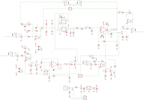
This is what I have
| Description: |
|
| Filesize: |
421.5 KB |
| Viewed: |
305 Time(s) |
| This image has been reduced to fit the page. Click on it to enlarge. |
|
| Description: |
|

Download (listen) |
| Filename: |
ks jack.pdf |
| Filesize: |
26.31 KB |
| Downloaded: |
282 Time(s) |
| Description: |
|
Download (listen) |
| Filename: |
ks v0.2 eng.pdf |
| Filesize: |
27.57 KB |
| Downloaded: |
727 Time(s) |
_________________
my synth |
|
|
Back to top
|
|
|
jean bender
Joined: Feb 21, 2010
Posts: 139
Location: france
|
| Posted: Mon Nov 16, 2020 1:10 pm Post subject:
|
|
|
Hi !
Thanks for you repply !
But sadly my boards don't seem to be the same batches. I have two trimmers on it, and can't find back how to calibrate them...
So sad to not have grab inventor's website.. i know that's not cool, but it seems there are so many down diy websites actually..
I will try to post some pictures from my boards.
Best
J.
_________________
http://h.a.k.free.fr/
www.electroncanon.org |
|
|
Back to top
|
|
|
Grumble
Joined: Nov 23, 2015
Posts: 1320
Location: Netherlands
Audio files: 30
|
| Posted: Mon Nov 16, 2020 3:10 pm Post subject:
|
|
|
Maybe you can find the website you are looking for in the wayback machine?
https://archive.org/web/
_________________
my synth |
|
|
Back to top
|
|
|
|

 Forum index » DIY Hardware and Software » Les Hall's Projects including eChucK


