Posted: Mon Oct 26, 2009 7:01 am Post subject:
Help with stripboard layout... Subject description: TR808 clones
I found a couple of TR808 clones online, these have been made for perfboard, which I find awkward to use (I prefer stripboard). I wondered if anyone here who is good at stripboarding might be able to do a stripboard layout of these great circuits?
808 Bass 808 Snare 808 Hihat _________________
I too found those clones. I made up a perfboard last week of the kick drum but had no luck getting it to work.
Since then I have breadboarded it up and have it working in a fashion... only by probing around with the (+) a bit. Having trouble triggering it with a SPST switch to (+) as Eric suggests. I have been emailing Eric about this project and he has been very approachable and helpful. I had the value of C12 and C13 wrong for a while...
I am awaiting a response from Eric about this trigger problem I'm having.
Have you breadboarded this? Or perfboarded it up? When I get this functional I will be drawing up and testing a stripboard version. I shall post the drawing here...hopefully soon!
Really want this 808 BD! When I get it working I shall move onto the other two modules and stripboard them too. Sorry I cant be of more help at present...
Joined: Nov 18, 2007 Posts: 301 Location: England
Audio files: 11
G2 patch files: 1
Posted: Sun Nov 22, 2009 8:51 am Post subject:
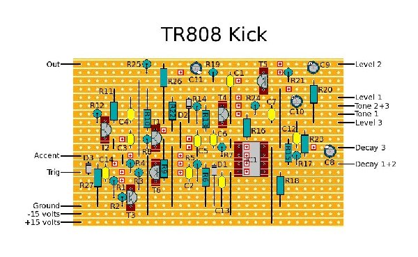
Here's a stripboard layout for the Kick drum.
The component numbering follows the schematic you linked to.
I'd check the pinout for the transistors and don't just put them in how they look on the layout, they might not match. Note that T5 is upside down with its emitter at the top, where as the other NPN transistors all have their emitter at the bottom.
The IC goes with pin 1 top left.
I've double checked the layout but I haven't built it so there may be errors.
tr808-kick.jpg
Description:
Now updated to correct R18 and R19 error
Filesize:
139.66 KB
Viewed:
3285 Time(s)
This image has been reduced to fit the page. Click on it to enlarge.
Last edited by slacker on Mon Nov 23, 2009 10:33 am; edited 1 time in total
Posted: Sun Nov 22, 2009 9:20 pm Post subject:
Subject description: TR808 Kick BOM
Many thanks to everyone's responses here. This certainly looks like a really nice project to build. I think I'm going to guinea pig it this week and I'll post back to let you all know how I get on.
I'm wondering if there are any interesting mods that can be done here to extend the decay, change envelope curve etc?
(A 1V/oct pitch CV would be really amazing)!
Anyway, without further ado, here is the BOM. I took this info from the names/values pages of the documentation, so please double check this!
*No indication of whether these are lin or log, although on the paperwork, it says "(guess)" next to the level control, so I'm assuming it's a case of trial and error? Maybe someone can help out here
Lektroid... Here is a response I received from Eric regarding C12 and C13:
C14 is 0.1u ceramic, same type as C12 and C13.
>
> C3 and C7 are 100n = 0.1u. its the same value but for
> some reason I say 100n for polyester caps and 0.1u for
> ceramic. anyhow, you could use ceramic or polyester for
> any of them. I'm just picky and use poly for audio
> path and ceramic for utility stuff.
>
>
> indeed C3, C7, C12, C13, C14 are all 0.1uF
>
I have used these blue Monolithic Multilayer Ceramics for these caps. Seems to work ok. However, I still can't get this thing to trigger with a SPST as Eric suggests. Any ideas anyone?
Also, slacker.... Have you built this stripboard yet? Just wondering if it is verified. And can it be triggered manually? If so how?
I have used 10k A's for the level and tone pots. Not sure if this is correct but it seems to work...
Slacker... I think R18 and R19 need to be swapped on your stripboard layout. Should R18 read R19 and vice versa, or am I wrong... ?
Maybe easier if I swap them in the BOM... I need to edit that post anyway
-minus- wrote:
Lektroid... Here is a response I received from Eric regarding C12 and C13:
C14 is 0.1u ceramic, same type as C12 and C13.
>
> C3 and C7 are 100n = 0.1u. its the same value but for
> some reason I say 100n for polyester caps and 0.1u for
> ceramic. anyhow, you could use ceramic or polyester for
> any of them. I'm just picky and use poly for audio
> path and ceramic for utility stuff.
>
>
> indeed C3, C7, C12, C13, C14 are all 0.1uF
I have edited the BOM accordingly
Quote:
I have used these blue Monolithic Multilayer Ceramics for these caps. Seems to work ok. However, I still can't get this thing to trigger with a SPST as Eric suggests. Any ideas anyone?
Maybe easier to use a Gate -> Trigger circuit (I'm almost certain I've seen one on this forum somewhere), I know triggered units can be very fussy and need that exact pulse to work. I had trouble with a DR55 rimshot clone, I ended up using my DR110 trigger out to run it. _________________
ah you see... this is where I'm out of my depth. I have a lot to learn! Been doing this for less than a year. I love this kick sound! Really need to get it to work! I appreciate the comments LektroiD. Yet to find a trigger... still trying to understand how they work! More research to do.
ah you see... this is where I'm out of my depth. I have a lot to learn! Been doing this for less than a year. I love this kick sound! Really need to get it to work! I appreciate the comments LektroiD. Yet to find a trigger... still trying to understand how they work! More research to do.
If you want a quick solution, grab yourself a Boss DR110 analogue drum machine from ebay. It's a hidden gem; sounds like a TR606 with a TR808 clap. It also has a trigger out on it. Another drum machine around the same value with a trigger out on is the TR626, although that uses digital samples. Either way, it's a solution to your trigger dilema. _________________
I want to build all my sounds myself. I'm not actually into drum rhythms as such. Love noise. Bit of an old fart from the industrial era! eg Throbbing Gristle, Coil, Nurse with Wound etc... But I'm getting a bit off topic now....
Joined: Nov 18, 2007 Posts: 301 Location: England
Audio files: 11
G2 patch files: 1
Posted: Mon Nov 23, 2009 10:31 am Post subject:
-minus- wrote:
Slacker... I think R18 and R19 need to be swapped on your stripboard layout. Should R18 read R19 and vice versa, or am I wrong... ?
Yes you're right R18 and R19 are wrong, the numbering on the schematic was quite difficult to read. I've corrected the layout and reposted it.
When I get time I'll add the BOM to the layout, just wanted to post it so people could have a look over it.
I'm half way through building this.. Due to shortages, I had a look at the 1N914A datasheet for substitutes; the same datasheet also covers 4148 diodes. I'm wondering if it would be ok to use 4148's for all the diodes, or must I specifically use the 1N914A for D3?
In my local electronic chain store catalogue (Dick Smith Electronics, Australia), the 1N4148/914 are listed as one of the same thing. I have been curious if this is why my breadboard and perf board haven't triggered with the switch Eric suggests on his site. I've been wondering about this diode... but maybe there are other reasons for it not working for me?
I'd be interested if you have any success with your build in terms of triggering it manually. I've found other ways of getting it to fire on various locations around the board. Found a few interesting 'bends' too! Nice to get it to work correctly though....
I'm due a component delivery tomorrow, so I'll finish building mine then and let you know how I get on. Did you use a 914A, or a 4148 for your trigger circuit?
I'd be interested to know what bends you've found too! _________________
The 914 and the 4148 are both just small signal diodes. I haven't found a situation yet where you can't substitute one for the other. That would not be the problem.
I'd love to breadboard this and see how to get the trigger to work, but I'm getting the "lab" cleaned up now and can't afford the distraction. Maybe later. _________________ What makes a space ours, is what we put there, and what we do there.
Joined: May 16, 2005 Posts: 8933 Location: Birmingham, England, UK
Audio files: 11
G2 patch files: 1
Posted: Thu Nov 26, 2009 7:19 am Post subject:
Uncle Krunkus wrote:
I'd love to breadboard this
Howabout stripboard it Mista K?? _________________ ACHTUNG!
ALLES TURISTEN UND NONTEKNISCHEN LOOKENPEEPERS!
DAS KOMPUTERMASCHINE IST NICHT FÜR DER GEFINGERPOKEN UND MITTENGRABEN! ODERWISE IST EASY TO SCHNAPPEN DER SPRINGENWERK, BLOWENFUSEN UND POPPENCORKEN MIT SPITZENSPARKSEN.
IST NICHT FÜR GEWERKEN BEI DUMMKOPFEN. DER RUBBERNECKEN SIGHTSEEREN KEEPEN DAS COTTONPICKEN HÄNDER IN DAS POCKETS MUSS.
ZO RELAXEN UND WATSCHEN DER BLINKENLICHTEN.
Joined: May 16, 2005 Posts: 8933 Location: Birmingham, England, UK
Audio files: 11
G2 patch files: 1
Posted: Thu Nov 26, 2009 11:54 am Post subject:
I've got the excellent Korg EM-1. These circuits would be the icing on the cake. I too could be James Stinson!! _________________ ACHTUNG!
ALLES TURISTEN UND NONTEKNISCHEN LOOKENPEEPERS!
DAS KOMPUTERMASCHINE IST NICHT FÜR DER GEFINGERPOKEN UND MITTENGRABEN! ODERWISE IST EASY TO SCHNAPPEN DER SPRINGENWERK, BLOWENFUSEN UND POPPENCORKEN MIT SPITZENSPARKSEN.
IST NICHT FÜR GEWERKEN BEI DUMMKOPFEN. DER RUBBERNECKEN SIGHTSEEREN KEEPEN DAS COTTONPICKEN HÄNDER IN DAS POCKETS MUSS.
ZO RELAXEN UND WATSCHEN DER BLINKENLICHTEN.
Joined: May 16, 2005 Posts: 8933 Location: Birmingham, England, UK
Audio files: 11
G2 patch files: 1
Posted: Thu Nov 26, 2009 11:58 am Post subject:
_________________ ACHTUNG!
ALLES TURISTEN UND NONTEKNISCHEN LOOKENPEEPERS!
DAS KOMPUTERMASCHINE IST NICHT FÜR DER GEFINGERPOKEN UND MITTENGRABEN! ODERWISE IST EASY TO SCHNAPPEN DER SPRINGENWERK, BLOWENFUSEN UND POPPENCORKEN MIT SPITZENSPARKSEN.
IST NICHT FÜR GEWERKEN BEI DUMMKOPFEN. DER RUBBERNECKEN SIGHTSEEREN KEEPEN DAS COTTONPICKEN HÄNDER IN DAS POCKETS MUSS.
ZO RELAXEN UND WATSCHEN DER BLINKENLICHTEN.
Joined: May 16, 2005 Posts: 8933 Location: Birmingham, England, UK
Audio files: 11
G2 patch files: 1
Posted: Thu Nov 26, 2009 3:00 pm Post subject:
Uncle Krunkus wrote:
v-un-v wrote:
Uncle Krunkus wrote:
I'd love to breadboard this
Howabout stripboard it Mista K??
There you go planting seeds again Tom!
If I had time to scratch myself, it would be a pleasure.
"All good things come to those who wait", as they say! _________________ ACHTUNG!
ALLES TURISTEN UND NONTEKNISCHEN LOOKENPEEPERS!
DAS KOMPUTERMASCHINE IST NICHT FÜR DER GEFINGERPOKEN UND MITTENGRABEN! ODERWISE IST EASY TO SCHNAPPEN DER SPRINGENWERK, BLOWENFUSEN UND POPPENCORKEN MIT SPITZENSPARKSEN.
IST NICHT FÜR GEWERKEN BEI DUMMKOPFEN. DER RUBBERNECKEN SIGHTSEEREN KEEPEN DAS COTTONPICKEN HÄNDER IN DAS POCKETS MUSS.
ZO RELAXEN UND WATSCHEN DER BLINKENLICHTEN.
I'm due a component delivery tomorrow, so I'll finish building mine then and let you know how I get on. Did you use a 914A, or a 4148 for your trigger circuit?
I'd be interested to know what bends you've found too!
Changing the DECAY pot to a 1M seems to hold the decay forever when fully dialed. I've probed around the circuit a bit with a piece of wire without any detrimental results... I hope! I put another pot (500K) between the left leg of R18 and the right leg of R23 and by turning it, it makes the kick drum sound like toms.
Still no luck at all with the triggering though! I have found a few ways of getting a sound out of it. One is to connect the ACCENT to (+), then take a wire from (+) and probe around the circuit a bit until it fires! Try (+) to pin 3 of the IC... or (+) to pin 5 for a kind of kick which rings out in various lengths.... or (+) to pin 6 for a real wobbly decay. Not for the purists I admit, but for those desperado's out there (like myself), it's an option.
At the moment to trigger it repeatedly, I have a simple circuit breadboarded up next to the 808 kick breadboard. It consists of a 9V battery, two transistors (548 and 558), a resistor, a 500K pot and a cap... This produces a steady CLICK noise when put through an amp. I've tried to use this to trigger the kick the 'proper' way, but no joy. I'm triggering the kick (if you can call it that), by running the (-) output of this smaller board, to (+) on the kick. The (+) of the smaller board is working in various places on the 808 breadboard... (see above paragraph)
(+) to R10 or R11 has some strange results if I remember correctly. Tie the accent to (+) and run a wire from (+) touching various spots around the circuit and see what you come up with.
I tried the Forrest Mims PULSE GENERATOR in the Engineer's Mini-Notebook 555 Timer IC Circuits to trigger this too, but no luck....
Hope those diodes have arrived LektroiD! Let us know how you get on...
Otherwise we'll simply have to wait for the Stripboard Jedi, Krunkus to sort out his lab and save us...
You cannot post new topics in this forum You cannot reply to topics in this forum You cannot edit your posts in this forum You cannot delete your posts in this forum You cannot vote in polls in this forum You cannot attach files in this forum You can download files in this forum

 Forum index » DIY Hardware and Software » The layout factory