| Author |
Message |
LektroiD

Joined: Aug 23, 2008
Posts: 1019
Location: Scottish Borders
Audio files: 2
G2 patch files: 2
|
 Posted: Sun Jan 10, 2010 11:17 pm Post subject:
Soundlab Ultimate - Build diary & difficulties Posted: Sun Jan 10, 2010 11:17 pm Post subject:
Soundlab Ultimate - Build diary & difficulties
Subject description: Mission Accomplished! |
  |
|
What equivalents are available for the 9.1V Zener (1N5239B)?
Many thanks in advance
**UPDATE**
The Ultimate is now built and complete (nearly - awaiting banana socket order).
A video:
http://www.youtube.com/watch?v=wyp9bQeYL3U&fmt=18
Some Pictures:
| Description: |
|
| Filesize: |
251.43 KB |
| Viewed: |
264 Time(s) |
| This image has been reduced to fit the page. Click on it to enlarge. |

|
| Description: |
|
| Filesize: |
146.92 KB |
| Viewed: |
244 Time(s) |
| This image has been reduced to fit the page. Click on it to enlarge. |

|
| Description: |
|
| Filesize: |
150.4 KB |
| Viewed: |
252 Time(s) |
| This image has been reduced to fit the page. Click on it to enlarge. |

|
_________________
LektroiD
Last edited by LektroiD on Mon Apr 26, 2010 10:20 pm; edited 2 times in total |
|
|
Back to top
|
|
 |
LektroiD
Joined: Aug 23, 2008
Posts: 1019
Location: Scottish Borders
Audio files: 2
G2 patch files: 2
|
| Posted: Wed Jan 13, 2010 3:39 am Post subject:
|
|
|
No reply... I guess I'm stuffed on the diode then? 
Maybe someone can tell me the implications of;
a) leaving it out?
b) bridging it with wire?
c) using any old 9v1 zener?
Next question; in the list it mentions a 'low leakage capacitor' (C60, 0.01µF), I searched Rapid Electronics (where I'm getting the obscure resistors from), but returns no results. What exactly is a 'low leakage capacitor'? I've not heard of one. Would someone be kind enough to direct me to a Rapid part number?
_________________
LektroiD |
|
|
Back to top
|
|
|
mtec
Joined: Nov 07, 2009
Posts: 30
Location: Snowy Mountions, Australia
|
|
|
Back to top
|
|
|
Skrog Productions

Joined: Jan 07, 2009
Posts: 1224
Location: Scottish Borders
Audio files: 160
|
| Posted: Wed Jan 13, 2010 9:39 am Post subject:
Re: Soundlab Ultimate - Diode query.. |
|
|
| LektroiD wrote: | What equivalents are available for the 9.1V Zener (1N5239B)?
Many thanks in advance |
Just read your post...... I have a bag of 50 9V1 zeners and i could spare you a few if needed .
Capacitor ... polystyrene or silver mica have best carachteristics , expensive compared to polypropylene.
Dave in Galashiels, doon the A7 road. |
|
|
Back to top
|
|
|
LektroiD
Joined: Aug 23, 2008
Posts: 1019
Location: Scottish Borders
Audio files: 2
G2 patch files: 2
|
| Posted: Thu Jan 14, 2010 12:42 am Post subject:
|
|
|
Hi Dave, and thanks for the tips. I have some zeners here, I was really wondering if I could substitute the 1N5239B with one of the following:
BZX61 C9V1
BZX79 C9V1
BZY88 C9V1
..If so, which would be best?
Or am I better off sourcing a 1N5239B?
Incidentally, did you manage to source any PN4391 transistors for this?
_________________
LektroiD |
|
|
Back to top
|
|
|
LektroiD
Joined: Aug 23, 2008
Posts: 1019
Location: Scottish Borders
Audio files: 2
G2 patch files: 2
|
| Posted: Sun Jan 17, 2010 9:14 pm Post subject:
|
|
|
anyone?
_________________
LektroiD |
|
|
Back to top
|
|
|
magman
Joined: Feb 04, 2009
Posts: 363
Location: Liverpool, UK
|
| Posted: Wed Jan 20, 2010 4:56 am Post subject:
|
|
|
Lektroid,
I believe the key factor in choosing the right equivalent is the power dissipation, not the voltage. The 1N5238B is a 500mW device, so I expect that the BZX79 is the closest match, but the BZX61 would also work.
To be honest, the power dissipation in this circuit is so low, I suspect they would all work fine. As long as they give the 9.1V reference the circuit needs, you could just pick the one that fits best on the board.
Regards
Magman |
|
|
Back to top
|
|
|
Uncle Krunkus
Moderator

Joined: Jul 11, 2005
Posts: 4761
Location: Sydney, Australia
Audio files: 52
G2 patch files: 1
|
| Posted: Wed Jan 20, 2010 2:35 pm Post subject:
|
|
|
Yeah,
I'd tend to say, "Any 9V1 zener would do just fine."
PS, sorry I didn't see this earlier. 
_________________
What makes a space ours, is what we put there, and what we do there. |
|
|
Back to top
|
|
|
Thalassa

Joined: Jan 27, 2006
Posts: 95
Location: Spain
Audio files: 5
|
|
|
Back to top
|
|
|
LektroiD
Joined: Aug 23, 2008
Posts: 1019
Location: Scottish Borders
Audio files: 2
G2 patch files: 2
|
| Posted: Sun Jan 24, 2010 4:35 am Post subject:
|
|
|
Thanks guys, I'll use a BZX79 in its place.
_________________
LektroiD |
|
|
Back to top
|
|
|
LektroiD
Joined: Aug 23, 2008
Posts: 1019
Location: Scottish Borders
Audio files: 2
G2 patch files: 2
|
| Posted: Wed Feb 03, 2010 9:27 am Post subject:
|
|
|
I managed to source some of the correct diodes, so that is in place now..
A few more queries:
- C7, C17 & C29 are listed as .005µF Polycarbonate or Polystyrene. However, the closest I could source were 5100pF (5N1). Are these ok?
http://uk.farnell.com/lcr-components/fscex-5100pf-1-160v/capacitor-5-1nf-160v/dp/9520570?Ntt=952-0570
- R254 & R267 are listed as 3MΩ. I can only find 3.3MΩ or 2.7MΩ. Can I use either of these in place, or is there another way (kludging 3x 1MΩ together in series, for example)?
- On the PSU, the electrolytic capacitors are 3300µF @35V, I cannot source these anywhere, can I use any other value?
- Should I use thermal paste on the tempcos?
Many thanks in advance 
_________________
LektroiD |
|
|
Back to top
|
|
|
magman
Joined: Feb 04, 2009
Posts: 363
Location: Liverpool, UK
|
| Posted: Thu Feb 04, 2010 1:16 am Post subject:
|
|
|
Lektroid,
I suspect you would be OK with that variation in the cap size for C7 etc. as its only a 2% difference and polycarbonate caps are normally 5% tolerance (and the design doesn't even specify a tolerance).
If you want to hunt down the precise value, here's a good link for a supplier of polystyrene caps that you could try:
http://www.rush-on-line.co.uk/cap_forums.html#458
For R254 &267, these are both fed from a pot, so I doubt you have anything to worry about in terms of the tolerance. You could try a 3M3 and if the range of the LFO Rate pot isn't what you expect when the synth is operating, try a lower value, but I doubt this will be a problem.
Not sure what the problem is with finding the PSU caps, as there are loads of different 3300uF 35V caps available on the Farnell site (though they aren't particularly cheap). If you want to try some alternates though, you can safely use a higher value - say 4700uF 35V - or a higher voltage - say 3300uF 50V - as long as the lead pitch is the same (7.5mm pitch) for fitting them into the Wallwart PSU PCB.
More capacitance in the PSU smoothing caps will just improve the regulation of the PSU (the PSU's capacity to respond to demands for current without dropping the supply voltage). An increase in voltage on a cap often leads to a larger cap, but in terms of how the circuit works you can always use a higher voltage rating for a cap, never a lower voltage (unless you are looking to generate some Magic Smoke).
I always use thermal paste with Tempco's and it won't do any harm.
Regards
Magman |
|
|
Back to top
|
|
|
LektroiD
Joined: Aug 23, 2008
Posts: 1019
Location: Scottish Borders
Audio files: 2
G2 patch files: 2
|
| Posted: Sat Feb 06, 2010 5:41 am Post subject:
|
|
|
Many thanks for your reply, Magman. Much appreciated. I've got on and done the above. All except I haven't yet installed my 5n1 polystyrene capacitors into C7, C17 & C29, as I'm concerned it may affect the scaling. The link you provided looks great, however the postage makes 3 caps very expensive, so I'll wait until I can order a bulk amount (I'll have to go through my other unfinished projects).
I do have one more query though; the trimmers.. Which way round do these go? My trimmers are marked with pins 1, 2 & 3, yet there is no marking on the board. I'd like to install them all so clockwise increases said values etc.
Also, I'm assuming a bi-polar electrolytic capacitor, is the same as non-polarised?
Again, many thanks.
_________________
LektroiD |
|
|
Back to top
|
|
|
jordroid
Joined: Jan 17, 2010
Posts: 193
Location: ithaca, new york
|
| Posted: Sat Feb 06, 2010 8:07 am Post subject:
|
|
|
The trimmers are just a tiny little weird looking potentiometer, some of them even have a little design molded into the side that shows their function- a resistor with its ends being pins one and three, and a wiper connected to pin two. I would clip a meter probe on the middle pin (the wiper) and read the resistance to the outer pins while adjusting the trimmer until it makes sense, i try to do that with any part i don't understand well if it's meterable.
What magman was saying about the tolerance is that even if you buy three 0.005 caps they could very easily be as far or farther off target than the ones you already have, and most people wouldn't sweat it.
Bi-polar and non-polar caps are the same.
If it was me i would throw those caps in there pronto because i would be crazy impatient to see how it sounds, but your deliberation is commendable. |
|
|
Back to top
|
|
|
LektroiD
Joined: Aug 23, 2008
Posts: 1019
Location: Scottish Borders
Audio files: 2
G2 patch files: 2
|
| Posted: Sat Feb 06, 2010 12:13 pm Post subject:
|
|
|
| jordroid wrote: | | The trimmers are just a tiny little weird looking potentiometer, some of them even have a little design molded into the side that shows their function- a resistor with its ends being pins one and three, and a wiper connected to pin two. I would clip a meter probe on the middle pin (the wiper) and read the resistance to the outer pins while adjusting the trimmer until it makes sense, i try to do that with any part i don't understand well if it's meterable. |
I know this. As I said, I can see the pinout order on the component, but nothing is marked on the PCB.
_________________
LektroiD |
|
|
Back to top
|
|
|
jordroid
Joined: Jan 17, 2010
Posts: 193
Location: ithaca, new york
|
| Posted: Sat Feb 06, 2010 2:19 pm Post subject:
|
|
|
Ah, sorry i wasn't quite clear enough. What i meant was that once one has the trimmer sussed out you can figure out how to get what you want by comparing it to the VCO schematic. The schematic also does have pin numbers for all the trimmers.
regards |
|
|
Back to top
|
|
|
LektroiD
Joined: Aug 23, 2008
Posts: 1019
Location: Scottish Borders
Audio files: 2
G2 patch files: 2
|
|
|
Back to top
|
|
|
magman
Joined: Feb 04, 2009
Posts: 363
Location: Liverpool, UK
|
| Posted: Sun Feb 07, 2010 11:10 pm Post subject:
|
|
|
LektroiD,
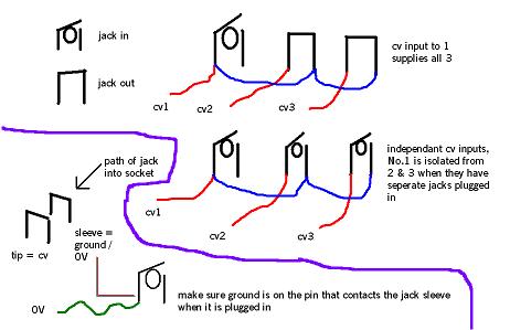
If you use switched rather than un-switched jacks for the VCO2 and VCO3 CV inputs, you can do away with the extra switch.
You can then connect the input from VCO1 CV to the normalled connection of the CV inputs for VCO2 and VCO3, these will then use the VCO1 CV until you plug something into the relevant jack.
I hope that explanation is clear enough (though reading it again it assumes you know what a normalled connection is).
Regards
Magman |
|
|
Back to top
|
|
|
LektroiD
Joined: Aug 23, 2008
Posts: 1019
Location: Scottish Borders
Audio files: 2
G2 patch files: 2
|
| Posted: Mon Feb 08, 2010 8:02 am Post subject:
|
|
|
Magman, that sounds like a much better way! I only have one switched jack in my collection, so if I can get away with wiring up just using one switched and the other jacks non-switched, I'll do that. Either way, I think I'll need a diagram.
_________________
LektroiD |
|
|
Back to top
|
|
|
Skrog Productions
Joined: Jan 07, 2009
Posts: 1224
Location: Scottish Borders
Audio files: 160
|
| Posted: Mon Feb 08, 2010 10:39 am Post subject:
|
|
|
sorry for jumping in magman ,i couldn't resist a dog rough sketch....
| Description: |
|
| Filesize: |
22.54 KB |
| Viewed: |
14952 Time(s) |
|
| Description: |
|
| Filesize: |
47.54 KB |
| Viewed: |
236 Time(s) |
| This image has been reduced to fit the page. Click on it to enlarge. |

|
| Description: |
|
| Filesize: |
68.56 KB |
| Viewed: |
227 Time(s) |
| This image has been reduced to fit the page. Click on it to enlarge. |
|
|
|
|
Back to top
|
|
|
Skrog Productions
Joined: Jan 07, 2009
Posts: 1224
Location: Scottish Borders
Audio files: 160
|
| Posted: Mon Feb 08, 2010 10:50 am Post subject:
|
|
|
| hope that sketch is not too confusing, if you are using the synth for bass lines & leads etc you'll likley have the 3 osc's all tuned together so you'll only use jack 1 / cv1 with 2 & 3 commoned to that . |
|
|
Back to top
|
|
|
LektroiD
Joined: Aug 23, 2008
Posts: 1019
Location: Scottish Borders
Audio files: 2
G2 patch files: 2
|
| Posted: Mon Feb 08, 2010 11:27 am Post subject:
|
|
|
Superb! Thanks Skrog & Magman, all is clear now 
_________________
LektroiD |
|
|
Back to top
|
|
|
ashleym
Joined: Aug 20, 2009
Posts: 181
Location: uk
|
| Posted: Tue Feb 09, 2010 3:07 pm Post subject:
|
|
|
Come on hurry up!!!! I am ordering in the PCBs in a couple of weeks and I am finding all this a good warm up but I am not enjoying the wait.....
Have you ordered the front panels from Music From Outer Space? I am using this wait time to design (well, make a very similar version but in blue) a panel from Shaeffer. My thoughts are if I am making it myself it might a well look the way I want it to.
I am also ordering the expander board, are you looking at this?
I will read your posts at greater length at work tomorrow and see if there is anything I can add.
Good luck. |
|
|
Back to top
|
|
|
LektroiD
Joined: Aug 23, 2008
Posts: 1019
Location: Scottish Borders
Audio files: 2
G2 patch files: 2
|
| Posted: Wed Feb 10, 2010 7:59 pm Post subject:
|
|
|
Just had a thought whilst browsing the schematics.. On the VCO's, can the waveform selector switch be substituted with a potentiometer? If so, what would be the optimal value to work optimally?
For example, it would need to close off the opposing waveform completely without any leakage. I'm sure mixing a little bit of the alternate waveform in would yield much more interesting results than just fixed square or saw.
_________________
LektroiD |
|
|
Back to top
|
|
|
LektroiD
Joined: Aug 23, 2008
Posts: 1019
Location: Scottish Borders
Audio files: 2
G2 patch files: 2
|
| Posted: Sun Feb 14, 2010 11:35 pm Post subject:
|
|
|
Further to my last reply; I wonder if the attenuators can be used to achieve the same result (in > Square / out > Saw)?
Can someone please confirm (I've been waiting patiently for a reply before wiring this section).
many thanks in advance
_________________
LektroiD |
|
|
Back to top
|
|
|
|

 Forum index » DIY Hardware and Software » MusicFromOuterSpace.com designs by Ray Wilson

