| Author |
Message |
BananaPlug

Joined: Jul 04, 2007
Posts: 307
Location: Philly
Audio files: 5
|
 Posted: Thu Aug 05, 2010 2:25 pm Post subject: Posted: Thu Aug 05, 2010 2:25 pm Post subject:
|
  |
|
| macumbista wrote: | | TekniK wrote: | | nice wiring,i like the use of those flat cables |
I've used both flat wiring and wrapped wires in my builds (see the last front/back photo of the multiplier I posted a few days ago for the wrapped wire version). I noticed particularly on an 8x8 matrix mixer I built that parallel flat cables tend to give a lot more cross-talk between the channels. Am I alone in this discovery? |
What to do in any given situation depends on a lot of things but sometimes people make every other wire of the flat cable be ground. That's sort of like having a half shielded cable. You also have to consider capacitance between adjacent wires in the cable. I sometimes peel off a three wire strip of ribbon cable to go from PCB to a pot but for the various ins and outs I think separate wires arranged to not run tight together is the best. Bundling looks nice but also provides the proximity crosstalk requires. |
|
|
Back to top
|
|
 |
emdot_ambient
Joined: Nov 22, 2009
Posts: 667
Location: Frederick, MD
|
| Posted: Tue Aug 10, 2010 3:35 pm Post subject:
|
|
|
Not very sexy, but without a power supply the sexy stuff can't happen. Here's my first completed module:


 |
|
|
Back to top
|
|
|
sduck

Joined: Dec 16, 2007
Posts: 459
Location: Nashville
Audio files: 5
|
| Posted: Tue Aug 10, 2010 4:37 pm Post subject:
|
|
|
Here's my Jurgen Haible Son of Storm Tide Flanger -
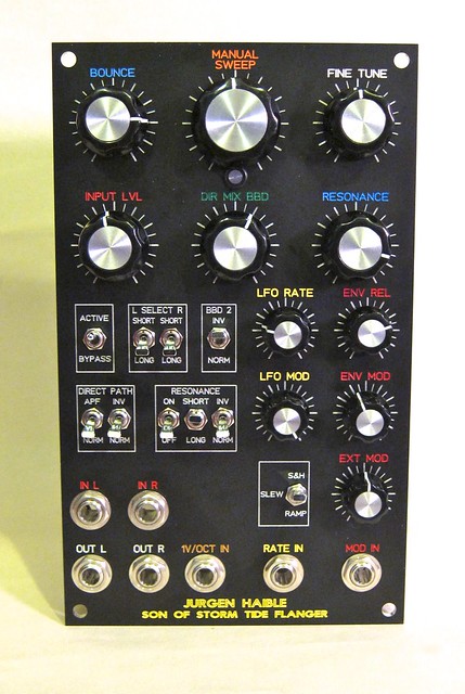
The layout of the front panel isn't the greatest - but everything's there at least.
The construction of this threw me a few problems. First, I ordered the wrong kind of resistors - those big fat ones are cute and cheap but don't really fit well. I was able to substitute a bunch of them with normal sized ones I had on hand, but still had to use a lot of the big ones. Also, I didn't really have the right size bracket, so used 2 smaller ones instead, and then cut them a bit too small for the components, so I ended up angling the pcb to make it all fit. Doesn't look great, but it works.
Oh - it's an excellent sounding flanger, and I haven't even calibrated it yet! |
|
|
Back to top
|
|
|
adambee7
Joined: Apr 04, 2009
Posts: 420
Location: united kingdom
|
| Posted: Tue Aug 10, 2010 7:54 pm Post subject:
|
|
|
very nice sduck. Your system must be getting quite big now.  |
|
|
Back to top
|
|
|
macumbista

Joined: Sep 12, 2007
Posts: 398
Location: berlin
Audio files: 3
|
| Posted: Wed Aug 11, 2010 8:45 am Post subject:
|
|
|
| BananaPlug wrote: | | What to do in any given situation depends on a lot of things but sometimes people make every other wire of the flat cable be ground. That's sort of like having a half shielded cable. |
That's a good idea, I'll have to try that!
_________________
Esoteric drones and nonlinear distortion
Custom/handmade experimental instruments
macumbista.net |
|
|
Back to top
|
|
|
sduck
Joined: Dec 16, 2007
Posts: 459
Location: Nashville
Audio files: 5
|
| Posted: Wed Aug 11, 2010 6:01 pm Post subject:
|
|
|
| adambee7 wrote: | | very nice sduck. Your system must be getting quite big now. |
Naw, it's teeny tiny -

Actually, I've ran out of space and have to juggle modules. So far it's been fairly easy - rotate out the ones that aren't working right until I fix them. |
|
|
Back to top
|
|
|
raberaucht
Joined: Apr 18, 2010
Posts: 5
Location: Cologne, Germany
|
| Posted: Sat Aug 14, 2010 10:33 am Post subject:
|
|
|
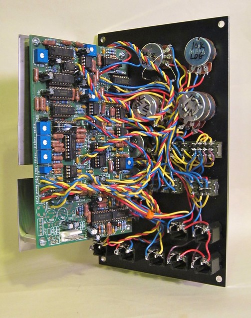
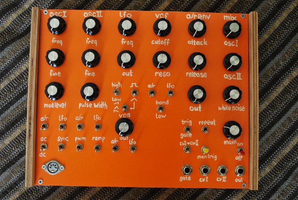
So - here's mine! My first synth DIY build...
It's a MFOS Sound Lab Mini with fine tune and osc2 -> osc1 modulation mods plus a midimplant.
The space besides the VCA is for an additional sample & hold - not sure yet if I'll need it though.
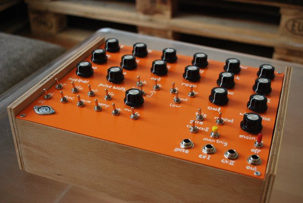
I spray painted the panel myself and as you can tell by the looks I did also the writing...
The design was inspired by Mr. Braskas visit at Tigric's lab.
This was great fun! Looking forward to build some more...
Thank you for this great and inspiring forum!
Best,
raberaucht
| Description: |
|
| Filesize: |
672.47 KB |
| Viewed: |
339 Time(s) |
| This image has been reduced to fit the page. Click on it to enlarge. |
|
| Description: |
|
| Filesize: |
658.61 KB |
| Viewed: |
323 Time(s) |
| This image has been reduced to fit the page. Click on it to enlarge. |
|
|
|
|
Back to top
|
|
|
TekniK

Joined: Aug 10, 2008
Posts: 1059
|
| Posted: Sat Aug 14, 2010 2:37 pm Post subject:
|
|
|
| that orange color is very sweet and the knobs are perfect on it |
|
|
Back to top
|
|
|
LetterBeacon
Joined: Mar 18, 2008
Posts: 454
Location: London, UK
|
| Posted: Sat Aug 14, 2010 6:00 pm Post subject:
|
|
|
| Looking good! How's the Midimplant working out? |
|
|
Back to top
|
|
|
raberaucht
Joined: Apr 18, 2010
Posts: 5
Location: Cologne, Germany
|
| Posted: Sun Aug 15, 2010 2:49 am Post subject:
|
|
|
Thanks!
The Midimplant is working perfect so far.
It is really small and quite easy to set up.
I'm using just one CV and one gate output out of the two - all I need for the Soundlab.
To drive both OSCs with the same control voltage from the Midimplant I simply connected the CVI and CVII jacks with the switch besides the manual trigger that says 'CVI -> CVII'. |
|
|
Back to top
|
|
|
kkissinger
Stream Operator

Joined: Mar 28, 2006
Posts: 1436
Location: Kansas City, Mo USA
Audio files: 45
|
| Posted: Mon Aug 16, 2010 8:46 am Post subject:
|
|
|
| raberaucht wrote: | So - here's mine! My first synth DIY build...
It's a MFOS Sound Lab Mini with fine tune and osc2 -> osc1 modulation mods plus a midimplant. |
Congratulations on a successful DIY build.
Ambitious for a first project -- well done.
_________________
-- Kevin
http://kevinkissinger.com |
|
|
Back to top
|
|
|
sndbyte
Joined: Jun 26, 2009
Posts: 119
Location: sf
|
| Posted: Mon Aug 16, 2010 10:46 pm Post subject:
|
|
|
I just finished building the Soundlab Plus. I posted more detailed photos of the build in the MFOS section. Here is the finished piece:
 |
|
|
Back to top
|
|
|
TekniK
Joined: Aug 10, 2008
Posts: 1059
|
| Posted: Tue Aug 17, 2010 12:39 am Post subject:
|
|
|
| very cute |
|
|
Back to top
|
|
|
fonik

Joined: Jun 07, 2006
Posts: 3950
Location: Germany
Audio files: 23
|
| Posted: Tue Aug 17, 2010 11:35 am Post subject:
|
|
|
amazing woodwork, especially for the speaker/amp
_________________

cheers,
matthias
____________
Big Boss at fonitronik
Tech Buddy at Random*Source |
|
|
Back to top
|
|
|
kkissinger
Stream Operator
Joined: Mar 28, 2006
Posts: 1436
Location: Kansas City, Mo USA
Audio files: 45
|
|
|
Back to top
|
|
|
Danno Gee Ray
Joined: Sep 25, 2005
Posts: 1351
Location: Telford, PA USA
|
| Posted: Sat Aug 21, 2010 6:50 pm Post subject:
|
|
|
| Most awesome system Kevin! |
|
|
Back to top
|
|
|
TekniK
Joined: Aug 10, 2008
Posts: 1059
|
| Posted: Sun Aug 22, 2010 1:28 am Post subject:
|
|
|
| for sure the most sexy Aries ever. |
|
|
Back to top
|
|
|
LektroiD

Joined: Aug 23, 2008
Posts: 1019
Location: Scottish Borders
Audio files: 2
G2 patch files: 2
|
|
|
Back to top
|
|
|
fonik
Joined: Jun 07, 2006
Posts: 3950
Location: Germany
Audio files: 23
|
| Posted: Wed Sep 01, 2010 7:12 am Post subject:
|
|
|
| LektroiD wrote: | Nothing special, but it all makes some fancy noises when I need them..
Need to build a cabinet for them now |
c'mon... it IS special. you've built it on your own. it's nothing off the shelf. and i like this retro look with the raw panels and the davis(?) knobs.
- and the soundlab looks georgeous! noce color scheme...
_________________
cheers,
matthias
____________
Big Boss at fonitronik
Tech Buddy at Random*Source |
|
|
Back to top
|
|
|
richardc64

Joined: Jun 01, 2006
Posts: 679
Location: NYC
Audio files: 26
|
| Posted: Thu Sep 02, 2010 6:17 am Post subject:
|
|
|
Wow! I shouldn't have neglected this thread.
| emdot_ambient wrote: | | Not very sexy, but without a power supply the sexy stuff can't happen. |
And just because it isn't sexy doesn't mean it can't look good. (This applies to people, as well.)
sduck
I'm not a fan of color coding but those are nice choices for labeling.
raberaucht
Un-ashamedly home made without looking sloppy. The writing enhances that. Love the Halloween color scheme.
sndbyte
So damn CLEAN!
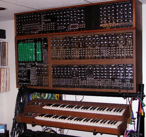
kkissinger
I'm gonna go out on a limb and assume you're very tall. I'd need a step ladder to reach the top unit. Or that's a low ceiling exaggerating the illusion of height
What are all the green illuminated buttons?
| LektroiD wrote: | | Need to build a cabinet for them now |
Pretty good-looking for temporary accommodations.
_________________
Revenge is a dish best served with a fork... to the eye |
|
|
Back to top
|
|
|
kkissinger
Stream Operator
Joined: Mar 28, 2006
Posts: 1436
Location: Kansas City, Mo USA
Audio files: 45
|
| Posted: Thu Sep 02, 2010 7:40 am Post subject:
|
|
|
| richardc64 wrote: | kkissinger
I'm gonna go out on a limb and assume you're very tall. I'd need a step ladder to reach the top unit. Or that's a low ceiling exaggerating the illusion of height
What are all the green illuminated buttons? |
The ceiling is a bit low in my studio however I have to stand to reach the top cabinet. A new keyboard/cabinet stand is on my 'do list'.
Here is a link to a post I made that explains the green buttons:
http://electro-music.com/forum/topic-7183-519.html
I'm bringing this synth with me to EM2010 for a seminar on "DIY modules for analog synthesis" and for a musical set.
_________________
-- Kevin
http://kevinkissinger.com |
|
|
Back to top
|
|
|
hendrixworkshop
Joined: May 06, 2009
Posts: 57
Location: Austin, TX
|
| Posted: Sat Sep 04, 2010 9:53 pm Post subject:
Damn! -- just Pg 15 |
|
|
@emdot_ambient -- That is a great piece of work. Clean, efficient with room to grow... I don't ever decorate any of my enclosures (I haven't done crazy nice stuff like in this thred) and I like it that way. I think of all my instruments/effects as power tools - So if they look like an old cast aluminum belt sander, it makes me happy! As long as they are durable and work. I have used a clear red plastic Hammond enclosure though...
@sduck -- Damn...very well done and labeled. The wiring is tight! It looks very sculptural with the primary colors and the gauge you chose. The colored labeling on front is nice and makes me think of how the instruments on the original Enterprise must have been labeled. Gene R. had a thing for color coding.
@raberaucht -- My dad and I have always had a thing for that color of orange - it is perfect -- We call it the Gulf Oil orange because he had a bunch of cans of that color labeled for Gulf Oil for use at their gas stations! I like the expedient hand lettering. You're the one using the device. I can't think of anything more familiar to the eye, than your own script.
@sndbyte -- Your presentation is impeccable. I love the soundlab cabinet, but especially the custom speaker. The speaker implies (to me at least) a lot of love and instrument husbandry. Did you do the front panel also?
@kkissinger -- Jesus man...Do you have kids?? That is a behemoth. It is like a spaceship of your very own. (like when I was a kid) I wanna come play at your house. The woodworking/joinery is awesome - beautiful mahogany.
@LektroiD -- Nice suitcase setup. I love looking at suitcase instruments - they make me think of secret agents, intelligence agencies, weapons of some sort, that you just show up, open, and throw down with.
I saw this thread in January, and thought " I should post some of my stuff", and here we are at September. I had a busy summer, and built a lot of units - but now the kids started back to school it takes so much more of my time...I have to sneak off to the workshop, saying that I'm cleaning, or some such excuse that will fly with my wife. Here I am at 11:00pm just getting started, and I have at least 2 hours of stuff I want to get done.
Thanks for everyone's posts! |
|
|
Back to top
|
|
|
hendrixworkshop
Joined: May 06, 2009
Posts: 57
Location: Austin, TX
|
| Posted: Sat Sep 04, 2010 10:29 pm Post subject:
Some Gristleizers I built... |
|
|
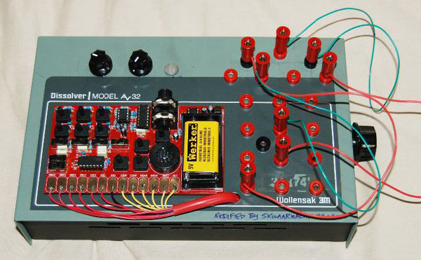
Creds: The Gristleizer. A design based on the circuit by Roy Gwinn and popularized by Chris Carter. Board designed by Taylor Livingston.
The first one (pictured last) is housed in an old BUD Radio box - all steel. This a great effect. Many think a one-trick-pony at first. It depends on how carefully you use it. It can do gentle 15 second long filter sweeps or it can do heavily filtered, choppy tremolo. No labels - but it's just 1 rotary switch and 4 knobs, so at least I can remember.
The second one (first three pics) I was going for thumb control - about the footprint of a playstation controller. Vintage knobs, housed in a cheapy RadioShack project box. Sold to a fellow in Las Vegas for $100. I thought he got a deal, because, as it was a prototype, I put a lot of love in its design and made many tweaks to sound and hardware.
| Description: |
|
| Filesize: |
402.99 KB |
| Viewed: |
171 Time(s) |
| This image has been reduced to fit the page. Click on it to enlarge. |

|
| Description: |
|
| Filesize: |
344.26 KB |
| Viewed: |
192 Time(s) |
| This image has been reduced to fit the page. Click on it to enlarge. |

|
| Description: |
|
| Filesize: |
356.63 KB |
| Viewed: |
190 Time(s) |
| This image has been reduced to fit the page. Click on it to enlarge. |

|
| Description: |
|
| Filesize: |
784.99 KB |
| Viewed: |
182 Time(s) |
| This image has been reduced to fit the page. Click on it to enlarge. |

|
|
|
|
Back to top
|
|
|
hendrixworkshop
Joined: May 06, 2009
Posts: 57
Location: Austin, TX
|
| Posted: Sat Sep 04, 2010 10:34 pm Post subject:
Out of warranty - the bugbrand devices, modded |
|
|
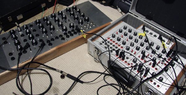
Long winded explanation about a bugbrand BoardWeevil 2009 mod:
Since I've had the bugbrand BoardWeevil, I've wanted to stabilize the touch pads so that I could hold one of those cool in-between sounds (Jetson-sy, babbling water, starve crunchiness, etc.). So I finally took the plunge and made a breakout box for it.
1. This breakout box has a lot of wires in it. When I get finished describing it, you'll probably be horrified. I added an LFO (directly below the Weevil, tapped right off of the positive and negative board origin right under the battery. It has tri and square waves, and a rate and depth control. Hardly need the rate part, because being able to change the waveshape greatly increases the playability. I took the design of Peter's at CasperElectronics - to add an LFO to the pitch contact in a Speak and Spell bend. The two banana jacks immediately to the right of the LFO (blk and red) are the leads from the LFO circuit that went to the pitch control(blk), and the V+(red).
The banana jacks (black) in a C shape just to the right of the BoardWeevil are laid out the same as the touch points on the Weevil, just turned CW 90 degrees. There are also 2 - 12 step rotary switches on the left side of the box - each connects to the same 12 touch points/banana jacks, so you can mix them up and play the switches. The jacks for the switches are the two red ones at the top of the "C". Unfortunately one of the switches feels like it will grind itself apart someday soon. I'm ordering better switches. They are non-shorting rotary switches. I bet your thinking - how much current have I robbed from the circuit? A lot. The starve knobs does not as acutely effect the sound. So I imagine it is always starving a little. The V+ seems to act like a voltage follower(?).
The potentiometer banana jacks are on the top right. They all have switches to turn them off. So you can prepare beforehand and add voices, or subtract them when soloing. The first, from left to right, goes to a photoresistor. The second to a single turn B1k pot. The third and the one diectly under it go to two 10-turn potentiometers. Those are the most gratifying of the breakouts because they can feel out the starved in betweens and hold them - sometimes they sound like they are sweeping a filter. Real nice. The last two pot breakout sections go to the x and Y axis of the analog joystick. The joystick is good for soloing, but it's range of motion (or quality) doesn't have any subtlety. It was the original accessory for the breakout box.
I don't know how I could have condensed this. Sorry
| Description: |
|
| Filesize: |
228.56 KB |
| Viewed: |
194 Time(s) |
| This image has been reduced to fit the page. Click on it to enlarge. |

|
|
|
|
Back to top
|
|
|
hendrixworkshop
Joined: May 06, 2009
Posts: 57
Location: Austin, TX
|
|
|
Back to top
|
|
|
|

 Forum index » DIY Hardware and Software