Holy monkfish!!! This chunks will definitely survive the next world war! _________________ --
How may I be of disservice?
---
Music for conscious listening @ http://www.fmdelight.de/
Joined: Apr 17, 2006 Posts: 2810 Location: New York
Audio files: 24
Posted: Tue Aug 09, 2011 4:05 pm Post subject:
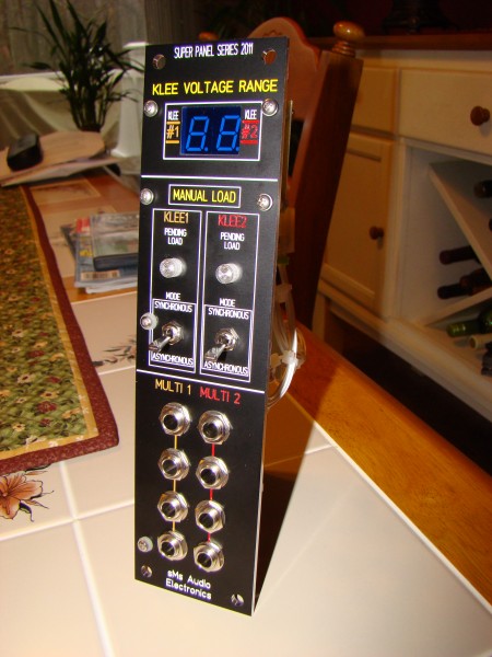
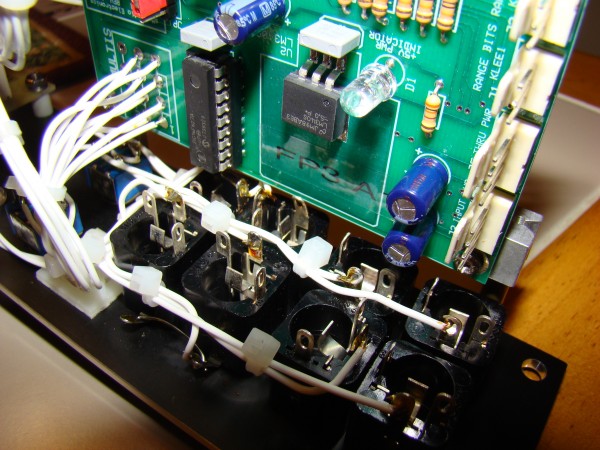
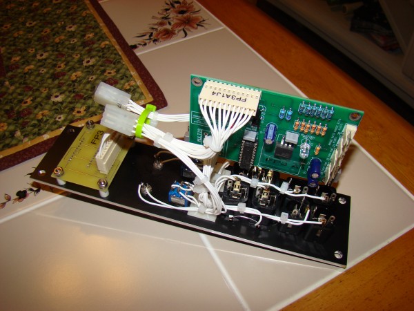
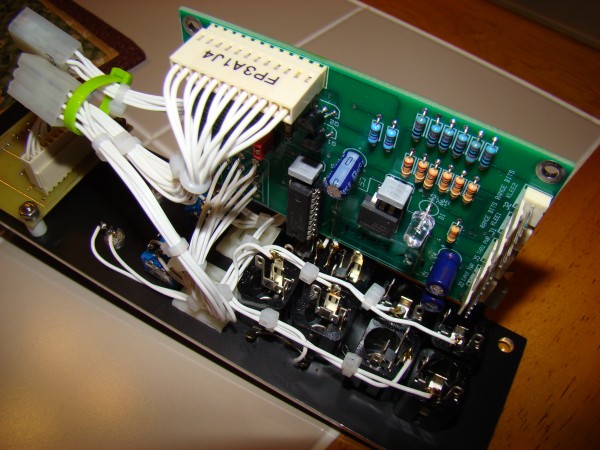
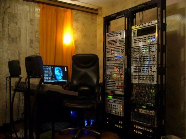
Wow, been checking all the recent builds and really liking what I see ! Here are a few pictures of a Dual Klee Sequencer voltage range display and synchronous load interface I build for a client recently. I threw in the Multis for good measure. A simple module but part of a much bigger build of two Klee sequencers.
Bill
DSC02676.JPG
Description:
Filesize:
1.69 MB
Viewed:
412 Time(s)
This image has been reduced to fit the page. Click on it to enlarge.
DSC02684.JPG
Description:
Filesize:
1.71 MB
Viewed:
434 Time(s)
This image has been reduced to fit the page. Click on it to enlarge.
DSC02678.JPG
Description:
Filesize:
1.83 MB
Viewed:
425 Time(s)
This image has been reduced to fit the page. Click on it to enlarge.
DSC02683.JPG
Description:
Filesize:
1.69 MB
Viewed:
403 Time(s)
This image has been reduced to fit the page. Click on it to enlarge.
Can't help that the mods are messy! Also, I had to wrap the data cable to the lcd with shielding because it was creating a high-frequency whine as it passed over some of the instruments.
Please don't ask why I had to cut out the main pcb to fit the lcd :S _________________ Sneak-Thief - raw electrofunk
Joined: Dec 02, 2010 Posts: 106 Location: Victoria BC
Posted: Tue Aug 30, 2011 8:04 pm Post subject:
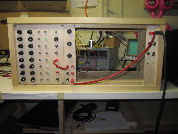
Here's my DIY modular in it's current early incarnation. So far just a baby 8 sequencer and Nicolas's LM324-based super-simple v/Hz VCO - http://electro-music.com/forum/topic-32689.html. The panels are 1/8" plywood. The cabinet is made from 3/4" pine board - the flooring type finished on just one side. The circuits are both on strip board. The baby-8 is my own layout, and the VCO layout is Nicolas's.
Next up:
- single transistor VCA - http://electro-music.com/forum/post-235297.html#235297
- simplest VCF I can come up with - any suggestions?
- lunetta-ish modules - Inventor's boolean sequencer etc with panels
- white noise
- actually i'm making this up as I go along
sonicmodular_mk1.jpg
Description:
Filesize:
376.84 KB
Viewed:
223 Time(s)
This image has been reduced to fit the page. Click on it to enlarge.
Joined: Dec 29, 2006 Posts: 1176 Location: australia
Audio files: 4
Posted: Wed Aug 31, 2011 5:04 pm Post subject:
Sonic wrote:
That's a nice looking machine Andrew. Would you mind talking us through what's in it?
Thanks - it is two sequencers. One has 4 stages but 16 CV outputs and 8 gate outputs.
The outputs all count in different ways, if the pots are labelled 1, 2, 3, 4; then the outputs will go
1234
2341
3412
4123
4321
3214
2143
1432
plus inverted versions of each and stages can be switched to turn on and off for certain intervals.
The other sequencer has 16 stages arranged in a 4x4 grid. It needs two clock signals, one to count horizontally, the other to count vertically. Plus up/down, left/right directions can be gate controlled. Reset also has special functions where the vertical count will reset to the binary inverse of the horizontal count and vice-versa. Feeding the gate outs into the reset inputs allows a huge variety of patterns to be created. Probably best to just watch the rather crappy vid, this was a paper-faced proto-type but functionally it is exactly the same
I am planning on a series of these panels - VCOs, filters, etc
Joined: Dec 02, 2010 Posts: 106 Location: Victoria BC
Posted: Wed Aug 31, 2011 7:11 pm Post subject:
Andrew, I've just spent a little while checking out your designs on sdiy.org What a lot of great stuff you've built!
I'm interested in building a bindubba1, with your permission of course. I love all pattern possibilities you squeeze out of 4 steps. I'll have to learn to etch pcbs, but so much the better.
Quote:
...plus inverted versions of each and stages can be switched to turn on and off for certain intervals.
If you don't mind me asking how do you do patch this kind of pattern exactly?
Joined: Dec 29, 2006 Posts: 1176 Location: australia
Audio files: 4
Posted: Wed Aug 31, 2011 8:18 pm Post subject:
of course, I would be very happy if you build one. i have one early version of the PCB sitting around, which i will never build. This is the one documented here - http://www.sdiy.org/pinky/data/bindubba1.html
a bit more work to build as plenty of wiring, but it has the added functions of "mix inputs" and staircase outs, which the new version does not have. PM if you want to buy it.
turning off stages is done with switches; outputs of the 4024 can be switched to periodically disable each 4052 (and therefore the CV outputs associated with that chip) as desired, DGTom called this "song sequencing"
you could easily make this patchable with some op amp comparators doing the enabling/disabling.
This is basically a repaneling of the Synthesis Technology MOTM 410 Triple Resonant Filter. I was asked to do this by a friend, and at first I was hesitant, because I really like Paul Schreiber's design on this and his other modules, but I also didn't think he'd mind, and so after some thought went ahead with it. It's basically identical to the original design, with the addition of the an input level selector switch, which is an option on the pcb.
i'll finish this prototype board and if it all works how the strip board did then i'll post the schematic for any one who wants it. everything i've learnt has been from here, and all the other synth freaks who are decent enough to share their work so i'm more than happy to do the same!
Joined: Aug 10, 2008 Posts: 270 Location: Salt Lake City, UT USA
Posted: Tue Sep 13, 2011 2:41 am Post subject:
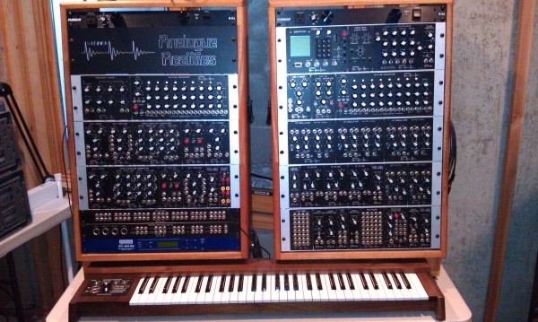
Got my Synthasystem finished. The top right rack is not "Steiner", but some nice extra modules. The MOTM Moog clone filter is now done except for two trimmers which are on their way. The keyboard is a DOT COM, great keyboard. I have the PCBs now for a Steiner duo-phonic keyboard which I hope to finish this year.
I started capturing and PCB layouts July/August 2010. Finished the last Steiner module last summer.
Steiner Modules:
2 ea 3x8 or 1x16/1x8 Studio Sequencers
1 ea Frequency Divider
2 ea Triple EG
4 ea VCA/Mixer
2 ea Voltage Processor
2 ea VC Trigger Generator
3 ea dual Voltage Followers
3 ea VCO Type A - Sine, Square/Pulse, Triangle, Saw
1 ea VCO Type B - Sine, Triangle
1 ea VCO Type B - Square, Saw
3 ea VCF (Synthasystem type, not Synthacon)
1 ea Phase Shifter
1 ea Ring Modulator
1 ea Peak Selector
1 ea Noise
1 ea Selective Inverter
1 ea Input Amplifier
1 ea Tuner/Monitor
Mine:
1 ea Trigger Converter (convert between S and Voltage triggers/gates)
YU Synth: Fixed Filter Bank
yusynth.net/Modular/index_en.html
This was built from the prototype pcb for this, so it's a bit different than the ones others will be using. The pcb bracket is made from a .40$ piece of roof flashing from home depot.
really nice SCM /RCD build sduck always liked the multi coloured
letterng that you do.
not looking forward to wiring mine as i too will have to do the same
to fit my panel size _________________ In an infinite universe one might very well
ask where the hell am I
oh yeah thats right the land of OZ
as good an answer as any
You cannot post new topics in this forum You cannot reply to topics in this forum You cannot edit your posts in this forum You cannot delete your posts in this forum You cannot vote in polls in this forum You cannot attach files in this forum You can download files in this forum

 Forum index » DIY Hardware and Software