| Author |
Message |
Tim Servo

Joined: Jul 16, 2006
Posts: 924
Location: Silicon Valley
Audio files: 11
|
|
|
Back to top
|
|
 |
feggster
Joined: Sep 12, 2011
Posts: 52
Location: uk
|
 Posted: Wed Jul 24, 2013 1:32 am Post subject: Posted: Wed Jul 24, 2013 1:32 am Post subject:
|
  |
|
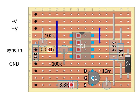
| bubzy wrote: | working  pcb layout confirmed :p pcb layout confirmed :p |
hi, looking at the pcb..where do the pots connect? do they use the same numbering as the schematic? |
|
|
Back to top
|
|
|
oculus
Joined: Oct 30, 2011
Posts: 35
Location: Iceland, Reykjavik
|
| Posted: Wed Jul 24, 2013 8:18 am Post subject:
Re: The LFX experimental LFO (8K LFO and Weird Waveshapers) |
|
|
| Tim Servo wrote: | Hi Oc,
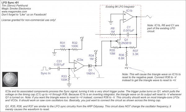
Yes, it's pretty easy to set up sync on this (or most other) LFOs by using an FET or an analog switch to change the charge on the timing cap. You can set up the circuit to pull the cap up to V+ or down to V-. In most triangle core oscillators, the integrator is inverting, so this means that pulling the timing cap up to V+ means the output triangle will be reset to V-. By the same token, pulling the cap down to V- means that the output wave will reset to its positive peak. It just depends on what behavior you prefer (or you could even put in a switch). The circuit below has already been posted on the Magic Smoke Facebook page (that's the place to go if you want to see this stuff a little sooner).
Tim (peaky!) Servo |
Nice thank you so much, can´t wait getting back home from the countryside to try this circuit out. |
|
|
Back to top
|
|
|
diablojoy

Joined: Sep 07, 2008
Posts: 809
Location: melbourne australia
Audio files: 11
|
| Posted: Wed Jul 24, 2013 7:27 pm Post subject:
|
|
|
Tim is there a reason for not pulling the intergrator cap to 0V ?
instead of the negative or positive rail
resetting the wave to 0V seems more intuitive to me
_________________
In an infinite universe one might very well
ask where the hell am I
oh yeah thats right the land of OZ
as good an answer as any |
|
|
Back to top
|
|
|
Tim Servo
Joined: Jul 16, 2006
Posts: 924
Location: Silicon Valley
Audio files: 11
|
Posted: Wed Jul 24, 2013 10:29 pm Post subject:
The LFX experimental LFO (8K LFO and Weird Waveshapers)
Subject description: A question of resets... |
|
|
Hey DJ,
In this design, you can reset the cap to 0V by connecting the 6.8K resistor to 0V. However, if you pull the cap to 0V, the output won't consistently reset. If the LFO wave was on the down slope, a reset to 0V will make the output start at 0V and head negative. On the other hand, if the LFO wave was on an upward slope, the reset will set the output to 0 and the it will start up. Resetting the LFO wave to the negative (or positive) peak means that the output behaves exactly the same way on every reset, regardless of where the LFO wave was when the sync pulse hits.
Tim (resetting it to 0K?) Servo |
|
|
Back to top
|
|
|
bubzy

Joined: Oct 27, 2010
Posts: 594
Location: United Kingdom
Audio files: 64
|
| Posted: Thu Jul 25, 2013 4:11 am Post subject:
|
|
|
| feggster wrote: |
hi, looking at the pcb..where do the pots connect? do they use the same numbering as the schematic? |
yep
_________________
_Richard_ |
|
|
Back to top
|
|
|
feggster
Joined: Sep 12, 2011
Posts: 52
Location: uk
|
| Posted: Thu Jul 25, 2013 2:17 pm Post subject:
|
|
|
| bubzy wrote: | | feggster wrote: |
hi, looking at the pcb..where do the pots connect? do they use the same numbering as the schematic? |
yep |
thanks, another great schematic and pcb to add to my to do list |
|
|
Back to top
|
|
|
diablojoy
Joined: Sep 07, 2008
Posts: 809
Location: melbourne australia
Audio files: 11
|
| Posted: Thu Jul 25, 2013 3:29 pm Post subject:
|
|
|
| Quote: | | In this design, you can reset the cap to 0V by connecting the 6.8K resistor to 0V. However, if you pull the cap to 0V, the output won't consistently reset. If the LFO wave was on the down slope, a reset to 0V will make the output start at 0V and head negative. On the other hand, if the LFO wave was on an upward slope, the reset will set the output to 0 and the it will start up. |
Thanks Tim
makes perfect sense.
I seem to remember seeing something along similar lines on the time machine schematic using a DG chip for resetting the LFO /EG to a known point and forcing a particular direction, would have to look it up again though to be sure.
_________________
In an infinite universe one might very well
ask where the hell am I
oh yeah thats right the land of OZ
as good an answer as any |
|
|
Back to top
|
|
|
bubzy
Joined: Oct 27, 2010
Posts: 594
Location: United Kingdom
Audio files: 64
|
|
|
Back to top
|
|
|
isak

Joined: Dec 13, 2009
Posts: 847
Location: Israel
Audio files: 18
|
| Posted: Thu Sep 26, 2013 10:13 am Post subject:
|
|
|
Hi Tim and Guys.
just wanted to make sure that the scheme that open this post is the last updated scheme of the 8k LFO, i'm asking cause i seen few schemes of the 8k in the forum
cheers,
Isak E.
_________________
http://www.myspace.com/mgmtrance |
|
|
Back to top
|
|
|
Tim Servo
Joined: Jul 16, 2006
Posts: 924
Location: Silicon Valley
Audio files: 11
|
| Posted: Thu Sep 26, 2013 10:19 am Post subject:
The LFX experimental LFO (8K LFO and Weird Waveshapers) |
|
|
Hey Isak,
Yes, that Rev 02 schematic is the latest and greatest (the only change I've made so far is to update the value of R5).
Happy building!
Tim (born with a soldering iron in my hand... my Mom never let me forget that) Servo |
|
|
Back to top
|
|
|
isak
Joined: Dec 13, 2009
Posts: 847
Location: Israel
Audio files: 18
|
| Posted: Thu Sep 26, 2013 3:02 pm Post subject:
|
|
|
| Quote: | | (the only change I've made so far is to update the value of R5) |
are you sure?
asking cause looking at your old 8k LFO scheme i see that C1 changed from 3300pF to 0.01uF.
and few resistors have changed as well.
i'm talking about this scheme..

i also want to add your cool sync scheme that i got from my other post.
is this the right way to do it?

one last thing...
can i output gate from the 8k LFO to gate say...ENV and to be able to control the gate speed with the rate pot?
if yes, please tell me from where?
thanks again Tim.
| Quote: | | Tim (born with a soldering iron in my hand... my Mom never let me forget that) Servo |
you killed me with that one 
EDIT:
if i got you correctly the VER2 is a summing of the next 3 schemes, right?
the waveshapes i saw in your Tube clip was amazing!!
i want them so much


_________________
http://www.myspace.com/mgmtrance |
|
|
Back to top
|
|
|
Tim Servo
Joined: Jul 16, 2006
Posts: 924
Location: Silicon Valley
Audio files: 11
|
| Posted: Thu Sep 26, 2013 4:26 pm Post subject:
The LFX experimental LFO (8K LFO and Weird Waveshapers) |
|
|
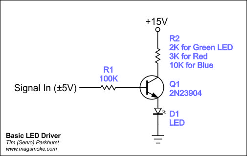
Yeah, I may be a little confused on the changes, but the Rev 02 is definitely the latest one. And yes, the LFX is a hybrid of the TSQ and 2x TSW waveshapers. I highly recommend adding an LED monitor (with transistor or op-amp buffer) to get some idea of what the output is doing. Also, you have the sync circuit hooked up correctly. Looks like you've got some fun building ahead of you!
Tim (building an LFO is a lovely way to spend a weekend) Servo |
|
|
Back to top
|
|
|
isak
Joined: Dec 13, 2009
Posts: 847
Location: Israel
Audio files: 18
|
| Posted: Fri Sep 27, 2013 12:21 am Post subject:
|
|
|
I will want to add a led indicator, I will come home later on and post the led scheme I have.
About the gate out to trigger ENV etc...is it possible to have?
cheers
_________________
http://www.myspace.com/mgmtrance |
|
|
Back to top
|
|
|
isak
Joined: Dec 13, 2009
Posts: 847
Location: Israel
Audio files: 18
|
|
|
Back to top
|
|
|
flab
Joined: Feb 13, 2012
Posts: 65
Location: Glasgow
|
| Posted: Sat Oct 12, 2013 4:56 am Post subject:
|
|
|
well, i think im really interesting to this as a vclfo ,with the sync part , same think you are looking for Isak , how are you going to apply a rate pot to it thought ?
cheers |
|
|
Back to top
|
|
|
isak
Joined: Dec 13, 2009
Posts: 847
Location: Israel
Audio files: 18
|
| Posted: Sat Oct 12, 2013 10:07 am Post subject:
|
|
|
Well, I did few mods to the attached layout here with illustrator.
Didn't build this yet, the rate is like the original I guess Or maybe remove the fine tune? Don't know yet.
I changed the timing cap to 2 timing caps, dont remember the values, I think the values are 0.1uF and 0.001uF with a switch for high and low speed.
I'll upload the scheme and the modified board as soon as I can, not at home at the moment.
The mods are the add on led and 2 timing caps.
Cheers.
_________________
http://www.myspace.com/mgmtrance |
|
|
Back to top
|
|
|
flab
Joined: Feb 13, 2012
Posts: 65
Location: Glasgow
|
| Posted: Wed Oct 16, 2013 10:39 am Post subject:
|
|
|
I built that yesterday , beautiful
thank you Tim
cheers |
|
|
Back to top
|
|
|
isak
Joined: Dec 13, 2009
Posts: 847
Location: Israel
Audio files: 18
|
| Posted: Wed Oct 16, 2013 10:45 am Post subject:
|
|
|
Hi flab.
Happy to hear you got this thing working
What did you eventually did with the fine tune/tune?
Did you used one of the layouts that attached to this post or directly from the scheme?
Cheers
_________________
http://www.myspace.com/mgmtrance |
|
|
Back to top
|
|
|
flab
Joined: Feb 13, 2012
Posts: 65
Location: Glasgow
|
| Posted: Wed Oct 16, 2013 11:09 am Post subject:
|
|
|
hiya,
well i kept both of them fine tune / tune ,
i added the sunc , a switch at R36
added three led indicators
also i think to place an 1M pot at the R1 so i can play with the tri offset ,
if am not mistaken, as long as is at my breadboard , |
|
|
Back to top
|
|
|
flab
Joined: Feb 13, 2012
Posts: 65
Location: Glasgow
|
| Posted: Thu Oct 17, 2013 3:34 am Post subject:
|
|
|
well what i said about R1 yesterday is all lies ,obviously is not working ,im sorry R1
also there is a think with the sync , can i change the 1n 914 diode with sth else ? like a equivalent one ? i think thats the think about my sync |
|
|
Back to top
|
|
|
feggster
Joined: Sep 12, 2011
Posts: 52
Location: uk
|
|
|
Back to top
|
|
|
Alfredo
Joined: Nov 20, 2008
Posts: 52
Location: Spain
|
| Posted: Sun Dec 16, 2018 11:43 am Post subject:
FINAL DESIGN PCB WITH WAVESHAPERS AND SYNC |
|
|
Hello! So there´s any final pcb design with Waveshapers and Sync function?
Thanks! |
|
|
Back to top
|
|
|
|

 Forum index » DIY Hardware and Software