| Author |
Message |
elmegil

Joined: Mar 20, 2012
Posts: 2179
Location: Chicago
Audio files: 16
|
 Posted: Tue Dec 16, 2014 6:05 pm Post subject: Posted: Tue Dec 16, 2014 6:05 pm Post subject:
|
  |
|
| The non-CMOS 555's will not work reliably at all. |
|
|
Back to top
|
|
 |
space_zulu
Joined: Dec 15, 2014
Posts: 13
Location: france
|
| Posted: Thu Dec 18, 2014 5:27 pm Post subject:
|
|
|
good evening everyone !
finally manage to get some sound after 4 days of testing, tweaking, and brain storming !
but there still some curious stuff ! i get kind of saw in the triangle out and kind of triangle in the saw out my square is way louder than every other waveforms and my oddest of all : i'm using my arturia microbrute pitch out to calibrate my 1V/oct response but i've got two problems my bandwidth goes from around 2k to 4/5kHz and then it goes down again to 2kHz, if i try to go up in frequency i got a bit of his then noting and if try to go below 2k i have hiss and pops before to get nothing
someone got an idea ? i tried to tweak de two trim pots HF and 1v/oct but the bandwidth stay the same may it be the timing cap ? |
|
|
Back to top
|
|
|
elmegil
Joined: Mar 20, 2012
Posts: 2179
Location: Chicago
Audio files: 16
|
| Posted: Thu Dec 18, 2014 6:26 pm Post subject:
|
|
|
| Did you start with the HF trim at its max setting (I think that's the correct end of the scale). |
|
|
Back to top
|
|
|
wackelpeter
Joined: May 05, 2013
Posts: 461
Location: germany
Audio files: 10
|
| Posted: Fri Dec 19, 2014 3:56 pm Post subject:
|
|
|
my VCO goes from very low (much less than 1Hz) an goes way above audible range... more than 20kHz...
You should start with the HF-Trimmer as suggested...
the Output of the square and saw is always louder as the sine and triangle with the same Output voltage... means 5vPP square is louder than 5vPP sine Signal...
you can adjust that mostly by changing the resistors between gnd and Output... for triangle R10 sine is R25 pulse is R8 for saw Change R33 in the Feedback path of IC4B...
if your sine Signal is to small you can follow the mods explained a few Posts/sites before...
for myself i adjusted the Levels of all Outputs to 5Vpp... which means sine and tri are a bit quieter but when i want to use more than 1 Signal i can adjust them via a mixing module (easy and effective Ken Stones DC Mixers)
when you wish to get the same volume on all signals with pulse being 5-6Vpp you have to raise tri and sine up to 10Vpp to have them at the same Level for yours ears and the "Feeling" they are equivalent... but as i do often use my signals with some of my "regular" analog stuff and it's capacities mostly can handle only 5Vpp signals i choosed to Keep them all at 5Vpp...
when your ramp isn't correct i would suggest to look after R19&R20 and surely the trimmer R37...
_________________
https://soundcloud.com/bastian-j |
|
|
Back to top
|
|
|
space_zulu
Joined: Dec 15, 2014
Posts: 13
Location: france
|
| Posted: Sun Dec 21, 2014 11:11 am Post subject:
|
|
|
well thank you all for your replies !
but for a mysterious reason, i don't get anymore sound now and i just get to much pissed off with it (sorry for this but after one week working night and day on it that's getting me crazy..) i hate to give up on something so maybe i'll try later to find the problem but for now i'm taking a small break.
i'm thinking about re-build it on a stripboard or even better if fonik as still two pcb of these to sell i'd be really glad of it !
I also think of making my own layout and etching my own pcb but i've never did this so i don't think it's a good starting project ^^'
sorry everyone for those silly question about my card as it might be a simple construction problem, at least i've learned a LOT of things and that's really a good thing.
thanks you guys  |
|
|
Back to top
|
|
|
fonik

Joined: Jun 07, 2006
Posts: 3950
Location: Germany
Audio files: 23
|
| Posted: Mon Dec 22, 2014 4:39 pm Post subject:
|
|
|
| space_zulu wrote: | i'm thinking about re-build it on a stripboard or even better if fonik as still two pcb of these to sell i'd be really glad of it !
I also think of making my own layout and etching my own pcb but i've never did this so i don't think it's a good starting project ^^' |
hi zulu.
you are correct. i would not ahve recommended this as a beginners project. the circuit is well tested, however, yo would need a scope to properly calibrate it, and if it comes to troubleshooting, a VCO is rather complex.
maybe you would learn the most if you fixed it, nevertheless, i can understand your frustration, been there before (more than once).
i do have a larger 4U prototype PCB (6x2in), completely stuffed. PM me if interested.
_________________

cheers,
matthias
____________
Big Boss at fonitronik
Tech Buddy at Random*Source |
|
|
Back to top
|
|
|
space_zulu
Joined: Dec 15, 2014
Posts: 13
Location: france
|
| Posted: Tue Dec 23, 2014 8:42 am Post subject:
|
|
|
thanks fonik for this answer ! that's kinda cheers me up ! 
however i DO want to make it work as i said, i just take a break to clear my brain ^^ i used scopes and i know approximately where the problem is, but i don't know what is the problem.
if i use a dc voltage source on the 1v/oct in i don't get anything but if i use any waveform (like a LFO for example) in it or in the expo fm in, i get something clear even if the waveforms outputs are not really good. i aslo know that if i press my finger on pin 5 of the LM13700 or pin 10 of the IC3 i got sound but not always frequencies changes.
with these information i know that basically the problem is around my expo converter but i can't understand why and also why i don't hear any sound if i don't press pin 5 or 10 of the 2 ICs, i just don't get what that means.
anyway i'll think about your offer and let you know later in pm when i'll have a bit of money saved (for now i'm bankrupted ^^) |
|
|
Back to top
|
|
|
drip.feed

Joined: Jul 11, 2012
Posts: 7
Location: Belfast, Northern Ireland
|
| Posted: Sat Dec 27, 2014 9:20 am Post subject:
|
|
|
Hi Matthias
Do you think I could use a different value for the Coarse and Fine tuning pots? I have 100K at the moment but the pots (I presume) are a bad batch because when I slowly rotate the Fine pot the frequency changes in little jumps - it isn't smooth. It makes calibrating this VCO maddeningly difficult. 
Or could there be any other component in the circuit that would cause small jumps in pitch CV instead of smooth changes?
_________________
Dripfeed |
|
|
Back to top
|
|
|
wackelpeter
Joined: May 05, 2013
Posts: 461
Location: germany
Audio files: 10
|
| Posted: Sat Dec 27, 2014 11:50 am Post subject:
|
|
|
as they are acting as a voltage divider i think you can use other values too...
Changing the resistors afterwards them R54 and R29 will change the Impact of frequency tuning when you turn the pots...
p.s. do you use linear pots? sounds also a bit like you're using logarithmic pots... well it's not stepped then but will react first slowly and then changes rapidly when turning the pot...
_________________
https://soundcloud.com/bastian-j |
|
|
Back to top
|
|
|
drip.feed
Joined: Jul 11, 2012
Posts: 7
Location: Belfast, Northern Ireland
|
| Posted: Sun Dec 28, 2014 5:55 am Post subject:
|
|
|
| wackelpeter wrote: | | do you use linear pots? sounds also a bit like you're using logarithmic pots... well it's not stepped then but will react first slowly and then changes rapidly when turning the pot... |
Thanks. Yes they are linear (B100K).
It is a weird behaviour.
I rotate the pot very slowly about 1 or 2 degrees - the frequency meter does not change.
I rotate some more, slowly, a tiny amount - the frequency meter does not change.
And again, I rotate - the frequency meter suddenly jumps to a different frequency.
It is the same whether I rotate the pot clockwise or counterclockwise.

| wackelpeter wrote: | | Changing the resistors afterwards them R54 and R29 will change the Impact of frequency tuning when you turn the pots. |
If I use a higher value for R54 will that reduce the range of the Fine pot?
_________________
Dripfeed |
|
|
Back to top
|
|
|
blue hell
Site Admin

Joined: Apr 03, 2004
Posts: 24432
Location: The Netherlands, Enschede
Audio files: 297
G2 patch files: 320
|
| Posted: Sun Dec 28, 2014 8:39 am Post subject:
|
|
|
| drip.feed wrote: | | And again, I rotate - the frequency meter suddenly jumps to a different frequency. |
Do you have another oscillating thing on the same power supply?
This may cause frequency locking when power supply noise rejection is not too good, causing one oscillator to sync with another.
_________________
Jan
also .. could someone please turn down the thermostat a bit.
 |
|
|
Back to top
|
|
|
wackelpeter
Joined: May 05, 2013
Posts: 461
Location: germany
Audio files: 10
|
| Posted: Sun Dec 28, 2014 8:41 am Post subject:
|
|
|
| drip.feed wrote: |
If I use a higher value for R54 will that reduce the range of the Fine pot? |
yes the higher the resistor is the smaller the range...
have you measured the behavior of your pots with an Ohmmeter? i mean to be sure that These pots are okay? you should measure a steady increasing or decreasing resistance (depends on which lugs of the pot you measure)
as i guess they are 270 degree pots you should measure at 135 50 k to each lug from Center wiper... 67 degree 25K on one and 75 k on the other and so on...
maybe check with an alternate pot if they react likewise...
btw. have you calibrated the whole thing already? if there's some faulty thing in your Expo converter then it should behave somewhat identical with your 1v/oct Input... means that there would be much bigger octave jumps as expected...
_________________
https://soundcloud.com/bastian-j |
|
|
Back to top
|
|
|
drip.feed
Joined: Jul 11, 2012
Posts: 7
Location: Belfast, Northern Ireland
|
| Posted: Sun Dec 28, 2014 10:21 am Post subject:
|
|
|
Thanks guys...I'm virtually certain now it is the pot. I replaced it with a different brand pot and that is much smoother.
So I need to buy some new pots. Grrrrr...Alpha! 
_________________
Dripfeed |
|
|
Back to top
|
|
|
Antichambre

Joined: Oct 14, 2013
Posts: 2
Location: France
|
| Posted: Sat Dec 26, 2015 2:09 am Post subject:
|
|
|
Hi Everybody,
I've got a little question...
On my circuit the sync seems to restart the period somewhere in the negative part of the oscillation.
Is it normal?
Is there a way to force it restart at the exact zero crossing?
Thank you... |
|
|
Back to top
|
|
|
lysergist
Joined: Jan 14, 2016
Posts: 36
Location: France
Audio files: 2
|
| Posted: Tue Jun 14, 2016 12:37 pm Post subject:
|
|
|
Hi !
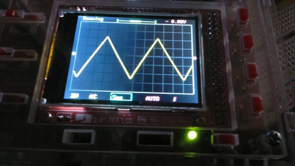
I don't know if PCBs are still available, and i have all the components, so i decided to try a stripboard version. I know i should etch, maybe soon.
So... that's my first stripboard EVER. Really hard to make it compact and to save some place. But it fits perfecly in my board (9x15cm).
Triangle, Sine and Pulse are perfectly stable, the sine seems to be a little bit weak but that's how it's designed i guess.
| Description: |
|
| Filesize: |
385.03 KB |
| Viewed: |
456 Time(s) |
| This image has been reduced to fit the page. Click on it to enlarge. |

|
| Description: |
|
| Filesize: |
1.31 MB |
| Viewed: |
226 Time(s) |
| This image has been reduced to fit the page. Click on it to enlarge. |
|
| Description: |
|
| Filesize: |
1.24 MB |
| Viewed: |
235 Time(s) |
| This image has been reduced to fit the page. Click on it to enlarge. |

|
Last edited by lysergist on Thu Jul 22, 2021 5:54 am; edited 2 times in total |
|
|
Back to top
|
|
|
elmegil
Joined: Mar 20, 2012
Posts: 2179
Location: Chicago
Audio files: 16
|
| Posted: Tue Jun 14, 2016 6:35 pm Post subject:
|
|
|
Congratulations!
The PCBs are supposed to be, or soon be, back in stock at the usual places (thonk, synthcube) but there is nothing wrong with doing it yourself all the way down to stripboard. |
|
|
Back to top
|
|
|
qfactor
Joined: Jul 19, 2010
Posts: 9
Location: Singapore
|
| Posted: Fri Jul 01, 2016 10:17 pm Post subject:
|
|
|
I've been trying to help a friend fix his VCO555 Eurorack version for some time now and am at wits end trying to figure out what's wrong with it!
Have since reflowed solder (quite a few times already, actually!) to ensure that there're no cold joints.
I also have my own working VCO555 that I've swapped the different combinations of boards and chips, and essentially, anything swapped to his, from mine, don't work on his module.
In short, all his chips work but his circuit pcb doesn't (even his panel pcb does work when joined to my circuit pcb. And yes, it's using the CMOS 555!
So this narrows down to his main pcb. The power supply going into all the IC chips are going in correct, so I figured (I'm a noob at fixing, so am trying this as a 1st project!) I'd try to see if I could at least pick up any sound coming off Pin 7 of the 555 or after Pin 1 of IC4a (TL074). Nothing came off it. Tried to measure and got a 5v DC coming out of it only. AC was like 0.001v or something.
In fact ALL waveform outs did not produce any audio and I could only measure DC voltages (between 2-5v DC).
Could it be deduced as there's no oscillation going on at all? And where else should I check to find a fault? I understand, reading this thread, that C4(2200pF) charges and discharges that causing an oscillation? How do I measure this, to see if there's anything going on there?
Thank you! |
|
|
Back to top
|
|
|
elmegil
Joined: Mar 20, 2012
Posts: 2179
Location: Chicago
Audio files: 16
|
| Posted: Fri Jul 01, 2016 10:39 pm Post subject:
|
|
|
What's going on with C4? That's the main timing cap.
If you don't have a scope of some sort, it sounds like you're going to need it.
Honestly, I don't know exactly how this circuit is supposed to behave, but if yours is still working after all the swapping around, I'd compare point by point.
If I had to guess, I'd say that there's a short somewhere, possibly use your meter to find if anything that isn't supposed to go to ground is gong to ground. |
|
|
Back to top
|
|
|
alanwilder81
Joined: Sep 03, 2016
Posts: 310
Location: italy
|
|
|
Back to top
|
|
|
fonik
Joined: Jun 07, 2006
Posts: 3950
Location: Germany
Audio files: 23
|
| Posted: Wed Dec 28, 2016 2:16 pm Post subject:
|
|
|
| alanwilder81 wrote: | | am i right in assuming that on the LM13700 the output is the pin 5 and the bias input is pin 1 ? The inverting and non inverting input are quite obvious,so is that really it to get the pins matching right ? |
yes.
_________________
cheers,
matthias
____________
Big Boss at fonitronik
Tech Buddy at Random*Source |
|
|
Back to top
|
|
|
alanwilder81
Joined: Sep 03, 2016
Posts: 310
Location: italy
|
| Posted: Wed Dec 28, 2016 2:38 pm Post subject:
|
|
|
| thanks man |
|
|
Back to top
|
|
|
alanwilder81
Joined: Sep 03, 2016
Posts: 310
Location: italy
|
| Posted: Mon Jan 09, 2017 12:09 pm Post subject:
|
|
|
hello all,
I breadboarded the 555 VCO. I replaced the specified TL074 with TL084.
It's incredibly noisy, almost like when you touch a VCO component with your finger and you get a distinct ,similar noise.
in my case is less obvious but you get the idea.
Also, i have a problem with the PWM. The pitch varies according to the pulse width variation.
any ideas? thanks |
|
|
Back to top
|
|
|
fonik
Joined: Jun 07, 2006
Posts: 3950
Location: Germany
Audio files: 23
|
| Posted: Mon Jan 09, 2017 12:44 pm Post subject:
|
|
|
when your pitch is onfluenced by the PWM then there is something wrong in general. Some issue with 0V/GND maybe? this could also be a reason for the noisy output.
i would focus on the PWM/Ptch issue first.
_________________
cheers,
matthias
____________
Big Boss at fonitronik
Tech Buddy at Random*Source |
|
|
Back to top
|
|
|
alanwilder81
Joined: Sep 03, 2016
Posts: 310
Location: italy
|
| Posted: Mon Jan 09, 2017 2:35 pm Post subject:
|
|
|
| thanks |
|
|
Back to top
|
|
|
alanwilder81
Joined: Sep 03, 2016
Posts: 310
Location: italy
|
| Posted: Mon Jan 09, 2017 2:38 pm Post subject:
|
|
|
| the noise disappears when i physically touch ground. For instance,it clears up when i touch any grounded resistor leg |
|
|
Back to top
|
|
|
|

 Forum index » DIY Hardware and Software » Thomas Henry designs

