| Author |
Message |
Phallus Dei
Joined: Jan 21, 2007
Posts: 18
Location: Scotland, UK
|
 Posted: Sat Jul 07, 2007 12:44 pm Post subject: Posted: Sat Jul 07, 2007 12:44 pm Post subject:
|
  |
|
I'm running Maplin out of capacitors!
This is my work thus far. Are those wima capacitors ok? I will whip them out quick as lightening if they aren't!

[editor's note: fixed the link to your image. You need to use the IMG tag you must link directly to the image file, not a web page that shows the file. --mosc] |
|
|
Back to top
|
|
 |
Phallus Dei
Joined: Jan 21, 2007
Posts: 18
Location: Scotland, UK
|
| Posted: Mon Jul 09, 2007 10:19 am Post subject:
|
|
|
Those WIMA caps are already out, I saw more appropriate caps on the net on Maplin's website. Those caps (the Wimas) are for stratocaster style guitars! You can see I extended the legs.
One question, is the red bell-wire ok for the jumpers? |
|
|
Back to top
|
|
|
mosc
Site Admin

Joined: Jan 31, 2003
Posts: 18260
Location: Durham, NC
Audio files: 228
G2 patch files: 60
|
| Posted: Mon Jul 09, 2007 10:50 am Post subject:
|
|
|
Most bell wire I've seen is solid conductor which works fine electrically but can break after a few repeated bendings. If your wire is stranded, it will be fine.
_________________
--Howard
my music and other stuff |
|
|
Back to top
|
|
|
Uncle Krunkus
Moderator

Joined: Jul 11, 2005
Posts: 4761
Location: Sydney, Australia
Audio files: 52
G2 patch files: 1
|
| Posted: Mon Jul 09, 2007 3:54 pm Post subject:
|
|
|
I like the WIMAs, they're cool. 
_________________
What makes a space ours, is what we put there, and what we do there. |
|
|
Back to top
|
|
|
Phallus Dei
Joined: Jan 21, 2007
Posts: 18
Location: Scotland, UK
|
| Posted: Tue Jul 10, 2007 9:27 am Post subject:
|
|
|
Ok cool. I put the WIMAS back in temporarily, as I got the other components together, but the thing is astonishingly quiet.
How do I get this thing louder? |
|
|
Back to top
|
|
|
Uncle Krunkus
Moderator
Joined: Jul 11, 2005
Posts: 4761
Location: Sydney, Australia
Audio files: 52
G2 patch files: 1
|
| Posted: Tue Jul 10, 2007 5:13 pm Post subject:
|
|
|
There must be something amiss about the wiring, 'cos mine pumped out plenty of signal. Eventually.
Make sure you're using the right Hex Schmitt Trigger, it needs to be a (CD?)40106, a (CD?)4584 or a 74C14. Don't use a 74HC14! These aren't rated for 9V, and you will be listening to your chip being slow roasted!  (the level will be low as well) (the level will be low as well)
BTW I did this myself, that's why I know. 
_________________
What makes a space ours, is what we put there, and what we do there. |
|
|
Back to top
|
|
|
Phallus Dei
Joined: Jan 21, 2007
Posts: 18
Location: Scotland, UK
|
| Posted: Wed Jul 11, 2007 8:44 am Post subject:
|
|
|
I'm using a CD40106, just as the doctor ordered. I will check the components when I get replacements for those WIMA 0.022 caps. Maybe once I get those suckers out (with their home-made legs!) it might be louder.
Could be a cold solder. I'll replace every matte finish solder in the thing if necessary!
Good news is the filter works, its just a little bit nasty to listen to! |
|
|
Back to top
|
|
|
Phallus Dei
Joined: Jan 21, 2007
Posts: 18
Location: Scotland, UK
|
| Posted: Wed Jul 11, 2007 12:26 pm Post subject:
|
|
|
Ok I got it working "perfectly". I need to post a youtube video.
Basically it was quiet, and all you could hear was a choir of naughty oscilators. So... I circuitbent it. I found a connection which totally boosted the output. This also cleared the multiple oscillator fiasco.
I also managed to install some kind of ringmodulator to it! How in the hell?!?!
Its a gem though. And seriously, if you make one and no sound comes out, then something really is up! I had a capacitor fall off the board today, and it works fine without!!! |
|
|
Back to top
|
|
|
mosc
Site Admin
Joined: Jan 31, 2003
Posts: 18260
Location: Durham, NC
Audio files: 228
G2 patch files: 60
|
| Posted: Wed Jul 11, 2007 2:02 pm Post subject:
|
|
|
PD, you're on your way to becoming an electrical engineer. 
_________________
--Howard
my music and other stuff |
|
|
Back to top
|
|
|
Phallus Dei
Joined: Jan 21, 2007
Posts: 18
Location: Scotland, UK
|
| Posted: Thu Jul 12, 2007 11:38 am Post subject:
|
|
|
Funny you should say that... I got a volume pot in it now, because I actually sat down and worked out how to fit it! I usually just dive in with the iron.
I also fitted a battery kill-switch to actually turn the thing on and off. |
|
|
Back to top
|
|
|
Phallus Dei
Joined: Jan 21, 2007
Posts: 18
Location: Scotland, UK
|
| Posted: Fri Jul 13, 2007 8:24 am Post subject:
|
|
|
Ok. The thing is nearly finished.


Some very VERY densely packed wires!
 |
|
|
Back to top
|
|
|
Narbotic

Joined: Jun 24, 2007
Posts: 51
Location: Brooklyn, US
|
| Posted: Tue Jul 31, 2007 2:28 am Post subject:
|
|
|
That is the cutest case I have ever seen. 
Love those switches!
Love those dots!
_________________
- Collin Mel |
|
|
Back to top
|
|
|
mrsteve81
Joined: Aug 01, 2007
Posts: 2
Location: Luton, UK
|
| Posted: Wed Aug 01, 2007 6:26 am Post subject:
|
|
|
I've been lurking in the shadows of this forum for a while now.
Thought I should join and give thanks for all the advice I've stolen from everyone who has posted in this topic.
Not finished building it yet but I've got the caps in place and about half the resistors.
I do have 1 question though. As this was my first electrical project, (Apart from bending a Speak & Spell) I didn't mount the ICs on sockets. Just wanted to know if its probably that I've burnt the chips?
I've got a spare 1 of each so it wont be too much of a problem to replace them I'm just blaming inexperience for my stupidity
If I can get this working I think I'll give the soundlab a go next. Might as well jump in at the deep end. |
|
|
Back to top
|
|
|
hackbox

Joined: Jul 27, 2007
Posts: 134
Location: Australia
|
| Posted: Sat Aug 04, 2007 10:38 pm Post subject:
|
|
|
Sooooooo Hello folks.
New round these parts.
Built a few of Ray's modules and have got 'em working first go, but this WSG has got me stumped.
Its a little less then half working.
I'm using the Uncle Krunkus stripboard layout.
I cheated and resized it to fit as a sort of "poor man's pcb".
My first problem is that the Pitch knob isn't working on the WSG 1 side of the board but all the others are all fine and its making some sounds that are quite cool when gated through my microkorg arpeggiator and other modules.
The WSG 2 on the other hand doesn't do anything at all.
Now I've been over and over the board and can't find where I've gone wrong. The only thing I can think of is that I've put in the electrolytics in backward on that side.
Does anyone have any ideas?
Oh and this comes on the day that I find out Ray has released a WSG PCB!
Thanks in advance for your help.
Cheers
A |
|
|
Back to top
|
|
|
blue hell
Site Admin

Joined: Apr 03, 2004
Posts: 24499
Location: The Netherlands, Enschede
Audio files: 298
G2 patch files: 320
|
| Posted: Wed Aug 08, 2007 1:36 pm Post subject:
|
|
|
| mrsteve81 wrote: | | Just wanted to know if its probably that I've burnt the chips? |
With soldering? Probably not, it takes quite something to do that for the usual chips.
And  of course. of course.
_________________
Jan
also .. could someone please turn down the thermostat a bit.
 |
|
|
Back to top
|
|
|
mrsteve81
Joined: Aug 01, 2007
Posts: 2
Location: Luton, UK
|
| Posted: Tue Aug 21, 2007 5:46 pm Post subject:
|
|
|
Thanks for the advice. I can now mark that off as a reason its not working!
Been in Spain for 2 weeks so please excuse my late thanks. |
|
|
Back to top
|
|
|
dobart

Joined: Feb 20, 2007
Posts: 10
Location: SEATTLE
|
| Posted: Thu Oct 25, 2007 4:03 pm Post subject:
|
|
|
| dobart wrote: | | Uncle Krunkus wrote: | I remember Ray saying something about the cap which backs up the pseudo split supply, when someone had a similar problem. Make sure that cap is the right way around. By pseudo split supply, I mean the arrangement for the 741 which is the heart of the filter. I just had a look, and it's C7.
The symptoms you describe sound like what happens when an electrolytic is reverse biased. The dielectric breaks down and behaves "differently", and can sometimes be re-polarized, in which case it sounds better for a few seconds, but then ultimately fails and goes weird again etc. You're lucky it hasn't actually gone "pop" |
Maybe the transistor is doing something to the output waveform the way it mixes in that long wavelength? I have to get a scope on it at some point, but I'm off on a work trip for the week.
If I can figure it out for my next stripbpard core (to mount in a handheld geiger counter, with all the controls and LDRs: mount the LEDs into goggles connected to the handheld unit via cable!) I'd like to use it. |
I got this to work fine, BTW, clocking a CD4040 with the WSG output. It does seem to be a little finicky about range, but a few resistors in the right places would fix that. Here's messing around with this playing with vactrol filter possibilities:
http://www.youtube.com/watch?v=-kSlUghiqZI |
|
|
Back to top
|
|
|
Makaaberi
Joined: Apr 18, 2008
Posts: 7
Location: Finland
|
|
|
Back to top
|
|
|
jamboy
Joined: May 12, 2008
Posts: 4
Location: London
|
| Posted: Tue May 13, 2008 4:39 am Post subject:
|
|
|
Hi all,
I've built the WSG as my first project and it's all gone surprisingly well. However mine doesn't quite sound like some of the youtube vids posted here.
The issues is I get "static" sound when I rub my finger around the top strip. Isolated on the section of circuit from R4 > C2 > connectors linked to IC2 > C3 and the connectors of the actual Pot
Am I right in thinking that the Caps are 471k ceramics?? This seems to be the only bit of the circuit that has issues. All my wiring and holes are correct as far as I can tell.
Could it be an issue with the components? The noise only starts on the top leg of R4 not the bottom and ends before R16.
Other than that I'm very happy and am looking for more stripboards to make. Thanks to anyone who may be able to help |
|
|
Back to top
|
|
|
mosc
Site Admin
Joined: Jan 31, 2003
Posts: 18260
Location: Durham, NC
Audio files: 228
G2 patch files: 60
|
|
|
Back to top
|
|
|
amplex

Joined: May 26, 2008
Posts: 64
Location: sacramento, ca
Audio files: 6
|
Posted: Mon May 26, 2008 5:13 pm Post subject:
 first time poster wsg questions first time poster wsg questions
Subject description: stripboard layout |
|
|
hey its my first time posting on here, been lurking for a couple weeks, and finally started putting together the stripboard layout (i know very little about electronics, this is my 2nd diy project (besides some circuitbent toys), i built a dual 555 apc on breadboard and then a boardless one lol). I'm currently doing the WSG stripboard layout on perfboard and wirewrapping the connections (tedious!!). I'm just missing 2 20nf caps now i think..
I was wondering about the MKS designation on the 20nf & 100nf caps, first off, 100nf is .1uf right? will a .1uf ceramic cap work?
at ripoff shack (aka radio shack) i found a metal film cap that says 250v 1.0uf on it, is this going to work for c26? I cant tell if this MF cap is polarized I dont see a + or - anywhere =[
also I have a 1m ohm 2% 2w resistor will that work in place of the 1/4w 5% 1m? not sure about the wattage or % indicators .. like i said, im a newb =]
also I'm wondering about the stripboard layouts that have a couple caps lying across the stripboard lines, I'm guessing that you just leave a space in the middle and connect to the upper and lower trace, and thats why it looks that way (i.e C6, C26, T1, T21)..
Also one other noob question, if you dont have a .02uf cap (20nf right?) can you use 2 .01uf caps in-line like (i've read) you can with resistors? also what would happen if you used a ceramic cap in the place of an electrolytic (or vice versa)? Are these differences of cap type just made to handle higher voltages or do they have different functions?
Thanks for all your pics, designs, layouts and Q&A sessions, you guys are gods to me and I'm learning a lot =]
also i have some trance / experimental music on www.myspace.com/jnabeats if anyones interested, drop me a line if you like it |
|
|
Back to top
|
|
|
blue hell
Site Admin
Joined: Apr 03, 2004
Posts: 24499
Location: The Netherlands, Enschede
Audio files: 298
G2 patch files: 320
|
| Posted: Mon May 26, 2008 7:01 pm Post subject:
|
|
|
amplex.
_________________
Jan
also .. could someone please turn down the thermostat a bit.
|
|
|
Back to top
|
|
|
fluxmonkey
Joined: Jun 24, 2005
Posts: 708
Location: cleve
|
Posted: Mon May 26, 2008 7:42 pm Post subject:
Re: first time poster wsg questions
Subject description: stripboard layout |
|
|
| amplex wrote: | hey its my first time posting on here, been lurking for a couple weeks, and finally started putting together the stripboard layout (i know very little about electronics, this is my 2nd diy project (besides some circuitbent toys), i built a dual 555 apc on breadboard and then a boardless one lol). I'm currently doing the WSG stripboard layout on perfboard and wirewrapping the connections (tedious!!). I'm just missing 2 20nf caps now i think..
I was wondering about the MKS designation on the 20nf & 100nf caps, first off, 100nf is .1uf right? will a .1uf ceramic cap work? |
yep. handy chart for capacitor conversion here
| amplex wrote: | at ripoff shack (aka radio shack) i found a metal film cap that says 250v 1.0uf on it, is this going to work for c26? I cant tell if this MF cap is polarized I dont see a + or - anywhere =[
also I have a 1m ohm 2% 2w resistor will that work in place of the 1/4w 5% 1m? not sure about the wattage or % indicators .. like i said, im a newb =] |
resistor will be fine, if it will physically fit... you can always sub a higher tolerence (lower percent ) component for a lower precision one; or a higher wattage for a lower wattage. cap should be ok, too, but it'll probably be a bit big (physical size)
| amplex wrote: | | also I'm wondering about the stripboard layouts that have a couple caps lying across the stripboard lines, I'm guessing that you just leave a space in the middle and connect to the upper and lower trace, and thats why it looks that way (i.e C6, C26, T1, T21).. |
:
C6 & C26 both connect to the negative power and one end of a 1meg pot, w/ no connection to the the trace in between. T1 & T21 have 3 connecitons, to 3 separate traces. it's a little confusing because the component outlines don't look quite as wide as they should be.
| amplex wrote: | | Also one other noob question, if you dont have a .02uf cap (20nf right?) can you use 2 .01uf caps in-line like (i've read) you can with resistors? also what would happen if you used a ceramic cap in the place of an electrolytic (or vice versa)? Are these differences of cap type just made to handle higher voltages or do they have different functions? |
resistor values add together if you connect them in series (end to end); but for caps, you need to connect them in parrallel (connect 1 lead from each cap together, then connect the remaining 2 leads together).
electrolytics are generally higher values (1uf or more), and you need to watch polarity. ceramics are non-polarized so nothing to worry about. there's some overlap; usually you won't find ceramics much bigger than 5uf, nor electroltics much smaller than 1uf. i usually use the recommended type, rather than worry about it.
good luck!
bbob |
|
|
Back to top
|
|
|
amplex
Joined: May 26, 2008
Posts: 64
Location: sacramento, ca
Audio files: 6
|
Posted: Thu May 29, 2008 1:47 pm Post subject:
 wsg debugging issues wsg debugging issues |
|
|
thanks for the help bbob, sry for repeating questions that had already been covered in the thread multiple times..
so I finally spent about 8 hours yesterday trying to wirewrap this stripboard layout on perfboard, and halfway through the middle i realized that the 14pin socket i used for the 40106 has pins that are too short to wirewrap, so I had to break down and solder little pieces of wire across those strips, which went much quicker except for when I got shaky and accidently removed the soldered in place wires (very frustrating)! so anyway, I got the thing done, and of course it doesnt work, doesnt make any sound except for a very slight hum, unless i touch the output capacitor to traces further down the board. the right side doesnt seem to work unless i touch the capacitor to those traces, and i might have fried a 40106 by putting it in backwards (lucky i bought 20 cause im a noob haha)
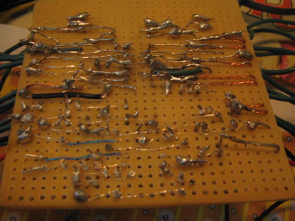
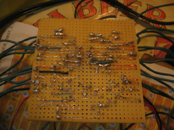
anyway, not sure what to do next, ive been tracing all soldered and wirewrapped connections making sure everything is soldered together and right, all the cuts in the traces are in the right spots and everything has the right number of solder points (thanks again for the reverse image of the stripboard), so anyway I have these somewhat fuzzy pictures, maybe someone will notice something obviously wrong. any ideas on how to trace down the circuit with a multimeter to see whats not connected? just do a voltage test with the thing running (follow the positive line) and the first spot in the circuit that reads 0 is unconnected right?
attached are pics of my realllly bad soldering but nothing is touching, no solder in between nodes on the perfboard, i scratched in between the close ones with a needle just in case, im thinking i have a component in wrong or am missing a connection somewhere, but it looks like the diagram (except c25 i had to use 2 .01s instead, but i put them as instructed, side by side, as well as the first three connections on the negative rail (by the battery) i accidently moved 1 slot down, but they are connected to the right spot on the bottom, and the top is connected to negative like it should be) everything else appears to be correct.. HELP i want this to work, im obcessed now =x maybe my diodes are backwards? they look right.. all the polarized caps are in right, possibly my lm471 is backwards? the writing on the chip faces left (from the stripboard layout view) for the 40106 and right for the 471 and i have seen them all the same way in the other. i hope the 471 isnt backwards. i didnt put that one in a socket lol ..
pre-emptive thank yous for your time and brain cycles =]
also im realizing the filter circuit is pretty small for this. im wondering if i can use the filter with an input , where would i route the incoming audio?
| Description: |
|
| Filesize: |
62.43 KB |
| Viewed: |
2115 Time(s) |
| This image has been reduced to fit the page. Click on it to enlarge. |
|
| Description: |
|
| Filesize: |
67.53 KB |
| Viewed: |
2109 Time(s) |
| This image has been reduced to fit the page. Click on it to enlarge. |
|
| Description: |
|
| Filesize: |
57.52 KB |
| Viewed: |
2089 Time(s) |
| This image has been reduced to fit the page. Click on it to enlarge. |
|
| Description: |
|
| Filesize: |
66.34 KB |
| Viewed: |
2141 Time(s) |
| This image has been reduced to fit the page. Click on it to enlarge. |
|
|
|
|
Back to top
|
|
|
amplex
Joined: May 26, 2008
Posts: 64
Location: sacramento, ca
Audio files: 6
|
| Posted: Thu May 29, 2008 2:12 pm Post subject:
c7 backwards |
|
|
| so going back through the old posts one more time i realized that C7 was reversed on my board. Usually they signify the positive on these electrolytic caps but this one had negative signified.. anyway, i reversed the cap and still have the same problems, no output unless i bridge from around the 40106 to the output capacitor. and its really quiet when i do that. im thinking my 741 is backwards =[[ |
|
|
Back to top
|
|
|
|

 Forum index » DIY Hardware and Software » MusicFromOuterSpace.com designs by Ray Wilson
