| Author |
Message |
electri-fire
Joined: Jul 26, 2006
Posts: 536
Location: Dordrecht NL
Audio files: 4
G2 patch files: 4
|
 Posted: Wed Nov 25, 2009 9:48 am Post subject:
Zeitgeist Schematics Posted: Wed Nov 25, 2009 9:48 am Post subject:
Zeitgeist Schematics |
  |
|
I asked for the Zeitgeist schematics, but....
Edit: I just remembered Rob mailed them to me. As he also posted the Benjolin schematics I presume he won't mind me posting the Zeitgeist.
| Description: |
|
| Filesize: |
111.69 KB |
| Viewed: |
2877 Time(s) |
| This image has been reduced to fit the page. Click on it to enlarge. |
|
| Description: |
|
| Filesize: |
72.5 KB |
| Viewed: |
1965 Time(s) |
| This image has been reduced to fit the page. Click on it to enlarge. |
|
| Description: |
|

Download (listen) |
| Filename: |
ZeitgeistSchematic.pdf |
| Filesize: |
34.07 KB |
| Downloaded: |
4217 Time(s) |
|
|
|
Back to top
|
|
 |
Ginsengbob
Joined: Jul 04, 2011
Posts: 3
Location: Alabama United States
|
| Posted: Mon Jul 04, 2011 12:59 pm Post subject:
This May be a stupid question but...... |
|
|
How can you use the board graphic for making a pcb when it's got the component graphics on it like that?
Thanks |
|
|
Back to top
|
|
|
CJ Miller

Joined: Jan 07, 2007
Posts: 368
Location: 127.0.0.1
|
| Posted: Thu Mar 15, 2012 5:48 am Post subject:
|
|
|
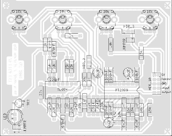
| I noticed a small error on the schematic diagram. It has C9 - pin 9 on the delay chip - as 9100nF. Looking at the overlay and photo here it appears that the extra 9 is a typo, it should probably be 100nF. |
|
|
Back to top
|
|
|
Ginsengbob
Joined: Jul 04, 2011
Posts: 3
Location: Alabama United States
|
| Posted: Fri Mar 16, 2012 10:43 am Post subject:
Seriously |
|
|
On the Benjolin post there is a graphic with the components and a graphic for using a transfer with no components to print on the transfer paper.
Is there something I'm missing?
Please tell me.
Thanks |
|
|
Back to top
|
|
|
PickNick

Joined: Oct 16, 2009
Posts: 82
Location: BP
|
| Posted: Sun Mar 18, 2012 9:21 am Post subject:
|
|
|
i'm still not sure what kind of regulator is 1702...
mcp1702?
can i use 7805?
_________________
Allow theex.nl |
|
|
Back to top
|
|
|
inlifeindeath

Joined: Apr 02, 2010
Posts: 316
Location: Albuquerque, NM
|
| Posted: Sun Mar 18, 2012 10:14 am Post subject:
|
|
|
| PickNick wrote: | i'm still not sure what kind of regulator is 1702...
mcp1702?
can i use 7805? |
yes, it's just a 5v line for the delay chip. 7805 work fine.
_________________
http://www.youtube.com/user/borisandfef |
|
|
Back to top
|
|
|
PickNick
Joined: Oct 16, 2009
Posts: 82
Location: BP
|
| Posted: Mon Mar 19, 2012 7:49 pm Post subject:
|
|
|
great news!
thanks mate!
_________________
Allow theex.nl |
|
|
Back to top
|
|
|
tokyomatik

Joined: Jan 20, 2011
Posts: 171
Location: berlin
Audio files: 6
|
| Posted: Tue Apr 23, 2013 8:28 pm Post subject:
Re: Seriously |
|
|
| Ginsengbob wrote: | On the Benjolin post there is a graphic with the components and a graphic for using a transfer with no components to print on the transfer paper.
Is there something I'm missing?
Please tell me.
Thanks |
so? no pnp transfer layout??  |
|
|
Back to top
|
|
|
xiwi

Joined: Nov 29, 2012
Posts: 9
Location: nyc
|
| Posted: Sat May 18, 2013 6:59 pm Post subject:
Re: Seriously |
|
|
| tokyomatik wrote: | | Ginsengbob wrote: | On the Benjolin post there is a graphic with the components and a graphic for using a transfer with no components to print on the transfer paper.
Is there something I'm missing?
Please tell me.
Thanks |
so? no pnp transfer layout?? |
This might be sacrilege, but I'm currently working on an alternate PCB layout for the Zeitgeist with external pots and jacks. Here's an image. Not making it fully available yet, as I haven't had the time to confirm that it's working perfectly.
http://imgur.com/1TLzkLx |
|
|
Back to top
|
|
|
tokyomatik
Joined: Jan 20, 2011
Posts: 171
Location: berlin
Audio files: 6
|
| Posted: Sat May 18, 2013 7:58 pm Post subject:
|
|
|
i already feel better  |
|
|
Back to top
|
|
|
Dogenigt

Joined: Oct 25, 2009
Posts: 48
Location: Denmark
Audio files: 4
|
| Posted: Sun May 26, 2013 6:38 am Post subject:
|
|
|
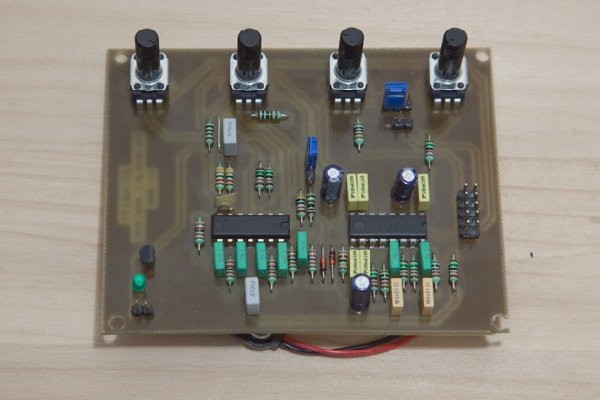
Hi can anyone tell me what these potentiometers on Rob's board is called? I often need ones this size!
And can anyone explain the 10 pin connector for the jumper if I wanted to make one myself?
_________________
www.dogenigt.com
Everything should be made as simple as possible, but no simpler. - Albert Einstein |
|
|
Back to top
|
|
|
LFLab
Joined: Dec 17, 2009
Posts: 497
Location: Rosmalen, Netherlands
|
| Posted: Sun Jun 02, 2013 1:43 am Post subject:
|
|
|
Those are 9mm pots, several manufacturers make them, Alpha too.
Just need to specify that you want vertical mount. |
|
|
Back to top
|
|
|
boundlessFX
Joined: Jun 06, 2013
Posts: 4
Location: JP, MA
|
| Posted: Tue Jun 11, 2013 12:20 am Post subject:
n00b question |
|
|
| What exactly are the components labeled "HDR_3"? I recognize everything else and have most of it on hand, but I've never seen these before. Are they some type of transistor? |
|
|
Back to top
|
|
|
inlifeindeath
Joined: Apr 02, 2010
Posts: 316
Location: Albuquerque, NM
|
|
|
Back to top
|
|
|
boundlessFX
Joined: Jun 06, 2013
Posts: 4
Location: JP, MA
|
| Posted: Wed Jun 12, 2013 6:50 pm Post subject:
|
|
|
| Awesome. Thanks! |
|
|
Back to top
|
|
|
jmejia
Joined: Mar 12, 2009
Posts: 114
Location: portland
|
| Posted: Wed Jul 10, 2013 3:15 pm Post subject:
|
|
|
| Could someone describe what this circuit does? I'm having trouble finding a good description anywhere. I found a video - but it doesn't go into much detail... |
|
|
Back to top
|
|
|
inlifeindeath
Joined: Apr 02, 2010
Posts: 316
Location: Albuquerque, NM
|
|
|
Back to top
|
|
|
jmejia
Joined: Mar 12, 2009
Posts: 114
Location: portland
|
| Posted: Thu Jul 11, 2013 8:37 am Post subject:
|
|
|
| I know it's a delay circuit, I'm familiar with the pt2399. I was assuming this does more or is interesting or different than the other 2399 schematics floating around...? |
|
|
Back to top
|
|
|
robboten
Joined: Nov 26, 2009
Posts: 36
Location: stockholm, sweden
|
| Posted: Tue Aug 13, 2013 10:30 am Post subject:
|
|
|
Hows the new board layout coming along. Am curious and have a couple of 2399 laying here waiting... 
And also... was the "old" pcb layout with pots but without components ever released? |
|
|
Back to top
|
|
|
SteveBull
Joined: Nov 14, 2009
Posts: 4
Location: New York CIty
|
Posted: Sun Nov 30, 2014 7:38 pm Post subject:
power requirements of Zeitgeist and Benjolin
Subject description: what are the specifications |
|
|
I've built both the Zeitgeist and Benjolin at a Harvestworks workshop years ago and now I want to fire them up again - - but I can not find the power supply. Please remind of the circuit specifications. It looks like the Benjolin wants two: v+ and a v- DC referenced to a common ground and the Zeitgeist only one v+ DC to ground. I see I have a 5 pin female DIN power connector on my chassis converted from a Sears/Craftsman tool case.
Thanks,
Steve |
|
|
Back to top
|
|
|
tokyomatik
Joined: Jan 20, 2011
Posts: 171
Location: berlin
Audio files: 6
|
| Posted: Tue Apr 21, 2015 3:17 am Post subject:
|
|
|
| ehm.....anybody has the pnp transfer file for the pcb on the first post here?? |
|
|
Back to top
|
|
|
tokyomatik
Joined: Jan 20, 2011
Posts: 171
Location: berlin
Audio files: 6
|
| Posted: Tue Apr 21, 2015 3:23 am Post subject:
Re: Zeitgeist Schematics |
|
|
| electri-fire wrote: | I asked for the Zeitgeist schematics, but....
Edit: I just remembered Rob mailed them to me. As he also posted the Benjolin schematics I presume he won't mind me posting the Zeitgeist. |
sorry to push again, but if Rob sent u the files to build your own Zeitgeist....why u posted only schematics and parts placement and no layout for pnp transfer??...It's like an invitation for dinner with no food on the table....  |
|
|
Back to top
|
|
|
fluxmonkey
Joined: Jun 24, 2005
Posts: 708
Location: cleve
|
| Posted: Tue Apr 21, 2015 10:02 am Post subject:
Re: Zeitgeist Schematics |
|
|
| tokyomatik wrote: | | electri-fire wrote: | I asked for the Zeitgeist schematics, but....
Edit: I just remembered Rob mailed them to me. As he also posted the Benjolin schematics I presume he won't mind me posting the Zeitgeist. |
sorry to push again, but if Rob sent u the files to build your own Zeitgeist....why u posted only schematics and parts placement and no layout for pnp transfer??...It's like an invitation for dinner with no food on the table.... |
it's not hard to edit the posted jpg to remove the parts outline and leave just the copper. this is DIY, afterall 
b
_________________
www.fluxmonkey.com |
|
|
Back to top
|
|
|
tokyomatik
Joined: Jan 20, 2011
Posts: 171
Location: berlin
Audio files: 6
|
| Posted: Thu May 07, 2015 5:33 pm Post subject:
|
|
|
I'm checking the board with the components and I have some questions:
what are the pots function names?? (from left to right)
the CV input is to control the delay time?
what is SENSOR doing?(HDR 10)
what are the functions of JUMPER and the two HDR 3? jumpers for a different settings ?
the JUMPER next to the led says + and -, should I consider - as Ground??
I will try to etch this board in these days, not so many parts and looks also an easy build...any recomendation? |
|
|
Back to top
|
|
|
tokyomatik
Joined: Jan 20, 2011
Posts: 171
Location: berlin
Audio files: 6
|
| Posted: Sat May 16, 2015 6:49 am Post subject:
|
|
|
Anybody there??
Were my questions too stupid to answer??  |
|
|
Back to top
|
|
|
|

 Forum index » DIY Hardware and Software » Rob Hordijk DIY Designs
