| Author |
Message |
Inventor
Stream Operator

Joined: Oct 13, 2007
Posts: 6221
Location: near Austin, Tx, USA
Audio files: 267
|
 Posted: Tue May 18, 2010 2:59 am Post subject:
Credit Card Synth Posted: Tue May 18, 2010 2:59 am Post subject:
Credit Card Synth
Subject description: BS and KS on a small PCB |
  |
|
I've been breadboarding some BS and KS circuits lately and I've come up with some minimal circuit implementations that would actually fit on a credit card-sized synth.
This would be an analog implementation. I realize that it could be done in digital using just a PIC and some small external circuitry, so it is not the smallest possible circuit, but it is small for a thru-hole analog version.
Part of the space savings comes from elimination of the LM13700 OTA chip and asosciated discretes, the use of thumbwheel pots, and a fixed song played by the BS circuit. Biased up properly, the whole thing can be run from either a 9V battery or a few 1.5V batteries, or even a solar cell. The output would be an 1/8" jack for output to headphones, computer, or with the right cable/adapter, to a mixer.
I wonder if I should work on such a circuit. Comments?
Les
_________________
"Let's make noise for peace." - Kijjaz |
|
|
Back to top
|
|
 |
Dan Lavin
Joined: Nov 09, 2006
Posts: 649
Location: Spring Lake, Mi, USA
Audio files: 21
|
| Posted: Tue May 18, 2010 5:41 am Post subject:
|
|
|
Les, as long as you're not diluting your current project /developments, I'd say go for it. Although someone (me, for instance), might not have an application for it, it could encourage further experimentation or inspire another light bulb moment for you or someone else on the forum.
_________________
Synth DIY since 1977! |
|
|
Back to top
|
|
|
Inventor
Stream Operator
Joined: Oct 13, 2007
Posts: 6221
Location: near Austin, Tx, USA
Audio files: 267
|
| Posted: Tue May 18, 2010 7:18 am Post subject:
|
|
|
OK, Dan, I'm actually waiting on others right now for continuation of the KS project and the BS project is awaiting further input from others as well, so I guess I can do this without affecting schedule of BS or KS modular boards.
The block diagram of the circuit that I'm working with goes like this:
555 => 4040 => LogicIC => 555 => BL3102 => BL3207 => opamp => 1/8" jack
with a feedback path from the opamp through a passive RC back to the BL3207. Also there is a small handful of discretes including some thumbwheel pots, R's and C's.
That's all there is to it, 7 chips with most of them being 8 pin DIPs. Actually the first 555 can be eliminated if a 4060 is used instead of a 4040, and the Logic IC can be replaced with resistors if desired, so that reduces the circuit to just 5 chips. Furthermore, only the last 4 chips are required for the KS part of the circuit so that if someone wanted to add KS to say a Lunetta circuit, it would only require 4 8-pin chips.
I'll make time to draw up a schematic later today or tomorrow (or I'll try to anyway).
Les
_________________
"Let's make noise for peace." - Kijjaz |
|
|
Back to top
|
|
|
Inventor
Stream Operator
Joined: Oct 13, 2007
Posts: 6221
Location: near Austin, Tx, USA
Audio files: 267
|
|
|
Back to top
|
|
|
Dan Lavin
Joined: Nov 09, 2006
Posts: 649
Location: Spring Lake, Mi, USA
Audio files: 21
|
| Posted: Tue May 18, 2010 10:46 am Post subject:
|
|
|
Hmmmmm.......
So the delay time could be a function of the sequence? That may create some interesting efffects. Or am I reading more into this than you intend?
_________________
Synth DIY since 1977! |
|
|
Back to top
|
|
|
Inventor
Stream Operator
Joined: Oct 13, 2007
Posts: 6221
Location: near Austin, Tx, USA
Audio files: 267
|
| Posted: Tue May 18, 2010 11:40 am Post subject:
|
|
|
| Dan Lavin wrote: | Hmmmmm.......
So the delay time could be a function of the sequence? That may create some interesting efffects. Or am I reading more into this than you intend? |
Yes. One simplification is that the filter is not a function of the sequence - it just has a pot to adjust it, however the delay chip (BBD) has a delay that is a function of the sequence (and possibly a pot).
The four pots shown are: tempo, filter, feedback, and volume. Actually now that I think of it i should add a delay pot as well, so five pots.
I'm thinking there should be a small solderable patch panel for the sequence so people can set whatever sequence they want or use multiple cards for multiple voices of sound.
Les
_________________
"Let's make noise for peace." - Kijjaz |
|
|
Back to top
|
|
|
Sound
Joined: Jun 06, 2006
Posts: 842
Audio files: 1
|
| Posted: Tue May 18, 2010 3:56 pm Post subject:
|
|
|
| Hi Les, I dont understand very well this project, so my first question is: will content this card synth the software of the Boolean Sequencer? |
|
|
Back to top
|
|
|
Inventor
Stream Operator
Joined: Oct 13, 2007
Posts: 6221
Location: near Austin, Tx, USA
Audio files: 267
|
| Posted: Tue May 18, 2010 4:48 pm Post subject:
|
|
|
| Sound wrote: | | Hi Les, I dont understand very well this project, so my first question is: will content this card synth the software of the Boolean Sequencer? |
Yes Sound, if I understand the question properly, this card will contain a simplified boolean sequencer consisting of two chips, similar to some of the software BS programs that I have shared in the past.
Les
_________________
"Let's make noise for peace." - Kijjaz |
|
|
Back to top
|
|
|
droffset

Joined: Feb 02, 2009
Posts: 515
Location: London area
Audio files: 2
|
|
|
Back to top
|
|
|
Inventor
Stream Operator
Joined: Oct 13, 2007
Posts: 6221
Location: near Austin, Tx, USA
Audio files: 267
|
| Posted: Tue May 18, 2010 7:36 pm Post subject:
|
|
|
| droffset wrote: | Sorry for being ignorant, but what are the functions of BL3102 and BL3207?
Good choice on 4060, I think this IC is going to be great for small portable thingies. |
droffset, together the BL2102 and BL3207 form an analog delay line suitable for use in various circuits including Lunettas. The BL3102 is the support chip that has a three-inverter oscillator, a Vgg reference voltage generator, and a toggle flip-flop that creates the required two clock phases CP1 and CP2.
The BL3207 chip has a 1024 stage bucket-brigade device (BBD) delay line that works kind of like a line of firefighters passing buckets of water along in a line to put out a fire, only the buckets are teeny capacitors and the firefighters are teeny transistor circuits.
When the two-phase digital clock and reference voltage are applied to the BBD chip, a digitally clocked analog delay effect is produced. Some other characteristics are that some external resistors and capacitors are required to bias up the input signal and combine the dual output signals into one, with DC blocking on both input and output.
The pair of chips plus discretes forms a simple delay line that is useful for audio effects like flanger, echo, etc., and it works great in Karplus Strong. Oh, and it generates some high frequency clock spikes on the output so it is necessary to add filtering (which I have not completely figured out yet).
Les
_________________
"Let's make noise for peace." - Kijjaz |
|
|
Back to top
|
|
|
Inventor
Stream Operator
Joined: Oct 13, 2007
Posts: 6221
Location: near Austin, Tx, USA
Audio files: 267
|
|
|
Back to top
|
|
|
droffset
Joined: Feb 02, 2009
Posts: 515
Location: London area
Audio files: 2
|
| Posted: Tue May 18, 2010 8:17 pm Post subject:
|
|
|
Cool I'm starting to listen to it.
So it's like an analog shift register, and it's there to add some reverb?
EDIT
Does it act like a VCA to control decay times?
How is the tomtom sounding one different from the guitar one, which sounds more distorted and complex? Is there filering going on too?
_________________
==================
Check out the FREE Intro to Lunettas Document
https://docs.google.com/document/d/1V9qerry_PsXTZqt_UDx7C-wcuMe_6_gyy6M_MyAgQoA/edit?usp=sharing
Edit: Spelling mistakes. |
|
|
Back to top
|
|
|
Inventor
Stream Operator
Joined: Oct 13, 2007
Posts: 6221
Location: near Austin, Tx, USA
Audio files: 267
|
| Posted: Tue May 18, 2010 9:05 pm Post subject:
|
|
|
droffset, here is the wikipedia page on Karplus Strong:
http://en.wikipedia.org/wiki/Karplus-Strong_string_synthesis
The first illustration shows a block diagram of the KS circuit, which is a feedback loop with a summing amp, a delay line and a filter. You apply a stim pulse and round and round the signal goes, making a percussion or guitar-ish sound. By varying the filter and delay line and loop gain of the summing amp, we can adjust the sound.
Generally longer delays and lower frequency cutoff of the filter create more string-like sounds and shorter delays with higher frequencies create more percussive sounds. Also if you turn up the loop gain you get loud sounds such as what you can hear in the show from time to time.
I think it's an amazing algorithm and it really makes a lot of great sounds with lots of possibilities. Thank you Karplus and Strong!
Les
_________________
"Let's make noise for peace." - Kijjaz |
|
|
Back to top
|
|
|
Inventor
Stream Operator
Joined: Oct 13, 2007
Posts: 6221
Location: near Austin, Tx, USA
Audio files: 267
|
| Posted: Wed May 19, 2010 6:17 am Post subject:
|
|
|
This morning I got up early and completed the schematic capture and layout of the credit card synth, attached. It routes well and all the circuitry fits on the board without much room to spare.
I'm not completely sure if the schematic is 100% correct in that I have not breadboarded this exact circuit yet. I'll order parts this week so I can build the breadboard next week. Also I would like to add some sort of compression so that loud feedback squeals do not blast our ears as on the current design.
Les
| Description: |
| Credit Card Synth Schematic |
|

Download (listen) |
| Filename: |
CCS1sch.pdf |
| Filesize: |
21.86 KB |
| Downloaded: |
853 Time(s) |
| Description: |
|
Download (listen) |
| Filename: |
CCS1pcb.pdf |
| Filesize: |
23.34 KB |
| Downloaded: |
711 Time(s) |
_________________
"Let's make noise for peace." - Kijjaz |
|
|
Back to top
|
|
|
electri-fire
Joined: Jul 26, 2006
Posts: 536
Location: Dordrecht NL
Audio files: 4
G2 patch files: 4
|
| Posted: Wed May 19, 2010 10:36 am Post subject:
|
|
|
| Inventor wrote: | | If you turn up the loop gain you get loud sounds such as what you can hear in the show from time to time. |
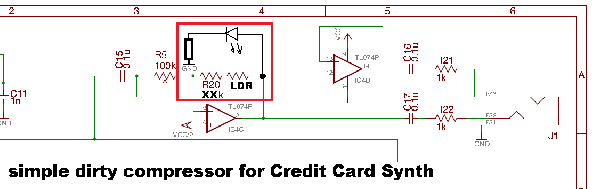
It got way loud, but it was a cool sound. So an onboard compressor limiter would be nice. It needn'd be all that sofisticated, I think the creditcard size would be a nice concept to adhere to. So I suggest an optical compressor implemented at the final opamp. With a DIY vactrol, the output driving an LED, have an LDR as the feedback resistor to reduce gain with too loud signals.
from the LDR Wiki: A photoresistor or light dependent resistor or cadmium sulfide (CdS) cell is a resistor whose resistance decreases with increasing incident light intensity. It can also be referred to as a photoconductor. |
|
|
Back to top
|
|
|
electri-fire
Joined: Jul 26, 2006
Posts: 536
Location: Dordrecht NL
Audio files: 4
G2 patch files: 4
|
| Posted: Wed May 19, 2010 1:15 pm Post subject:
|
|
|
| Inventor wrote: | | Together the BL2102 and BL3207 form an analog delay line suitable for use in various circuits including Lunettas. |
| Description: |
|
Download (listen) |
| Filename: |
MN3207 BBD for Analog Signal Delays.pdf |
| Filesize: |
245.42 KB |
| Downloaded: |
630 Time(s) |
| Description: |
|
Download (listen) |
| Filename: |
BL3102 - COMS Clock Generator-Driver For Low Voltage Operation BBD.pdf |
| Filesize: |
25 KB |
| Downloaded: |
1307 Time(s) |
|
|
|
Back to top
|
|
|
electri-fire
Joined: Jul 26, 2006
Posts: 536
Location: Dordrecht NL
Audio files: 4
G2 patch files: 4
|
|
|
Back to top
|
|
|
Inventor
Stream Operator
Joined: Oct 13, 2007
Posts: 6221
Location: near Austin, Tx, USA
Audio files: 267
|
| Posted: Wed May 19, 2010 2:08 pm Post subject:
|
|
|
Yes, Mathe, I got what you meant from your previous description. Sounds like a cool idea but there are some mechanical issues. It requires hand assembly and bending of wires and heat shrink or other optical isolation. It's a cool way to go for onesie-twosies, but I tend to design for production.
I was thinking of a diode and resistor in feedback or something, not sure... Or a clamp at the bias of the MN3207, that would do it, just like on the modular KS board.
Well, more thought is needed and we can use such a circuit in our workshop, but for this board I'm not sure if it will be appropriate. Please do keep those ideas flowing, though, my friend!
Les
_________________
"Let's make noise for peace." - Kijjaz |
|
|
Back to top
|
|
|
Sound
Joined: Jun 06, 2006
Posts: 842
Audio files: 1
|
|
|
Back to top
|
|
|
Sound
Joined: Jun 06, 2006
Posts: 842
Audio files: 1
|
| Posted: Thu May 20, 2010 8:46 am Post subject:
|
|
|
OK,
Which are the prefixes of 4070N and 4060 ? HEF4070BP, 74HC4060N?
Where I can found BL2102 and BL3207?
 |
|
|
Back to top
|
|
|
Inventor
Stream Operator
Joined: Oct 13, 2007
Posts: 6221
Location: near Austin, Tx, USA
Audio files: 267
|
| Posted: Thu May 20, 2010 8:48 am Post subject:
|
|
|
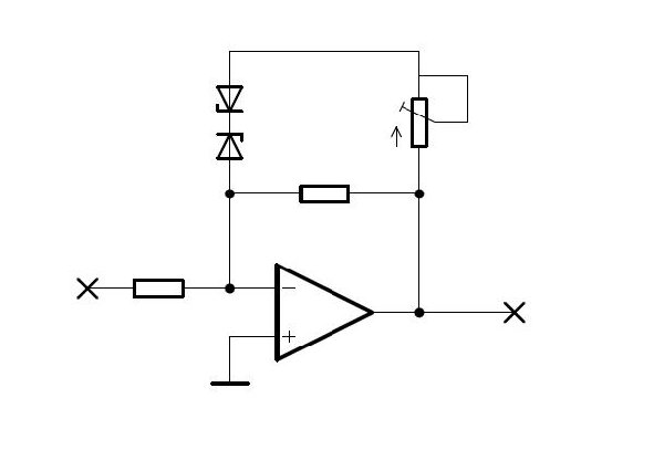
Yes Sound, that is very similar to what I was thinking. With a zener diode implementation you would connect the two diodes in series, and with a diode or LED implementation you would connect the two diodes in parallel. I don't have much of an idea what the resistor value should be.
Les
_________________
"Let's make noise for peace." - Kijjaz |
|
|
Back to top
|
|
|
Sound
Joined: Jun 06, 2006
Posts: 842
Audio files: 1
|
| Posted: Thu May 20, 2010 8:49 am Post subject:
|
|
|
| electri-fire wrote: | | Les, you already had an idea about a compressor , but this is what I meant. It may change the sound as well, clipping the signal asymmetrically with loud sounds. I tend to quite like that usually. |
BTW looks very interesting... I would try achieve a Vactrol or a DIY Vactrol |
|
|
Back to top
|
|
|
Inventor
Stream Operator
Joined: Oct 13, 2007
Posts: 6221
Location: near Austin, Tx, USA
Audio files: 267
|
| Posted: Thu May 20, 2010 8:50 am Post subject:
|
|
|
| Sound wrote: | OK,
Which are the prefixes of 4070N and 4060 ? HEF4070BP, 74HC4060N?
Where I can found BL2102 and BL3207?
|
Sound, the Chips are CD4060 and CD4070 devices. The BL3102 (sorry for correction, it is BL3102 not BL2102) and BL3207 are available from smallbear.
Les
_________________
"Let's make noise for peace." - Kijjaz |
|
|
Back to top
|
|
|
Sound
Joined: Jun 06, 2006
Posts: 842
Audio files: 1
|
| Posted: Thu May 20, 2010 8:52 am Post subject:
|
|
|
| Inventor wrote: | I don't have much of an idea what the resistor value should be.
Les |
I was trying with 100K pot and was something within, should be experimented with the synth card I think.
EDIT: In any case in the Zener example, all wave over the Zener threshold will have gain Rf/Rin where Rf is the two feedback resistors in parallel. I think. |
|
|
Back to top
|
|
|
electri-fire
Joined: Jul 26, 2006
Posts: 536
Location: Dordrecht NL
Audio files: 4
G2 patch files: 4
|
| Posted: Thu May 20, 2010 10:19 am Post subject:
|
|
|
| Sound wrote: | | Which are the prefixes of 4070N and 4060 ? HEF4070BP, 74HC4060N? |
The prefixes aren't all that important, CD, HEF, 74xx series, no matter. Some may be "high speed" or "low power" etc. but they should all work.
Edit; oops, too late. I should have refreshed the page before answering. |
|
|
Back to top
|
|
|
|

 Forum index » DIY Hardware and Software » Les Hall's Projects including eChucK