| Author |
Message |
LektroiD

Joined: Aug 23, 2008
Posts: 1019
Location: Scottish Borders
Audio files: 2
G2 patch files: 2
|
|
|
Back to top
|
|
 |
isak

Joined: Dec 13, 2009
Posts: 847
Location: Israel
Audio files: 18
|
 Posted: Sun Jan 10, 2010 4:44 am Post subject: Posted: Sun Jan 10, 2010 4:44 am Post subject:
|
  |
|
Uncle K can u please upload a biger pic of the strip board ?
thanks 
_________________
http://www.myspace.com/mgmtrance |
|
|
Back to top
|
|
|
jimh54
Joined: Apr 11, 2004
Posts: 6
|
|
|
Back to top
|
|
|
Uncle Krunkus
Moderator

Joined: Jul 11, 2005
Posts: 4761
Location: Sydney, Australia
Audio files: 52
G2 patch files: 1
|
| Posted: Mon Aug 16, 2010 5:10 pm Post subject:
|
|
|
Good on ya jimh54! 
I haven't re-installed Lochmaster yet, so I can't look at it, but I will soon.
Is it done in the newer Lochmaster version?
If so, I don't think I'll be able to open it anyway.
On that point, it would be good if you can do a .jpg of both sides and post those so people can still use it even if they don't have Lochmaster. Let me know if you don't know how to do that and I'll give you a hand.
I've been thinking of doing exactly this for a long time, (but I don't have time!) I'd like to update my original SoundLab to the Ultimate and make it a matrix patch version, a bit like an AKS without the joystick.
_________________
What makes a space ours, is what we put there, and what we do there. |
|
|
Back to top
|
|
|
jimh54
Joined: Apr 11, 2004
Posts: 6
|
| Posted: Tue Aug 17, 2010 9:08 am Post subject:
RE: Soundlab+ |
|
|
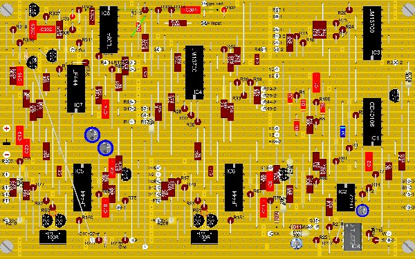
Uncle,
Yes, it's in Soundlab 3.0. Here are the .jpg versions.
I'm sure your version will be much better than mine. You have more experience and know where to move stuff around to give more room. I look forward to seeing it.
| Description: |
|
| Filesize: |
1013.34 KB |
| Viewed: |
3581 Time(s) |
| This image has been reduced to fit the page. Click on it to enlarge. |
|
| Description: |
|
| Filesize: |
1.18 MB |
| Viewed: |
3084 Time(s) |
| This image has been reduced to fit the page. Click on it to enlarge. |

|
|
|
|
Back to top
|
|
|
Uncle Krunkus
Moderator
Joined: Jul 11, 2005
Posts: 4761
Location: Sydney, Australia
Audio files: 52
G2 patch files: 1
|
| Posted: Tue Aug 17, 2010 2:35 pm Post subject:
|
|
|
It looks great, but, like I thought, it's in 3.0, I can only open 2.0 files. The best thing is that you've posted the .jpg, so version problems don't matter.
_________________
What makes a space ours, is what we put there, and what we do there. |
|
|
Back to top
|
|
|
adambee7
Joined: Apr 04, 2009
Posts: 420
Location: united kingdom
|
| Posted: Mon Sep 06, 2010 12:14 am Post subject:
|
|
|
| The sample and hold has been updated. R16 has been removed, R7 has been removed and D1 has been replaced with a 100K resistor. The project should be up at MFOS. |
|
|
Back to top
|
|
|
adambee7
Joined: Apr 04, 2009
Posts: 420
Location: united kingdom
|
| Posted: Tue Sep 07, 2010 1:45 am Post subject:
|
|
|
| adambee7 wrote: | | The sample and hold has been updated. R16 has been removed, R7 has been removed and D1 has been replaced with a 100K resistor. The project should be up at MFOS. |
Sorry thats R316, R307 to be removed and D301 replaced with a 100K resistor. |
|
|
Back to top
|
|
|
meanfuzz
Joined: Jan 05, 2012
Posts: 2
Location: Italy
|
| Posted: Thu Jan 05, 2012 11:15 am Post subject:
|
|
|
| Hello, I am a newbie here and pretty much a rookie in diy electronics, too - just built a few effect stompboxes and a WSG. So maybe this is a naive question, but it is driving me mad: what do FT1 and FT2 stand for in the stripboards posted up here? What should I connect those pins to? Thanks a lot in advance. |
|
|
Back to top
|
|
|
meanfuzz
Joined: Jan 05, 2012
Posts: 2
Location: Italy
|
| Posted: Fri Jan 06, 2012 4:25 am Post subject:
|
|
|
| Duh! Although I thought I had read the whole thread carefully, I overlooked something... Exactly the anwer I was looking for. |
|
|
Back to top
|
|
|
elmegil

Joined: Mar 20, 2012
Posts: 2179
Location: Chicago
Audio files: 16
|
| Posted: Sat Nov 03, 2012 7:34 pm Post subject:
|
|
|
| Arg, I now have a jones for one of these (building one on PCB for someone else will do that to ya) but I don't have any 62 wide stripboards! |
|
|
Back to top
|
|
|
VanaVara
Joined: Jan 30, 2012
Posts: 23
Location: Vilnius
|
| Posted: Mon Nov 12, 2012 5:30 pm Post subject:
|
|
|
Hi guys! I'm building this SoundLab 1.1 (from Uncle stripboard in Lochmaster file) and i found myself totaly lost with wiring the panel --- i need your HELP! 
I was wiring pots and switches looking at Uncle stripboard (for example R48-1, R48-2) and also looking at Ray's original wiring panel scheme, where on pots there are rectangles with letters (PP, RR and so on...) and i thought i'm doing fine but then i've found for example pot R19 --- on striboard there's ONLY ONE referance R19-2, BUT on Rays layout i see 3 possible connections (PP, RR, QQ) and i don't know what to to??? Also the numeration --- for example R44 --- i see A, B and C connections but is R44-1 leftside tip or the rightside tip (in other words does R44-1 goes to A or C?)
Guys, i would really appreciate your help, because i've spent so many hours sordering this Devil and now i dont wanna let it down... 
Thank you in advance |
|
|
Back to top
|
|
|
elmegil
Joined: Mar 20, 2012
Posts: 2179
Location: Chicago
Audio files: 16
|
| Posted: Mon Nov 12, 2012 11:19 pm Post subject:
|
|
|
Each pot has three pins numbered 1, 2, and 3. So R19-2 means the middle pin (the easiest one to spot ). So R19-2 can only be RR. PP and QQ are positive and negative supplies respectively.
For R44, if you compare the wiring diagram with the PCB layout, the PCB layout actually identifies any locations that are not common things like supply or ground. So for A B & C, you can look and see that A is R44-1, B is R44-2, and C is ground. That should also help because all the pots will be numbered the same way; looking from the rear, as the wiring diagram shows, you have pin 1 on the left and pin 3 on the right.
Hopefully this will help you sort it out |
|
|
Back to top
|
|
|
Uncle Krunkus
Moderator
Joined: Jul 11, 2005
Posts: 4761
Location: Sydney, Australia
Audio files: 52
G2 patch files: 1
|
| Posted: Tue Nov 13, 2012 4:46 am Post subject:
|
|
|
I wanted to apologise for my tardyness in helping people build this stripboard (or the WSG for that matter). It's almost 7 years since this thread started, and the layout was done at least a year before that. My head just can't keep hold of all this stuff I used to know.
I do remember the idea of doing the Soundlab on a stripboard seemed crazy then. Probably still does to most. 
So,.......
Attempt to build this stripboard Soundlab at your own peril!! 
You will need a lot of stripboard experience.
You will need troubleshooting skills, 
an eye for detail, 
and patience. 
_________________
What makes a space ours, is what we put there, and what we do there. |
|
|
Back to top
|
|
|
elmegil
Joined: Mar 20, 2012
Posts: 2179
Location: Chicago
Audio files: 16
|
| Posted: Tue Nov 13, 2012 5:37 am Post subject:
|
|
|
 |
|
|
Back to top
|
|
|
Uncle Krunkus
Moderator
Joined: Jul 11, 2005
Posts: 4761
Location: Sydney, Australia
Audio files: 52
G2 patch files: 1
|
| Posted: Tue Nov 13, 2012 5:59 am Post subject:
|
|
|
And I can't just go back to studying these older projects, when I've got so many other projects that need to be worked on right now!!! 
Maybe I have an attention deficit or something!
_________________
What makes a space ours, is what we put there, and what we do there. |
|
|
Back to top
|
|
|
elmegil
Joined: Mar 20, 2012
Posts: 2179
Location: Chicago
Audio files: 16
|
| Posted: Tue Nov 13, 2012 6:00 am Post subject:
|
|
|
| I expect to build this by the end of the year, so I'll be happy to take on that knowledge |
|
|
Back to top
|
|
|
VanaVara
Joined: Jan 30, 2012
Posts: 23
Location: Vilnius
|
| Posted: Tue Nov 13, 2012 4:55 pm Post subject:
|
|
|
Thanx again for your help!
Haha, if i knew how many patience, soldering and madness this project would take i'd never start it at the first place... 
Anyway, i can almost see a light in the end of the tunnel, however i dont know if i correctly wired all pots and switches, it's almost 2am and my table is fully covered with "spaghetti" and i think i'll try to finish this stuff in the morning..... and i have one final noob question: where do "positive" and "negative" wires from STRIPBOARD go to...? Positive and negative wires from the batteries go to Power switch --- OK, Ground goes to R27 and so on --- OK, but where should i connect (+) and (-) from stripboard? To R19 [PP] and [QQ]? http://www.musicfromouterspace.com/analogsynth_new/SOUNDLABMINISYNTH/images/soundlab2007panelwiringwlabels2.gif
Well anyway i'll try this in in the morning but it would be great to be sure...  |
|
|
Back to top
|
|
|
VanaVara
Joined: Jan 30, 2012
Posts: 23
Location: Vilnius
|
| Posted: Wed Nov 14, 2012 4:48 am Post subject:
|
|
|
So i have finished SoundLab and it's not working, i only can hear faint hiss sound.....
Maybe someone can help me work out what is wrong?
First of all, where should i connect (+) and (-) wires from the stripboard, i have tried connecting them to R19, and also to Main Power switch and nothing happens, only this hissing sound. Maybe there are some other critical parts i should check out? I'm totaly lost and confused  |
|
|
Back to top
|
|
|
elmegil
Joined: Mar 20, 2012
Posts: 2179
Location: Chicago
Audio files: 16
|
| Posted: Wed Nov 14, 2012 5:05 am Post subject:
|
|
|
When testing make sure the main, VCA and VCF frequency pots are turned all the way up. Then turn up the mix knob for each oscillator in turn.
I am out of town, and have not started on making this stripboard, so I can't give you a lot of guidance for that sort of thing; I would assume the + and - connections are the ones that go to the red and black wires to the panel, for the pots that get wired to +9V or -9V. But not having done it, and not having the time right now to go analyze it, I can't say for certain.
I do have the large enough stripboards now, and like I said, I plan to build this soon, but not yet.... |
|
|
Back to top
|
|
|
prgdeltablues
Joined: Sep 25, 2006
Posts: 222
Location: UK
Audio files: 12
|
| Posted: Wed Nov 14, 2012 6:17 am Post subject:
|
|
|
The point marked + on the stripboard layout needs to be connected to the positive output from your main switch (that is, the point labelled +9v on the power supply section of the schematic on the MFOS site, and PP on the panel wiring diagram). Likewise, the point marked - is connected to the -9V connection on the switch, QQ on the panel wiring. And the point in between on the stripboard, labelled with a sideways T symbol is the connection for Ground 'C' on the panel wiring diagram - it is unlikely to work without that being connected. It sounds as if you may not have connected the Ground to the stripboard.
hope this helps
Peter |
|
|
Back to top
|
|
|
elmegil
Joined: Mar 20, 2012
Posts: 2179
Location: Chicago
Audio files: 16
|
| Posted: Sat Dec 08, 2012 7:22 pm Post subject:
|
|
|
Now I've had time to finish the other soundlab I was working on, and looked through the SLMS+ schematics and things on Ray's site and these stripboards, I rescind my claim that I was going to do this stripboard (even the second version)
I want the capabilities of the Micro Sample & Hold, not the original (presumably) single chip TL084 based S&H. I'm going to be patching this out like I did for the other soundlab as well.
I'm not any good at all with creating stripboard circuits, so I am going to think about how I plan to do this. It's very likely I will just order the two PCB set from Ray and have done. |
|
|
Back to top
|
|
|
Starspawn
Joined: Jun 14, 2013
Posts: 85
Location: Oslo
|
| Posted: Fri Mar 27, 2015 10:56 am Post subject:
|
|
|
Ive made the soundlab+ stripboard version succesfully.
Sadly although the krunkus stuff is all correct, most of the mods to SL+ posted here had problems from missing the output of noise altogether, to no cuts under inverter opamp and a few more.
Id correct them all but dont have the file.
I do have one problem, but I have a hunch thats due to how Ive patched it and attenuated CV. The VCA doesnt go to silent, is that perhaps since Im using attenuators in front of the input resistors for VCA CV?
Worth mentioning its on +/- 12V as well (together with a 1 bus keyboard and a adsr circuit) |
|
|
Back to top
|
|
|
Uncle Krunkus
Moderator
Joined: Jul 11, 2005
Posts: 4761
Location: Sydney, Australia
Audio files: 52
G2 patch files: 1
|
| Posted: Fri Mar 27, 2015 2:50 pm Post subject:
|
|
|
Remember that the more you load the power supply, the more the whole setup becomes susceptible to crosstalk. Make sure the supply can deliver at least 15-20% more current than you "need". Otherwise you'll get ripples in the supply (say from the VCOs) contaminating everything else, and vice versa.
_________________
What makes a space ours, is what we put there, and what we do there. |
|
|
Back to top
|
|
|
Starspawn
Joined: Jun 14, 2013
Posts: 85
Location: Oslo
|
| Posted: Fri Mar 27, 2015 3:19 pm Post subject:
|
|
|
Yeah, I use a doepfer supply for their minicase in this so should be more than enough for only those three modules (ADSR is yusynth, so 10ma only).
It seems to me that when using 12V both the filter and the amp is dependent on the AD generator for their basic levels ... ie the filter reaches zero only on a highish AD setting, and VCA does not at all, so Im thinking the resistors at the CV inputs might need tweaking?
Or the added 27K in SL+ from V- to CV input for VCF and VCA?
(I have AD out wired directly to 4 pots each having ground on pin one, AD on three and out on 2)
I noticed that with the VCOs as well when I had to small resistor on one of the CV inputs there, but with stock both have a good range.
Looks like so, Ill do interior pics a little later

 |
|
|
Back to top
|
|
|
|

 Forum index » DIY Hardware and Software » MusicFromOuterSpace.com designs by Ray Wilson
