| Author |
Message |
john trials
Joined: May 12, 2020
Posts: 14
Location: CT
|
 Posted: Tue May 12, 2020 6:53 pm Post subject:
LFO Controller - Is this normal behavior? Posted: Tue May 12, 2020 6:53 pm Post subject:
LFO Controller - Is this normal behavior?
Subject description: sine, triangle and square all output DC voltage when gate=0v in gate mode |
  |
|
My LFO Controller works great, except when in "gate mode" and no key is depressed.
When the gate=0 volts (no keys depressed), the sine and triangle outputs go to +5 volts DC, and the square output goes to -5 volts DC. The Control output goes to ground as expected. The sine, triangle, and square waves are perfect (10v p-p) when a key is depressed, and the gate and trigger outputs operate as expected.
Is this normal? I would expect all outputs to go to ground when no key is depressed.
Is this normal behavior for the LFO Controller? Can someone please test theirs and let me know how it behaves? |
|
|
Back to top
|
|
 |
gabbagabi

Joined: Nov 29, 2008
Posts: 652
Location: Berlin by n8
Audio files: 23
|
|
|
Back to top
|
|
|
john trials
Joined: May 12, 2020
Posts: 14
Location: CT
|
| Posted: Thu May 14, 2020 5:49 am Post subject:
|
|
|
Thanks for the reply, Gabbagabi. I understand most op amp circuits, but am still a bit uncertain regarding op amps being used as comparators (or an "AND" gate, like IC2c). The gate part of that circuit has me a bit baffled.
I find it hard to believe that a DC voltage output would be intentional by design. Maybe this was overlooked, or not realized (but of course there is always the possibility that I wired something incorrectly).
This problem has me completely baffled.
Thomas Henry mentions that pin 7 of IC1b goes to -15v when the oscillations stop (when there is no gate signal and Q1 becomes a short circuit). I have written in my notes that my IC1b pin 7 mainly goes to +15v but sometimes -15v. That is something that I have to examine more. I may have seen one of those voltages when there was a gate signal. |
|
|
Back to top
|
|
|
john trials
Joined: May 12, 2020
Posts: 14
Location: CT
|
| Posted: Thu May 14, 2020 7:03 am Post subject:
|
|
|
On my LFO Controller, in gate mode, with no key pressed, IC1b pin 7 goes to -15v sometimes, and +15v sometimes. That seems by strange, but in the end, both of those voltages produce -15v at IC2c pin 8, so the Square output (J3) always goes to -5v DC when no key is pressed (and the tri and sine outputs, J6 and J7, always go to +5v DC when no key is pressed).
The gate at the 2N5461 operates well, with +15v (key pressed) and GND (no key pressed).
Hopefully this additional info will help someone determine if this circuit is operating according to the design.
Ideally it'd be nice if someone with an LFO Controller could test theirs to see if I am seeing normal behavior, but this circuit doesn't seem to be hugely popular recently. |
|
|
Back to top
|
|
|
gabbagabi
Joined: Nov 29, 2008
Posts: 652
Location: Berlin by n8
Audio files: 23
|
| Posted: Fri May 15, 2020 2:03 am Post subject:
|
|
|
i try to explain it with words
- first, all the circumstances uve described matching perfectly together, exept that " IC1b pin 7 goes to -15v sometimes, and +15v sometimes" it should stay steady at -15v, but let us do ignore it for now as you have stated right u "may have seen one of those voltages when there was a gate signal".
- start with the osc-core, it produces a triangle that goes from 0V to -5V (as stated in the schemo) on pin 1 of IC1 and a square that goes from 15V to -15V pin 7 IC1
if in gate mode and no key is pressed Q1 is shortening the integration cap, the triangle out is at 0V then
- in order to to get a -/+5V triangle (and sinus) the signal from pin 1 of IC1, lets call it raw-tri, gets amplified by two (now it goes from 0V to -10V) and receives an offset of +5V (now it goes from -5V to 5V)
-->those are the 5V ur measuring when no key is pressed (core at 0V)
u would need to change the core if you like to change the behavior
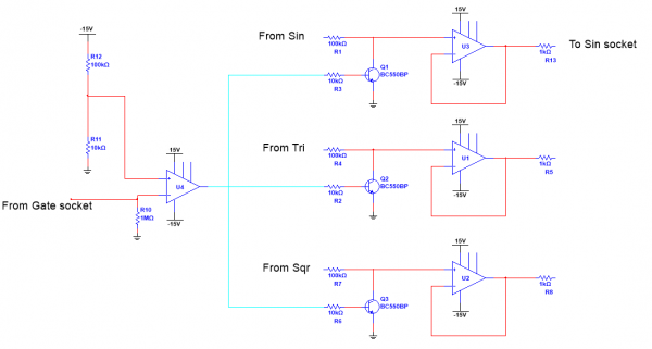
or u could add extra little circuiterry, i can imagine at least 3 ways to silence to wave outs when no gate is present.
The most non-inversive way could be to shorten the outputs to ground.
with the attached idea u would not need to solder around on the board, and you could test it with comfort on a breadboard.
It it just an idea -no guarantee
| Description: |
|
| Filesize: |
24.88 KB |
| Viewed: |
166 Time(s) |
| This image has been reduced to fit the page. Click on it to enlarge. |
|
|
|
|
Back to top
|
|
|
john trials
Joined: May 12, 2020
Posts: 14
Location: CT
|
| Posted: Fri May 15, 2020 5:02 am Post subject:
|
|
|
Gabbagabi: Thank you so much for your ideas. I really appreciate it.
It is very interesting to learn how someone else analyzes that circuit. I was really focused on the pathway along the lower part of sheet 1 (from the triangle oscillator to the square output...especially troubling to me because I am definitely getting random +15v and -15v DC at IC1 pin 7 when the gate goes to ground). I hadn't thought of looking closely at how the triangle signal carries over to sheet 2 of the schematic to help explain what I am seeing.
Your explanation makes a lot of sense. I see that my circuit is probably operating as it was designed (although not as I wished it would). I am a bit surprised that an LFO would be designed to allow a DC voltage output (unless there is some kind of use in a synth for DC coming out of an LFO that I am not aware of). I am surprised that for a design that is 9 years old that I have never read about this strange feature of the LFO Controller design.
I really appreciate that you spent the time to devise a potential solution to the problem, too. I have an electrical engineering degree from the 1980s, but I am probably the worst EE on the planet. My career was spent as a mechanical designer, where I was very capable.
I had been trying to think of a way to block the DC at the sine, triangle and square wave outputs. I had only thought of using capacitors, but that wouldn't work well with an LFO trying to operate at low frequencies. So thank you for your clever design of a transistor switch. I am learning! I will try your add-on circuit soon (first I have to make a guitar stompbox for my son's birthday). |
|
|
Back to top
|
|
|
gabbagabi
Joined: Nov 29, 2008
Posts: 652
Location: Berlin by n8
Audio files: 23
|
| Posted: Sat May 16, 2020 1:02 am Post subject:
|
|
|
Yesterday while brushing my teeth i have recognized that my little circuit idea will certainly NOT work as desired. 
probably it will take the output to 0V while no gate is present.
BUT the moment gate goes high the TRI SIN output immediately goes back to +5V. 
the further i think about, the more i think that the 0V thing doesn´t matter that much, but i would think about to get inverted outs.
lets say u have connected the LFO (tri or sin) to a VCO. If you hit the key, the LFO starts to decrease the frequenzy of the VCO. always.
I can imagine that it would be usefull to have the option that the frequenzy goes up when u hit the key? |
|
|
Back to top
|
|
|
john trials
Joined: May 12, 2020
Posts: 14
Location: CT
|
| Posted: Sat May 16, 2020 4:27 am Post subject:
|
|
|
I will still give some thought to a fix for this. I realized that a repair like gabbagabi's may work in gate mode, but will mess up the trigger mode. I like the circuit and will play with it a bit to learn more. Maybe Thomas Henry left the LFO Controller with the DC outputs because the fix is too complex.
I'd love it if someone who has built one can let me know how theirs operates.
For now, I will add this module to my system, and just avoid the sine, tri, and square outputs when using "gate mode". The "control output" works very well in all modes, and it'll be fun to try the delayed response of this module. |
|
|
Back to top
|
|
|
gabbagabi
Joined: Nov 29, 2008
Posts: 652
Location: Berlin by n8
Audio files: 23
|
| Posted: Sat May 16, 2020 5:15 am Post subject:
|
|
|
no, it would leave the "normal" mode unattached  |
|
|
Back to top
|
|
|
|

 Forum index » DIY Hardware and Software » Thomas Henry designs
