| Author |
Message |
thethinker
Joined: Dec 22, 2024
Posts: 2
Location: USA
|
 Posted: Sun Dec 22, 2024 5:18 pm Post subject:
555 Synth questions and AREG Help Posted: Sun Dec 22, 2024 5:18 pm Post subject:
555 Synth questions and AREG Help
Subject description: My first build, I want to check some stuff |
  |
|
Newb here! I built the noise maker from Forest Mim's book and stuck it in a guitar pedal, and now I want to try my hand at something of an organ.
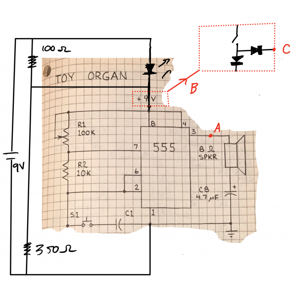
My oscillator circuit is here - it's basically the Toy Organ circuit from the same book, but I'm going to swap R1 and R2 for pots so it can be tuned, and put probably like 10 of these in parallel, activated by a keyboard (no poly sounds here, just single keys). And I put an LED with a voltage divider as well.

This guy works, but I do have a question: If the frequency comes from the cycling of R1C and R2C, why does changing the capacitor between the speaker and ground (say, 4.7 uF to 1.5 uF) change the frequency? (I've checked, it changes it dramatically)
Regardless of that answer, I can probably adapt to small changes to my calculated frequencies by just giving myself enough room with the pots. But, I also want to add an AREG (and probably a VCA). I grabbed the one from the Noise Toaster and removed the repeating circuit (second image). First, I tried to put it "in front" of the 555, either putting the output (D) on the high end, or across pin 8/4 of the 555. Although the envelope filter worked, it had a substantial effect on the frequency, and since I don't want to have to retune the synth after changing the envelope settings, that's unworkable.
So, I thought I would put the AERG on the output of the 555 - that's the additional notation in the circuit. So I use a switch to engage both (box B), and used a transistor as a VCA to get to the speaker (that was like a chatGPT frankencircuit, I can't say I totally understand that...). But now, the envelope is *not* working and the sound amplitude is much reduced.

Anyone have any thoughts on the best way to combine these two / three circuits? I want to use an AERG to modify the notes from my synth, but I want the tuning of those notes to be unaffected by settings in the AERG. I'd rather use AERG as built (since I know I can build it!), but I'll take "build it differently" too....
Thanks!
| Description: |
|
| Filesize: |
2.42 MB |
| Viewed: |
18 Time(s) |
| This image has been reduced to fit the page. Click on it to enlarge. |
|
| Description: |
|
| Filesize: |
1.18 MB |
| Viewed: |
16 Time(s) |
| This image has been reduced to fit the page. Click on it to enlarge. |

|
|
|
|
Back to top
|
|
 |
PHOBoS
Joined: Jan 14, 2010
Posts: 5792
Location: Moon Base
Audio files: 709
|
Posted: Mon Dec 23, 2024 4:13 pm Post subject:
Re: 555 Synth questions and AREG Help
Subject description: My first build, I want to check some stuff |
|
|
 
| Quote: | | My oscillator circuit is here - it's basically the Toy Organ circuit from the same book, but I'm going to swap R1 and R2 for pots so it can be tuned, and put probably like 10 of these in parallel, activated by a keyboard (no poly sounds here, just single keys). And I put an LED with a voltage divider as well. |
I am confused by your voltage divider or rather its supposed function. For the LED you'd just need to limit the current with a single resistor
and if you want the to limit the voltage for the 555 for some reason you'd need something more stable like a voltage regulator.
For an organ like arrangement you can use a single 555, it's not exactly clear to me if that is what you have in mind. I'd keep a fixed resistor
for R2 and a series of pots (in the position of R1) + switches for the different notes. I would recommend putting as fixed resistor in series with the
pots as well so the value can never be 0. You can use a single resistor for this that all the pots connect to. I'd put it on the side that is connected to
pin 7 and then the other side of the pots can be connected with switches to the positive supply and the same switches can than be used to trigger
an envelope generator. I think this is kinda what you're hinting at with [ B ].
Slight problem or maybe bonus feature with this setup is that you can press multiple keys at once which would give a whole range of extra frequencies.
You could also experiment with using pin 5 of the 555 which is the CV input. It can change the threshold voltage which will also change the frequency.
| Quote: | | This guy works, but I do have a question: If the frequency comes from the cycling of R1C and R2C, why does changing the capacitor between the speaker and ground (say, 4.7 uF to 1.5 uF) change the frequency? (I've checked, it changes it dramatically) |
Does it also do that when you don't use a voltage divider and connect the 555 straight to 9V ?
It will probably alter the color of the sound a bit since it works as a high-pass filter but the frequency shouldn't change a lot.
My guess is that with the voltage divider you'd get a higher frequency with a larger capacitor value since it would draw a larger current
resulting in a voltage drop caused by the voltage divider which in turn results in a faster oscillation. I could be wrong though.
| Quote: | | Regardless of that answer, I can probably adapt to small changes to my calculated frequencies by just giving myself enough room with the pots. But, I also want to add an AREG (and probably a VCA). I grabbed the one from the Noise Toaster and removed the repeating circuit (second image). First, I tried to put it "in front" of the 555, either putting the output (D) on the high end, or across pin 8/4 of the 555. Although the envelope filter worked, it had a substantial effect on the frequency, and since I don't want to have to retune the synth after changing the envelope settings, that's unworkable. |
Envelope generator should come after the sound generation, assuming you want to change the amplitude and not the frequency.
The VCA part can be a bit tricky to make if you want to keep it simple but since a 555 produces square waves it's actually not that hard.
Driving a speaker directly with it can complicate things though and it'll be a lot easier to drive it with a separate amplifier.
An LM386 comes to mind for that but these days there are probably more efficient solutions, especially if you plan on running it from a battery.
I would focus on getting the organ part working first and than look into an envelope generator since it's pretty much a separate circuit.
In the meantime you might find some useful information in my build thread of the Lun-A-Key. It doesn't use a 555 for sound generation
but does have a fairly simple envelope generator. https://electro-music.com/forum/topic-57015.html
_________________
"My perf, it's full of holes!"
http://phobos.000space.com/
SoundCloud BandCamp MixCloud Stickney Synthyards Captain Collider Twitch YouTube |
|
|
Back to top
|
|
|
PHOBoS
Joined: Jan 14, 2010
Posts: 5792
Location: Moon Base
Audio files: 709
|
|
|
Back to top
|
|
|
thethinker
Joined: Dec 22, 2024
Posts: 2
Location: USA
|
Posted: Tue Dec 24, 2024 5:05 pm Post subject:
Re: 555 Synth questions and AREG Help
Subject description: My first build, I want to check some stuff |
|
|
This is an incredibly helpful response to me at the moment I'm at right now, thank you so much for it.
| PHOBoS wrote: |
| Quote: | | My oscillator circuit is here - it's basically the Toy Organ circuit from the same book, but I'm going to swap R1 and R2 for pots so it can be tuned, and put probably like 10 of these in parallel, activated by a keyboard (no poly sounds here, just single keys). And I put an LED with a voltage divider as well. |
I am confused by your voltage divider or rather its supposed function. For the LED you'd just need to limit the current with a single resistor
and if you want the to limit the voltage for the 555 for some reason you'd need something more stable like a voltage regulator. |
Yes, explain to me why it's wrong! To me, an LED is just something that requires a minimum potential (although I know it has current limits), so I just calculated what the voltage would be needed, gave that to the LED, and the rest to the 555. If that's causing problems, I got no issue getting rid of it, but I'd like a cute little LED to tell me if the battery is dead when I turn the thing on. Should I do like, LED in series with a resistor across the whole 9V, rather then a divider?
| Quote: | For an organ like arrangement you can use a single 555, it's not exactly clear to me if that is what you have in mind. I'd keep a fixed resistor
for R2 and a series of pots (in the position of R1) + switches for the different notes. I would recommend putting as fixed resistor in series with the
pots as well so the value can never be 0. You can use a single resistor for this that all the pots connect to. I'd put it on the side that is connected to
pin 7 and then the other side of the pots can be connected with switches to the positive supply and the same switches can than be used to trigger
an envelope generator. I think this is kinda what you're hinting at with [ B ]. |
Well actually I was thinking about replacing the capacitor between 2 and 1 with a capacitor + pot + switch in series, because changing the capacitor seemed to be able to give me better control of the frequency generation - I'm going for an organ that covers about an octave, and just playing with the numbers it seemed to work a little better (and modifying the frequency calculation should be easy, since that series resistor will get hit on both the charge and discharge). But I also did just prototype a version of yours (corresponding to your picture in your other post, basically), and it was easy to estimate the capacitor / resistor combinations to hit 440 Hz. I'll consider which version makes the most sense.
| Quote: | | Slight problem or maybe bonus feature with this setup is that you can press multiple keys at once which would give a whole range of extra frequencies. |
Oh rad, I'd love for that to be part of this! Could actually be quite musical, particularly with a working attack envelope.
| Quote: | | You could also experiment with using pin 5 of the 555 which is the CV input. It can change the threshold voltage which will also change the frequency. |
Yeah I think I get that. I guess I could make that and "octave range selector", but I'd have to redo the calculations for fequencies...I'll probably leave it alone, I'm clearly pushing my knowledge of this system already!
| Quote: | | Quote: | | This guy works, but I do have a question: If the frequency comes from the cycling of R1C and R2C, why does changing the capacitor between the speaker and ground (say, 4.7 uF to 1.5 uF) change the frequency? (I've checked, it changes it dramatically) |
Does it also do that when you don't use a voltage divider and connect the 555 straight to 9V ?
It will probably alter the color of the sound a bit since it works as a high-pass filter but the frequency shouldn't change a lot.
My guess is that with the voltage divider you'd get a higher frequency with a larger capacitor value since it would draw a larger current
resulting in a voltage drop caused by the voltage divider which in turn results in a faster oscillation. I could be wrong though. |
Ah ok I guess that makes sense. So, I've removed the LED to study the vanilla system a little more carefully. Now with a variety of capacitors, I get a variety of frequencies (with specific pots/Rs/C)...
4.7 uF -> 440 Hz
47 uF -> 432 Hz
10 uF -> 435 Hz
But, as I messed around, these were not *exactly* reproduceable....switching them forwards and backwards just kinda hovered around 440 Hz, with smaller values kinda being higher frequencies. Perhaps I should not worry about this, and just build to 4.7 uF.
| Quote: | | Quote: | | Regardless of that answer, I can probably adapt to small changes to my calculated frequencies by just giving myself enough room with the pots. But, I also want to add an AREG (and probably a VCA). I grabbed the one from the Noise Toaster and removed the repeating circuit (second image). First, I tried to put it "in front" of the 555, either putting the output (D) on the high end, or across pin 8/4 of the 555. Although the envelope filter worked, it had a substantial effect on the frequency, and since I don't want to have to retune the synth after changing the envelope settings, that's unworkable. |
Envelope generator should come after the sound generation, assuming you want to change the amplitude and not the frequency.
The VCA part can be a bit tricky to make if you want to keep it simple but since a 555 produces square waves it's actually not that hard.
Driving a speaker directly with it can complicate things though and it'll be a lot easier to drive it with a separate amplifier.
An LM386 comes to mind for that but these days there are probably more efficient solutions, especially if you plan on running it from a battery. |
Yeah on this: I'm planning on external amplification, like a standard guitar amp. I am also kinda on the downlow hoping to have a flip that engages a piezo strapped to some kind of vibratable object - like a viola bridge with a mic? Or even a chamber of some kind? Just to give another option for sound. But who knows, I might even need that LM386 circuit to drive the piezo, I haven't prototyped any of that.
| Quote: | I would focus on getting the organ part working first and than look into an envelope generator since it's pretty much a separate circuit.
In the meantime you might find some useful information in my build thread of the Lun-A-Key. It doesn't use a 555 for sound generation
but does have a fairly simple envelope generator. https://electro-music.com/forum/topic-57015.html |
I hear you, and that's my plan now. I've got your prototype working now, maybe I'll try mine with a few different C/pot combinations, see what seems reasonable, and then move onto the AREG. (I see that part of your Lun-A-Key uses a 555 also, right? That might be cool, as kind of a theme build....). I guess I'd rather try for the noise toaster, since I've already invested some time into understanding it. I'll work on this and get back to you.
Again, VERY helpful, thanks! |
|
|
Back to top
|
|
|
PHOBoS
Joined: Jan 14, 2010
Posts: 5792
Location: Moon Base
Audio files: 709
|
Posted: Sun Dec 29, 2024 4:59 am Post subject:
Re: 555 Synth questions and AREG Help
Subject description: My first build, I want to check some stuff |
|
|
| thethinker wrote: | | Should I do like, LED in series with a resistor across the whole 9V, rather then a divider? |
yes. you only need to limit the maximum current, the voltage across the LED is already limited by the LED itself.
What this voltage is depends on the used LED and also varies a bit with the amount of current.
It's roughly 2V for Red LEDs and 3V for Yellow/Green LEDs, or at least it was. With current technologies they all seem
to be closer to 2V and unless you have a datasheet for the specific LED you use you're better off to just test what works.
For a standard LED the max current is usually 20mA but with how bright they are you might not need more than 10% of that (2mA).
Especially blue and white LED only need a very low current to be visible without being blinding, at least in my experience.
Calculating the correct resistor value is not very different from what you already did with the voltage divider except that
one resistor is replaced by an LED and it already has a fixed voltage across it. You could start with assuming the voltage drop
across the LED is 2V and need a current of 10mA, that'll give you enough info to calculate what value the resistor should be.
Once you've done that you can test how it looks and adjust the resistor value to your liking.
In practice you'll rarely have to do any calculations for this unless you want the absolute max brightness
or are working with a very different voltage than you are used to. Most of the time it comes down to
experimentation.
_________________
"My perf, it's full of holes!"
http://phobos.000space.com/
SoundCloud BandCamp MixCloud Stickney Synthyards Captain Collider Twitch YouTube |
|
|
Back to top
|
|
|
blue hell
Site Admin

Joined: Apr 03, 2004
Posts: 24391
Location: The Netherlands, Enschede
Audio files: 296
G2 patch files: 320
|
| Posted: Sun Dec 29, 2024 6:39 am Post subject:
|
|
|
And if you need to know .. your multimeter's diode tester may be able to reach 2 to 3 Volt .. may 
_________________
Jan
also .. could someone please turn down the thermostat a bit.
 |
|
|
Back to top
|
|
|
|

 Forum index » DIY Hardware and Software
