| Author |
Message |
PHOBoS

Joined: Jan 14, 2010
Posts: 5947
Location: Moon Base
Audio files: 709
|
 Posted: Sat Feb 23, 2013 5:01 pm Post subject:
Lunetta keyboard controller Posted: Sat Feb 23, 2013 5:01 pm Post subject:
Lunetta keyboard controller
Subject description: modifying a toy keyboard for lunetta use |
  |
|
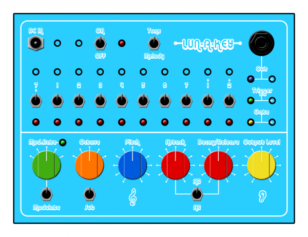
This is a project I'm currently working on and instead of waiting untill it's completely finished I'll post the progress I make
along the way.
It started when I went back to think about what i was gonna do with the Schrödinger II circuit. One thing that came to mind was to make
a stylophone controller for it, which then lead to the idea of using a small keyboard instead, using a cheap (€1,-) toy keyboard.
Initially I wanted to add a trimpot for each key or maybe a resistor string, but it turned out that the PCB was so small it would be hard to
solder anything to. So I ditched that idea and played around using the output of the keyboard to control another oscillator, and this gave me
the idea to just square up the output and use it as a tuned oscillator.
first a little more info about the keyboard I'm using. It has 10 keys, tuned to major intervals (white keys). When you press a key a tone will
only play for a certain duration so it stops even when the key is still pressed down. It also has a switch that puts it into melody mode.
In this mode each key plays a different melody, restarting from the first note everytime you press a key. It runs on 2AA batteries and has
a small speaker.
So now to square up the output. Well this turned out to be a lot easier then I could have hoped for because when I connected my scope to the
output a nice squarewave allready appeared  Since the keyboard runs on 3V, the output voltage isn't high enough to control anything Since the keyboard runs on 3V, the output voltage isn't high enough to control anything
directly. However, as it turns out, it's an open collector output (there is no extra transistor on the PCB though), with the speaker connected
between +3V and the output. So all that's needed was a pullup resistor, connected to the voltage I want to use, instead of the speaker.
Followed by an inverting buffer for which i used a 40106. For the sound itself it doesn't have to be inverted but when there is no sound
I like the output to be low.
of course I couldn't just leave it at that. So I'm also adding remote inputs for every key (Lunetta controlled keyboard for nice sequences),
a Gate output which is high as long as a key is pressed, and a Trigger output which gives a short pulse everytime a key is pressed even
when another key is still held down. And some indicator LED's for every key.
of course I couldn't just leave it at that. So I'm also adding a simple AD/AR generator to control a very simple transistor VCA, a 4040
divider and a switch to select different octaves, which is also used to add suboctave and modulation to the sound. And a potentiometer to
control the pitch, which also affects the note length.
And I hope I can leave it at that. 
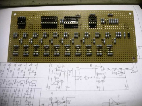
To be able to do all this I did have to solder wires to the PCB afterall, so I used some thin enameled wires and soldered them to a piece of perf
with a printconnector on it. This will make it easy to solder wires to it later. I also added a 3V supply using an LM317L.
I'm currently soldering the main PCB, So more info later.
But here are some photo's.
| Description: |
|
| Filesize: |
50.24 KB |
| Viewed: |
870 Time(s) |
| This image has been reduced to fit the page. Click on it to enlarge. |

|
| Description: |
| soldering small wires, lighter for reference |
|
| Filesize: |
40 KB |
| Viewed: |
866 Time(s) |
| This image has been reduced to fit the page. Click on it to enlarge. |

|
| Description: |
| connector, 3V supply and pitch pot. installed |
|
| Filesize: |
54.8 KB |
| Viewed: |
892 Time(s) |
| This image has been reduced to fit the page. Click on it to enlarge. |

|
_________________
"My perf, it's full of holes!"
http://phobos.000space.com/
SoundCloud BandCamp MixCloud Stickney Synthyards Captain Collider Twitch YouTube
Last edited by PHOBoS on Sun Jan 05, 2014 4:13 am; edited 4 times in total |
|
|
Back to top
|
|
 |
PHOBoS
Joined: Jan 14, 2010
Posts: 5947
Location: Moon Base
Audio files: 709
|
| Posted: Sat Feb 23, 2013 6:00 pm Post subject:
|
|
|
soldering,...
| Description: |
| main PCB, under construction |
|
| Filesize: |
49.73 KB |
| Viewed: |
902 Time(s) |
| This image has been reduced to fit the page. Click on it to enlarge. |

|
| Description: |
| some more components added |
|
| Filesize: |
48.29 KB |
| Viewed: |
910 Time(s) |
| This image has been reduced to fit the page. Click on it to enlarge. |
|
| Description: |
| just a couple of transistors and a big capacitor left, but that'll have to wait untill tomorrow. |
|
| Filesize: |
48.6 KB |
| Viewed: |
905 Time(s) |
| This image has been reduced to fit the page. Click on it to enlarge. |

|
_________________
"My perf, it's full of holes!"
http://phobos.000space.com/
SoundCloud BandCamp MixCloud Stickney Synthyards Captain Collider Twitch YouTube |
|
|
Back to top
|
|
|
PHOBoS
Joined: Jan 14, 2010
Posts: 5947
Location: Moon Base
Audio files: 709
|
|
|
Back to top
|
|
|
PHOBoS
Joined: Jan 14, 2010
Posts: 5947
Location: Moon Base
Audio files: 709
|
|
|
Back to top
|
|
|
Cynosure
Site Admin

Joined: Dec 11, 2010
Posts: 1029
Location: Toronto, Ontario - Canada
Audio files: 82
|
| Posted: Sun Feb 24, 2013 12:14 pm Post subject:
|
|
|
Very cool project. I can't wait for a demo 
_________________
JacobWatters.com |
|
|
Back to top
|
|
|
PHOBoS
Joined: Jan 14, 2010
Posts: 5947
Location: Moon Base
Audio files: 709
|
|
|
Back to top
|
|
|
PHOBoS
Joined: Jan 14, 2010
Posts: 5947
Location: Moon Base
Audio files: 709
|
| Posted: Sun Feb 24, 2013 3:57 pm Post subject:
|
|
|
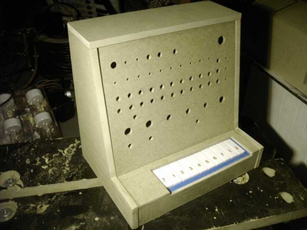
not the best picture but It'll give you an idea. the piece on top is just some scrap wood (might be usefull to cover the keyboard).
and an updated cover design
| Description: |
|
| Filesize: |
25.44 KB |
| Viewed: |
974 Time(s) |
| This image has been reduced to fit the page. Click on it to enlarge. |

|
| Description: |
|
| Filesize: |
82.54 KB |
| Viewed: |
858 Time(s) |
| This image has been reduced to fit the page. Click on it to enlarge. |

|
_________________
"My perf, it's full of holes!"
http://phobos.000space.com/
SoundCloud BandCamp MixCloud Stickney Synthyards Captain Collider Twitch YouTube |
|
|
Back to top
|
|
|
analog_backlash

Joined: Sep 04, 2012
Posts: 393
Location: Aldershot, UK
Audio files: 21
|
| Posted: Sun Feb 24, 2013 6:05 pm Post subject:
|
|
|
Fascinating as always, PHOBoS. I'm glad that the Schrödinger II had a very minor role (a very, very, very minor role ) in the chain of events leading to this device. I'll be interested to hear the results.
I'm actually building stuff at the moment (not just faffing around on breadboards as usual), so I should have something to show for it (eventually). I'm working on a proper (but miniature) lunetta at the moment. I might have a look back at some of your circuits for the Modular Lunetta and Bandersnatch for inspiration (don't worry, you'll get credited for anything that inspires me). I also want to start doing some proper recordings soon, rather than my usual random noise recordings.
I shall look out for further installments...
Gary |
|
|
Back to top
|
|
|
PHOBoS
Joined: Jan 14, 2010
Posts: 5947
Location: Moon Base
Audio files: 709
|
Posted: Sun Feb 24, 2013 8:17 pm Post subject:
Lun-A-Key
Subject description: Gate and Trigger circuit |
|
|
The cat's not dead yet (I'm thinking of making a full schrödinger synth out of it  ). ).
I look forward to see what you're working on and it would be great if you could make use of some of the things I've posted 
--------------------------------------------------------------
ok here's the first schematic (I'll post it in bits, since it's quite large and easier to understand in parts) . The Gate and Trigger circuits aswell
as the external control inputs for the keyboard. I've only drawn it for 2 keys, but in reality there are 10.
starting of with those, the keys of the keyboard are just switches that connect a 'KEY' point to the positive supply of the keyboard (3V),
so it's pretty easy to control these with an external signal. I want to use an input voltage in the range of 5-12V which would probably fry
the circuit in an instant. So I added a voltage divider (33K + 68K resistors) which has an output voltage of 3.3V with an input of 5V.
With the voltagedrop over the diode that's in series, there will be ±2.7V left, which is a safe value and enough to trigger the keyboard.
And if the input voltage is higher then 5V, the zenerdiode will still keep it at that.
next the Gate circuit which is very simple. An OR-gate made with diodes and a resistor, followed by a transistor, because the voltage is too
low to trigger a CMOS gate directly, which is in turn buffered by a schmitt trigger inverter (40106). Because the transistor allsoy inverts,
there is no need to add an extra inverter.
The trigger circuit also includes the LED indicators. The transistor, in combination with the 1nF capacitor and pull up resistors (one in series
with the LED), creates a very short high to low pulse.The pulses of all the keys are then combined, again using the same diode resistor configuration
of the OR gate but inverted, so with a pullup resistor and the diodes reversed (it's an AND  ). If you're looking for the pull-up resistor it's the ). If you're looking for the pull-up resistor it's the
1M attached to pin 5 of the 555 timer. The 555 is used in monostable mode and turns it a into a neat trigger signal. The 10nF caps attached to
the base of the transistors are to debounce the keys of the keyboard.
more next time 
NOTE: the current through the zenerdiodes is too small for them to work, so in the final design I placed 4K7 resistors in parallel
with the 33K resistors.
| Description: |
|
| Filesize: |
52.01 KB |
| Viewed: |
948 Time(s) |
| This image has been reduced to fit the page. Click on it to enlarge. |

|
_________________
"My perf, it's full of holes!"
http://phobos.000space.com/
SoundCloud BandCamp MixCloud Stickney Synthyards Captain Collider Twitch YouTube
Last edited by PHOBoS on Thu Feb 28, 2013 9:15 am; edited 1 time in total |
|
|
Back to top
|
|
|
PHOBoS
Joined: Jan 14, 2010
Posts: 5947
Location: Moon Base
Audio files: 709
|
|
|
Back to top
|
|
|
PHOBoS
Joined: Jan 14, 2010
Posts: 5947
Location: Moon Base
Audio files: 709
|
|
|
Back to top
|
|
|
PHOBoS
Joined: Jan 14, 2010
Posts: 5947
Location: Moon Base
Audio files: 709
|
|
|
Back to top
|
|
|
wmonk
Joined: Sep 15, 2008
Posts: 529
Location: Enschede, the Netherlands
Audio files: 15
|
| Posted: Mon Feb 25, 2013 5:55 pm Post subject:
|
|
|
| PHOBoS wrote: |
Recently I cut my keyboard in half. |

Great looking project Phobos! And that thing is /small/. Where did you find those keys?
_________________
Weblog! |
|
|
Back to top
|
|
|
PHOBoS
Joined: Jan 14, 2010
Posts: 5947
Location: Moon Base
Audio files: 709
|
| Posted: Mon Feb 25, 2013 6:45 pm Post subject:
|
|
|
Thanks
I got that keyboard (incl. keys) at one of those €1,- shops a couple years ago. I have some slightly different, animal shaped ones too .
If you need small keys visit a toystore, they usually have some small cheap keyboards or if you're lucky you'll find something at a
'kringloopwinkel' (no need to translate that for you )
_________________
"My perf, it's full of holes!"
http://phobos.000space.com/
SoundCloud BandCamp MixCloud Stickney Synthyards Captain Collider Twitch YouTube
Last edited by PHOBoS on Mon Feb 25, 2013 7:53 pm; edited 1 time in total |
|
|
Back to top
|
|
|
kkissinger
Stream Operator

Joined: Mar 28, 2006
Posts: 1472
Location: Kansas City, Mo USA
Audio files: 45
|
| Posted: Mon Feb 25, 2013 6:52 pm Post subject:
|
|
|
Very nice project, Phobos. Look forward to hearing it!
_________________
-- Kevin
http://kevinkissinger.com |
|
|
Back to top
|
|
|
PHOBoS
Joined: Jan 14, 2010
Posts: 5947
Location: Moon Base
Audio files: 709
|
|
|
Back to top
|
|
|
Draal

Joined: May 18, 2010
Posts: 308
Location: Oak Park, IL
Audio files: 5
|
| Posted: Tue Feb 26, 2013 5:31 am Post subject:
|
|
|
Things are really shaping up! Been busy working on my tube guitar amp and a mini synth to follow this until recently.
I wish I had these wood skills myself.
_________________
Zontar Prevails! |
|
|
Back to top
|
|
|
PHOBoS
Joined: Jan 14, 2010
Posts: 5947
Location: Moon Base
Audio files: 709
|
| Posted: Tue Feb 26, 2013 7:51 am Post subject:
|
|
|
oh, but your woodworking skills are amazing Draal
just different.
It's all done with a (electric) jigsaw, a file, some sanding paper, sweat and a bit of patience. And I don't use real wood, which makes it a lot easier
to work with. Everything is just glued together by the way, no screws or nails.
----------------
Switches, pots and knob did arrive today as planned so I can continue with that. I did have another idea yesterday which is using the inputs
that control the keyboard also as outputs to control something else, so you can use the keyboard as a row of 10 pushbuttons. I allready have
toggle switches to turn the inputs off so I could do it,. but it would need some extra buffers though.
_________________
"My perf, it's full of holes!"
http://phobos.000space.com/
SoundCloud BandCamp MixCloud Stickney Synthyards Captain Collider Twitch YouTube |
|
|
Back to top
|
|
|
PHOBoS
Joined: Jan 14, 2010
Posts: 5947
Location: Moon Base
Audio files: 709
|
|
|
Back to top
|
|
|
Draal
Joined: May 18, 2010
Posts: 308
Location: Oak Park, IL
Audio files: 5
|
| Posted: Wed Feb 27, 2013 8:16 am Post subject:
|
|
|
 
The progress on this has been fun to watch. I know I have a kiddie keyboard somewhere in this house of toys  . .
_________________
Zontar Prevails! |
|
|
Back to top
|
|
|
analog_backlash
Joined: Sep 04, 2012
Posts: 393
Location: Aldershot, UK
Audio files: 21
|
| Posted: Wed Feb 27, 2013 1:08 pm Post subject:
|
|
|
Really boring question PHOBoS. It looks like you're using MDF for your housing(s). How thick is the piece that you're mounting the controls on? I only say this as I tend to use a lot of 3.5mm jack sockets and I usually have to mount them on aluminium, steel or plastic sheeting, as the thread lengths are so short. I think that MDF will be too thick (or so thin that you could put your finger through it  ). ).
It looks like it's coming along nicely, by the way.
Gary |
|
|
Back to top
|
|
|
PHOBoS
Joined: Jan 14, 2010
Posts: 5947
Location: Moon Base
Audio files: 709
|
| Posted: Wed Feb 27, 2013 1:39 pm Post subject:
|
|
|
Yes it's MDF, the front is 4mm which is indeed too thick for sockets, but I've still managed to use them by using a chisel and carving some
layers away, If you have a completely round 3.5mm jack socket it's easier because you can use a large drillbit, I've done this for those
DC input jacks. But be careful if you do it this way,. don't put it in a drill just turn it carefully by hand. You might be able to use a drillpress
but you would have to be VERY careful, else you just end up with a large hole.
here's an example from my PWM lunetta,.. look at the sockets at the top:

the sides and top are 8mm btw and I used a heavier 12mm piece for the bottom to add some more stability. (I used 18mm for the Bandersnatch).
-------------
I now have everything wired up,. so next is going to be the hold-your-breath-and-turn-it-on-and-hope-there-isn't-any-smoke part.
The painting set me back a bit timewise, I'm doing a duotone but one color kept messing up the other. I think it's ok now just needs some
clear coating. If I can resist I'll let it harden further until tomorrow before I put it together, allthough it will be dry enough to handle.
_________________
"My perf, it's full of holes!"
http://phobos.000space.com/
SoundCloud BandCamp MixCloud Stickney Synthyards Captain Collider Twitch YouTube |
|
|
Back to top
|
|
|
PHOBoS
Joined: Jan 14, 2010
Posts: 5947
Location: Moon Base
Audio files: 709
|
|
|
Back to top
|
|
|
analog_backlash
Joined: Sep 04, 2012
Posts: 393
Location: Aldershot, UK
Audio files: 21
|
| Posted: Wed Feb 27, 2013 6:10 pm Post subject:
|
|
|
Thanks for the MDF advice. I've looked at the Wickes website and they do 3mm board, but that's probably still too thick and a bit flimsy. I think that your solution is the best compromise. MDF is cheaper than metal/plastic sheet and easier to cut, so I'll give it a go...
| PHOBoS wrote: | I wired the LED's the wrong way around  (I usually have them connected to GND). But no smoke, I've got power on all the IC sockets and I get 2.7 V when I press a keyboard key. So that's right sofar. (I usually have them connected to GND). But no smoke, I've got power on all the IC sockets and I get 2.7 V when I press a keyboard key. So that's right sofar.
so a little bit of rewiring and then I'll try again,.. |
Ah, so I'm not the only one who screws up then I've been working on my mini lunetta today and I spent about half an hour trying to work out why my LEDs weren't lighting up. I finally realised that they weren't connected to 0V I think it's because I'm using prototyping boards with individual copper pads for the first time and I'm still getting used to it. I'll probably post something soon about it, as it is now getting to the making noises stage
Gary |
|
|
Back to top
|
|
|
PHOBoS
Joined: Jan 14, 2010
Posts: 5947
Location: Moon Base
Audio files: 709
|
| Posted: Thu Feb 28, 2013 8:55 am Post subject:
|
|
|
| Quote: | | Ah, so I'm not the only one who screws up then |
everybody makes mistakes (except maybe fonik),. and I think it's pretty common for circuits not to work on the first go, allthough
it does happen.
-------------------------
After I rewired the LED's yesterday there was still one LED that didn't light up. I wondered if I put it in reversed again so desoldered it,
and tested it (couldn't really see what was anode or cathode) and it turned out to be dead. I used some different LED's then usual (waterclear)
of which I had just enough,. I almost went into panic mode, but luckely I did manage to find just one more. After replacing it all the LED's
lit up as they should.
So I inserted the 40106 and the 'Gate' and 'Out' LED's worked too. After that I put the 555 for the 'Trigger' output in place and that also
worked as it should.
Next the 4040 (octave switch, sub-octave and modulation). I could see if it worked by looking at the mod.rate LED, which seemed to work
except at one position of the rotary switch. So I checked what it was connected to and it turned out to be the wrong pin of the 4040.
It would actually blink really slow, but because the keyboard only produces short tones it didn't get a chance to turn off.
After I resoldered it to the correct pin I still wasn't really happy with the modulation rate. Originally I planned for a 4 step switch,.
but when I designed the front I changed it to 5 steps (I could have used 12, but the slow modulation is useless). So initially I choose
a larger division of the original squarewave for this 5th step, but in my opinion it was too slow,. so I shifted everything 1 step and
used a smaller division instead.
Finally there was one more chip to insert, the 555 for the AD/AR generator and with this inserted I could actually listen to it. Well,
I got sound but the AD/AR generator didn't seem to work as it should, it did something though. So I compared the schematic with the
PCB layout and noticed I had the timing capacitor in backwards, which of course I also put in the wrong way on the PCB itself. (this probably
happened after making some last minute changes for which I had to move some components around). After I replaced the cap (just to
be sure) the AD/AR generator worked too. allthough it doesn't always seem to retrigger but that's probably just how I designed it.
I might look into it, but it works well enough.
At this point I thought I had all systems running,. untill I tried the remote inputs. The key LED lit up, Trigger LED blinked, Gate LED lit up,
but no sound

So I measured the voltage going to the 'keypoint' on the keyboard and it was only ±1.2V. which should be 2.7V, hmm. I first removed the
connection between the input resistors and diodes and the rest of the circuit to see what voltage I got, but still the same. So I
removed the zenerdiode (keyboard disconnected) and now I got a voltage of ±6.6V which was correct. Well, what i didn't keep in mind
was that a zenerdiode needs some current flowing through it to work, and I had done just the opposite, that is trying to keep the current
through the diode to a minimum. So I just needed to reduce the input resistor (33K) and to make life easy I didn't remove it from
the PCB but just soldered a 4K7 resistor in parallel. After this modification the remote inputs worked perfect. So at this point it was
finally all working as it should.
One final change I made was change the series resistors of the Gate/Trigger/Out LED's which were not bright enough in my opinion.
The Gate and Trigger LED's are both waterclear which usually are also pretty bright but not these ones. And the Out LED is a blue
one, which can be pretty bright, but because it's actually blinking with a 50% dutycyle it's not as bright as when it's just on.
I'll post some schematics later. I'm still working on the paint now. I put some clear coating on this morning, but I should have put
down some fresh newspapers because the force of the spray lifted the paintdust of which landed where it shouldn't  . .
So I had to repaint a bit again. But I should be able to put it together today.
Allready had a bit of fun with it last night making some simple sequences 
_________________
"My perf, it's full of holes!"
http://phobos.000space.com/
SoundCloud BandCamp MixCloud Stickney Synthyards Captain Collider Twitch YouTube |
|
|
Back to top
|
|
|
|

 Forum index » DIY Hardware and Software » Lunettas - circuits inspired by Stanley Lunetta