| Author |
Message |
yusynth

Joined: Nov 24, 2005
Posts: 1314
Location: France
|
 Posted: Sat Jan 01, 2011 6:11 am Post subject:
A NEW (IMPROVED) VERSION OF THE YUSYNTH ADSR Posted: Sat Jan 01, 2011 6:11 am Post subject:
A NEW (IMPROVED) VERSION OF THE YUSYNTH ADSR |
  |
|
Hi All
I now propose an improved design of the yusynth ADSR.
The changes are :
Now the input stage is a discrete Schmitt trigger. As such any signal (this means not necessarily a regular GATE signal) can be used to trigger the ADSR as soon as its level goes above 2V.
The input impedance is now very high which makes it possible to feed more than four ADSR on the same GATE signal source without problem.
A buffering stage as been added between the SUSTAIN potentiometer and the DECAY potentiometer. This fixes a slight bug that made the DECAY rate dependant of the SUSTAIN setting. Now they are completly independant.
A short/long envelope option is now provided by setting jumpers on the PCB which select proper timing capacitors and ATTACK resistors. Note that this can be as well connected to an "on panel" DPDT switch to allow interactive selection of the ADSR mode.
And ultimatly, a resistor can be added or ignored to set the range of the REVERSE ADSR mode. Without resistor, the range is 0V (quiet status) to -10V (max range); with the the resistor installed, the range is +10V (quiet mode) to 0V (max range).
Check this at http://yusynth.net/Modular/EN/ADSR/index.html
Another important change is that from now the yusynth PCBs will provide prints for both DOTCOM style PSU connector and MOTM style PSU connector !
_________________
Yves
Last edited by yusynth on Mon Jan 03, 2011 9:13 am; edited 1 time in total |
|
|
Back to top
|
|
 |
Sebo

Joined: Apr 27, 2007
Posts: 564
Location: Argentina
|
| Posted: Sat Jan 01, 2011 7:31 am Post subject:
|
|
|
That's great!!!
I will build one for my new cabinet.
Thanks for sharing it, and happy 2011!!!
_________________
Sebo
---------------------------------------
My Music:
https://www.facebook.com/cosaquitos/ |
|
|
Back to top
|
|
|
mph

Joined: Aug 25, 2007
Posts: 87
Location: France
|
| Posted: Sat Jan 01, 2011 9:20 am Post subject:
|
|
|
Thanks Yves!
So I plan to build two more ADSR, now with the updated version, when I'd have finished the main cabinet!
It's going to be a very busy year.
Happy new year. |
|
|
Back to top
|
|
|
iopop3
Joined: May 28, 2010
Posts: 94
Location: Malmö, Sweden
|
| Posted: Sat Jan 01, 2011 12:30 pm Post subject:
|
|
|
The bom say, "(or any other CMOS version of the NE555, DO NOT USE A NE555 !)".
Is this because a cmos version of the 555 is more stable, draws less current and overall improved compared to the original NE555. Or are there other reasons? |
|
|
Back to top
|
|
|
yusynth
Joined: Nov 24, 2005
Posts: 1314
Location: France
|
| Posted: Sat Jan 01, 2011 2:07 pm Post subject:
|
|
|
| iopop3 wrote: | The bom say, "(or any other CMOS version of the NE555, DO NOT USE A NE555 !)".
Is this because a cmos version of the 555 is more stable, draws less current and overall improved compared to the original NE555. Or are there other reasons? |
No other reasons, you summarized them all very well.
_________________
Yves |
|
|
Back to top
|
|
|
chrisp

Joined: Jan 14, 2010
Posts: 7
Location: Athens,Greece
|
| Posted: Sun Jan 02, 2011 8:21 pm Post subject:
|
|
|
nooooooo i just finessed 10 old!! ADSRs and now i wait the front panels 
Happy 2011  |
|
|
Back to top
|
|
|
yusynth
Joined: Nov 24, 2005
Posts: 1314
Location: France
|
| Posted: Mon Jan 03, 2011 12:19 am Post subject:
|
|
|
| chrisp wrote: | nooooooo i just finessed 10 old!! ADSRs and now i wait the front panels
Happy 2011 |
No worry, the old ADSRs are working well, the new one are just doing better 
_________________
Yves |
|
|
Back to top
|
|
|
kkissinger
Stream Operator

Joined: Mar 28, 2006
Posts: 1429
Location: Kansas City, Mo USA
Audio files: 45
|
| Posted: Mon Jan 03, 2011 9:07 am Post subject:
Re: A NEW (IMPROVED) VERSION OF THE YUSYNTH ADSR |
|
|
| yusynth wrote: | | The input impedance is not very high which makes it possible to feed more than four ADSR on the same GATE signal source without problem. |
Excellent, Yves.
You probably meant to write that the input impedance is now very high.
Ah, I recognize the discreet schmidt trigger -- I've built three of your Logic boards so your schmidt trigger with the 1m resistor (and the 1.2m pulldown resistor) is like an old friend. 
_________________
-- Kevin
http://kevinkissinger.com |
|
|
Back to top
|
|
|
yusynth
Joined: Nov 24, 2005
Posts: 1314
Location: France
|
| Posted: Mon Jan 03, 2011 9:14 am Post subject:
|
|
|
| Quote: | | You probably meant to write that the input impedance is now very high. |
Yes you're right , I fixed the typo...
_________________
Yves |
|
|
Back to top
|
|
|
Danno Gee Ray
Joined: Sep 25, 2005
Posts: 1351
Location: Telford, PA USA
|
| Posted: Mon Jan 03, 2011 6:51 pm Post subject:
|
|
|
Yves,
The schematic, parts list, and the component location diagram show C-4 to be 10nf. The color wiring diagram shows this to be 15nf. I assume 10nf is the correct value?
Thanks,
Dan |
|
|
Back to top
|
|
|
yusynth
Joined: Nov 24, 2005
Posts: 1314
Location: France
|
| Posted: Tue Jan 04, 2011 12:15 am Post subject:
|
|
|
Yes it's 10n although 15n would'nt be a problem, I'll fix this discrepancy.
_________________
Yves |
|
|
Back to top
|
|
|
Franky

Joined: Dec 09, 2007
Posts: 57
Location: Grenoble - France
|
| Posted: Thu Jan 06, 2011 6:17 am Post subject:
|
|
|
Hello Yves,
It's nice to see this problem solved! Is it critical to switch the Attack limitation resistor as well as the caps? (I bet you understand why I'm asking you this )
Nice work anyway, an interesting mod would be to add a potentiometer to blend the normal and inverted outputs, to make a third output with polarized amount (negative on CCW, positive on CW, null when centered).
_________________
Forty Seven Effects |
|
|
Back to top
|
|
|
yusynth
Joined: Nov 24, 2005
Posts: 1314
Location: France
|
| Posted: Thu Jan 06, 2011 6:26 am Post subject:
|
|
|
| Franky wrote: | Hello Yves,
It's nice to see this problem solved! Is it critical to switch the Attack limitation resistor as well as the caps? (I bet you understand why I'm asking you this ) |
For sure I understand why As a matter of fact the switching of resistor is there to avoid overshoot of the attack for the shortest attack (1µF cap). For the project you are thinking of it is not a problem... makes it even more ...brutal...'
_________________
Yves |
|
|
Back to top
|
|
|
bubzy

Joined: Oct 27, 2010
Posts: 594
Location: United Kingdom
Audio files: 64
|
| Posted: Sat Jan 22, 2011 12:41 am Post subject:
|
|
|
| hi, ive etched and built this circuit. however im getting some strange behaviour from Q1. theres a short between C and E, although E is Not Connected. im no electronics genius just a lowly board stuffer, but everything looks to be ok, ive tried different transistors and that doesnt seem to work. if anyone can shed some light on what ive done wrong, that would be great. |
|
|
Back to top
|
|
|
yusynth
Joined: Nov 24, 2005
Posts: 1314
Location: France
|
| Posted: Sat Jan 22, 2011 1:36 am Post subject:
|
|
|
Last edited by yusynth on Tue Jan 25, 2011 6:04 am; edited 1 time in total |
|
|
Back to top
|
|
|
yusynth
Joined: Nov 24, 2005
Posts: 1314
Location: France
|
| Posted: Tue Jan 25, 2011 6:03 am Post subject:
|
|
|
| bubzy wrote: | | hi, ive etched and built this circuit. however im getting some strange behaviour from Q1. theres a short between C and E, although E is Not Connected. im no electronics genius just a lowly board stuffer, but everything looks to be ok, ive tried different transistors and that doesnt seem to work. if anyone can shed some light on what ive done wrong, that would be great. |
Sorry about that bubzy, but it seems that the PCB drawing on my site was missing a track between the Emitters of Q1 and Q2.
To solve your problem just solder a resistor leg in between the emitters pads and all will work fine. I don't understand why this track disappeared because it was there on my proto PCB.
Anyway I fixed the PCB drawing at my site and it can be used now.
_________________
Yves |
|
|
Back to top
|
|
|
bubzy
Joined: Oct 27, 2010
Posts: 594
Location: United Kingdom
Audio files: 64
|
| Posted: Wed Jan 26, 2011 12:08 am Post subject:
|
|
|
| Fantastic! Works very well, thank you for your replies and an excellent circuit! |
|
|
Back to top
|
|
|
JRock
Joined: Mar 05, 2010
Posts: 87
Location: Bucks County, PA
Audio files: 1
|
| Posted: Thu Feb 10, 2011 5:00 am Post subject:
|
|
|
Hi. I etched a pcb and built this but I can't seem to get it to work 
I used a TLC555 which is a CMOS chip. The LED doesn't light and the VCA and the filter just stay open when I plug them in. Any ideas?
I'll check out Q1 and Q2 and make sure their emitters are connected.
Thanks! |
|
|
Back to top
|
|
|
yusynth
Joined: Nov 24, 2005
Posts: 1314
Location: France
|
| Posted: Thu Feb 10, 2011 7:07 am Post subject:
|
|
|
| JRock wrote: | Hi. I etched a pcb and built this but I can't seem to get it to work
I used a TLC555 which is a CMOS chip. The LED doesn't light and the VCA and the filter just stay open when I plug them in. Any ideas?
I'll check out Q1 and Q2 and make sure their emitters are connected.
Thanks! |
Hi If you downloaded the PCB drawing before january 26th then you have to fix the Q1 emitter,Q2 emitter missing track bug. If you used the latest drawing then we will have to figure out what is the problem with your ADSR.
_________________
Yves
Last edited by yusynth on Thu Feb 10, 2011 7:41 am; edited 1 time in total |
|
|
Back to top
|
|
|
JRock
Joined: Mar 05, 2010
Posts: 87
Location: Bucks County, PA
Audio files: 1
|
| Posted: Thu Feb 10, 2011 7:29 am Post subject:
|
|
|
Wow. Thanks for the quick response! And thanks for your generous and well documented distribution of knowledge on your website! Your modules are awesome and I'll definitely be building more
I downloaded it a few weeks ago... I'm not positive when exactly. I'm just about to check it and contrast and compare and see which one I have. I keep you posted.
Thanks! |
|
|
Back to top
|
|
|
JRock
Joined: Mar 05, 2010
Posts: 87
Location: Bucks County, PA
Audio files: 1
|
| Posted: Thu Feb 10, 2011 8:35 am Post subject:
|
|
|
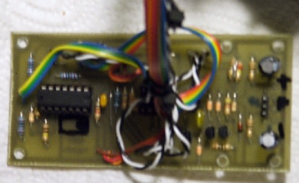
Awesome!!! It was the older version so I connected the emitters from Q1 and Q2 and it works
I have another question 
I added the DPDT switch to select fast or slow. When I use the gate button everything acts the way I would imagine but when I send a gate signal to the input the decay doesn't start until I've released the gate. Is that normal?
I connected the three fast/slow pads under the tantalum caps but not the 3 to the right of the diodes. Is that correct? |
|
|
Back to top
|
|
|
yusynth
Joined: Nov 24, 2005
Posts: 1314
Location: France
|
| Posted: Fri Feb 11, 2011 5:56 am Post subject:
|
|
|
| JRock wrote: | Awesome!!! It was the older version so I connected the emitters from Q1 and Q2 and it works
I have another question
I added the DPDT switch to select fast or slow. When I use the gate button everything acts the way I would imagine but when I send a gate signal to the input the decay doesn't start until I've released the gate. Is that normal?
I connected the three fast/slow pads under the tantalum caps but not the 3 to the right of the diodes. Is that correct? |
Can you send a photo of the assembled PCB ?
_________________
Yves |
|
|
Back to top
|
|
|
JRock
Joined: Mar 05, 2010
Posts: 87
Location: Bucks County, PA
Audio files: 1
|
|
|
Back to top
|
|
|
VW

Joined: Feb 06, 2011
Posts: 3
Location: Finland
|
|
|
Back to top
|
|
|
yusynth
Joined: Nov 24, 2005
Posts: 1314
Location: France
|
| Posted: Fri Feb 18, 2011 8:02 am Post subject:
|
|
|
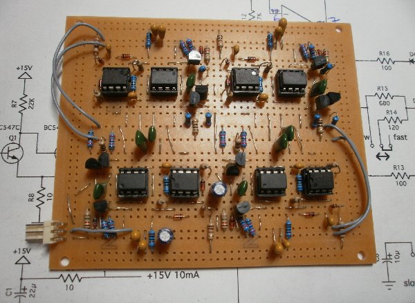
Nice quad ADSR !
_________________
Yves |
|
|
Back to top
|
|
|
|

 Forum index » DIY Hardware and Software » YuSynth