| Author |
Message |
DETOX
Joined: May 22, 2008
Posts: 143
Location: Germany
|
 Posted: Tue Dec 22, 2009 12:17 pm Post subject: Posted: Tue Dec 22, 2009 12:17 pm Post subject:
|
  |
|
i'm going to build a wsg on a stripboard tomorrow, i'll keep you updated !
_________________
Waldorf Pulse |
|
|
Back to top
|
|
 |
DETOX
Joined: May 22, 2008
Posts: 143
Location: Germany
|
| Posted: Tue Dec 22, 2009 5:27 pm Post subject:
|
|
|
| DETOX wrote: | | i'm going to build a wsg on a stripboard tomorrow, i'll keep you updated ! |
mpfff....didn't realize uncle krukus' version differs in some components but i need to buy some more resistors anyway so getting other capacitors won't be as anoying as it seems.
soldering for now was quite easy, transistors, jumper wires, ic sockets, a battery clip and two diodes are already installed (tje most annoying and time eating procedure was to attach the jumper wires, took me half an hour or smething...those stripboards are smaller than i expected).
but theres stilll one question i have (a question that tortures me for some time now not just since i thught about building a wsg...):
what's the matter with the ground? is it really just the negative pole of the 'power supply'?
_________________
Waldorf Pulse |
|
|
Back to top
|
|
|
Uncle Krunkus
Moderator

Joined: Jul 11, 2005
Posts: 4761
Location: Sydney, Australia
Audio files: 52
G2 patch files: 1
|
| Posted: Wed Dec 23, 2009 5:00 am Post subject:
|
|
|
| CLNicholson wrote: | | sorry to be such a bother but just one last question, i cant seem to find an exact double sized cap for those ratings. i need 40nF and 2uF but i did find 47nF and 2.2uF will those work just the same? thanks in advance! |
Sorry I didn't see this CLN.
Yeah they'd work fine.
_________________
What makes a space ours, is what we put there, and what we do there. |
|
|
Back to top
|
|
|
Uncle Krunkus
Moderator
Joined: Jul 11, 2005
Posts: 4761
Location: Sydney, Australia
Audio files: 52
G2 patch files: 1
|
| Posted: Wed Dec 23, 2009 5:06 am Post subject:
|
|
|
| DETOX wrote: | | what's the matter with the ground? is it really just the negative pole of the 'power supply'? |
I don't really know what you mean by this DETOX.
In a single supply, (ie no -ve supply) then yes, everything is referenced to the "negative pole of the power supply"
In a bi-polar supply, the ground is the point half way between the +ve and -ve supplies.
_________________
What makes a space ours, is what we put there, and what we do there. |
|
|
Back to top
|
|
|
benuron
Joined: Nov 22, 2009
Posts: 11
Location: Portugal
|
|
|
Back to top
|
|
|
Uncle Krunkus
Moderator
Joined: Jul 11, 2005
Posts: 4761
Location: Sydney, Australia
Audio files: 52
G2 patch files: 1
|
| Posted: Wed Dec 30, 2009 6:09 am Post subject:
|
|
|
Technically, you should put them on the copperside of the board, right underneath each chip. They are for bypassing the chip's supplies and therefore should be located as close as posssible to the chip's supply pins. Really though, in this circuit, it doesn't matter too much. That is the best practice though.
_________________
What makes a space ours, is what we put there, and what we do there. |
|
|
Back to top
|
|
|
benuron
Joined: Nov 22, 2009
Posts: 11
Location: Portugal
|
|
|
Back to top
|
|
|
azzthedrivein
Joined: Feb 07, 2010
Posts: 1
Location: byron bay Australia
|
| Posted: Mon Feb 08, 2010 4:32 pm Post subject:
Whacky Help????? |
|
|
Hi everyone, im totally new to forums and to this place especially. I am building the whacky noise thing from the diagrams shown below. i was wondering if it actually works from that diagram and also where and how do i attach the Audio Jack out. Any help would be greatly appreciated. Thanx
Aaron |
|
|
Back to top
|
|
|
stokes
Joined: Apr 29, 2006
Posts: 8
Location: Bristol, UK
|
| Posted: Wed Feb 10, 2010 4:58 pm Post subject:
|
|
|
| benuron wrote: | Thanks for sharing the wsg in stripboard layout 
I'm building it...but notice that the bypass caps (c9, c10) are missing.
Can I just solder this caps right next to + and - supply like in the picture?
Sorry I'm no electronics expert 
Thanks  |
Hi all,
I thought I'd test my rusty skills on this WSG before attempting something more serious, but am confused already.
What is the difference between the layout in Benuron's post (a few prior to this one) and the original Uncle Krunkus post on page 1 of the thread?
They seem to share the same components but I don't know if there are any functional differences between the two. I thought I was following the Uncle Krunkus layout but have accidentally cut my stripboard according to the length of Benuron's, which I have just noticed is a few holes shorter... 
Thanks
Stokes. |
|
|
Back to top
|
|
|
Uncle Krunkus
Moderator
Joined: Jul 11, 2005
Posts: 4761
Location: Sydney, Australia
Audio files: 52
G2 patch files: 1
|
| Posted: Wed Feb 10, 2010 6:54 pm Post subject:
|
|
|
I just checked Ray's WSG page, and it still shows the original layout I did. The one benuron posted 2-3 posts ago is the new "improved" WSG as a new "improved" stripboard layout. Whichever one you've cut your board for will work fine. The new one has some extra controls and resonance control.
I thought I'd sent the new layout to Ray, but maybe he hasn't updated the webpage with the new layout yet.
_________________
What makes a space ours, is what we put there, and what we do there. |
|
|
Back to top
|
|
|
Uncle Krunkus
Moderator
Joined: Jul 11, 2005
Posts: 4761
Location: Sydney, Australia
Audio files: 52
G2 patch files: 1
|
| Posted: Wed Feb 10, 2010 6:58 pm Post subject:
|
|
|
The new board is 2 holes narrower and 1 hole longer.
Sorry about the confusion.
_________________
What makes a space ours, is what we put there, and what we do there. |
|
|
Back to top
|
|
|
stokes
Joined: Apr 29, 2006
Posts: 8
Location: Bristol, UK
|
| Posted: Thu Feb 11, 2010 1:07 am Post subject:
|
|
|
| Uncle Krunkus wrote: | The new board is 2 holes narrower and 1 hole longer.
Sorry about the confusion. |
That's great - thanks for the quick response! |
|
|
Back to top
|
|
|
Pascal

Joined: Feb 25, 2007
Posts: 23
Location: Belgium
Audio files: 2
|
| Posted: Tue Mar 09, 2010 7:59 am Post subject:
|
|
|
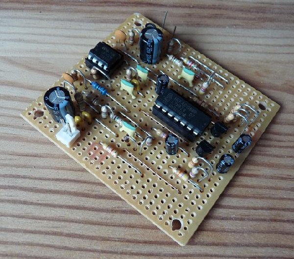
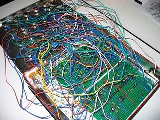
I've built the WSG (the new version with filter) on eurocard prints.
2 of them.
... and it works...
Sorry if my english isn't correct
| Description: |
|
| Filesize: |
40.84 KB |
| Viewed: |
55478 Time(s) |
|
| Description: |
|
| Filesize: |
30.62 KB |
| Viewed: |
55479 Time(s) |

|
| Description: |
|
| Filesize: |
336.93 KB |
| Viewed: |
1266 Time(s) |
| This image has been reduced to fit the page. Click on it to enlarge. |

|
_________________
www.groeneridder.net |
|
|
Back to top
|
|
|
tjookum

Joined: May 25, 2010
Posts: 360
Location: Netherlands
Audio files: 26
|
| Posted: Thu May 27, 2010 5:44 am Post subject:
|
|
|
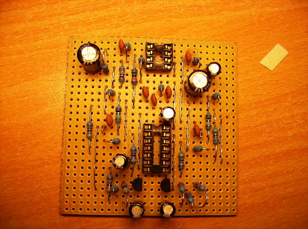
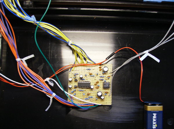
hi there,
First time synth diyer here. Ive been building the WSG using the same stripboard lay-out benuron uses, the improved version from ray's website.
Since it's my first build I took my time and did it slow and rechecked everything twice. But when i switched it on it just produced a very faint fading sound, like something slowly discharging over 5 seconds. I was really dissapointed, a lot of time and care went into building it and I was hoping to be making weird sounds by now. Any thoughts on what it might be?
The things i was confused about on the lay-out:
-The direction of the diodes? did i get it right?
-I added C9 and C10 as described by benuron above, is this correct?
Ive added some pictures, hope it helps... otherwise it's going to be a long night of debugging.
| Description: |
|
| Filesize: |
2.03 MB |
| Viewed: |
953 Time(s) |
| This image has been reduced to fit the page. Click on it to enlarge. |
|
| Description: |
|
| Filesize: |
1.39 MB |
| Viewed: |
988 Time(s) |
| This image has been reduced to fit the page. Click on it to enlarge. |
|
|
|
|
Back to top
|
|
|
tjookum
Joined: May 25, 2010
Posts: 360
Location: Netherlands
Audio files: 26
|
| Posted: Fri May 28, 2010 6:31 am Post subject:
|
|
|
DOH!
After rechecking all the resistor value's, panel wiring and a good night of sleep I just found out i ordered and placed the wrong caps. 100 pF and 22 pF just wont do...lol. Well, at least I learned to check the value's of all components before soldering  . .
My new MKS2 caps in correct value's will be arriving tomorrow, hopefully i didn't damage the IC's and everything is still fine. When I finish this badboy I'll post some pictures. |
|
|
Back to top
|
|
|
squash
Guest
|
Posted: Thu Jul 08, 2010 2:47 pm Post subject:
 2 days of soldering and £40 later, no noise :( 2 days of soldering and £40 later, no noise :( |
|
|
Hi everyone,
I really hope this will get a response at some point as I noticed this thread is quite old...
Ive basically bought and soldered the parts for a WSG made to andrew sharp's stripboard layout, but when i turn it on theres no noise!! when i turn it off (and if im touching a component for a static noise) the static noise kind of phases as the circuit discharges.
This is a first electronics project for me, and as i love the idea of analogue sound equipment, I was really hoping to get some results!
Ill post pictures, but I think these are some of the faults i may have...
in place of the two 1uf capacitors, I am using one 2.2uf 60V and one 1uf 450V capacitor (maplin were out of stock of the one that was reccomended!) (also, when the 450V capacitor is bypassed, it makes no difference)
I have wired the rot pots direct to where it is marked on the stripboard diagram - (you will see from the pictures i will post) am i supposed to follow the very complicated panel wiring scheme?
I have got a chip mounting piece for the longer chip which is one part too long - i doubt this will make a difference though?
Then one time when i turned it on, and left it on for a while, trying to tap audio out of different places in the circuit, i smelt burning, and burnt myself on the 8 pin microchip - will it be completely toasted now?
(Pictures listed below)
Any help would be huuuugely appreciated, any help at all
thanks alot!
Serin K
| Description: |
|
| Filesize: |
734.64 KB |
| Viewed: |
945 Time(s) |
| This image has been reduced to fit the page. Click on it to enlarge. |

|
| Description: |
|
| Filesize: |
547.7 KB |
| Viewed: |
1011 Time(s) |
| This image has been reduced to fit the page. Click on it to enlarge. |

|
|
|
|
Back to top
|
|
|
tjookum
Joined: May 25, 2010
Posts: 360
Location: Netherlands
Audio files: 26
|
| Posted: Fri Jul 09, 2010 2:46 am Post subject:
|
|
|
hi squash! welcome to the world of analog electronics!
The WSG is a great first build and I had a good time building it, but as you can see above it's really easy to miss something and get really confused really fast.
Im no expert but I'll try to help you out here.
| Quote: | in place of the two 1uf capacitors, I am using one 2.2uf 60V and one 1uf 450V capacitor (maplin were out of stock of the one that was reccomended!) (also, when the 450V capacitor is bypassed, it makes no difference)
|
Not sure about this one, I believe these aren't critical for the sound. But after trying everything else you might want to get some new ones and try it.
| Quote: | | I have wired the rot pots direct to where it is marked on the stripboard diagram - (you will see from the pictures i will post) am i supposed to follow the very complicated panel wiring scheme? |
No, if you used the schematic unclekrunkus posted on the first page you wired them up exactly as they should be, you might want to switch around wires to change the turning direction of the pots.
| Quote: | I have got a chip mounting piece for the longer chip which is one part too long - i doubt this will make a difference though?
|
No that's fine.
| Quote: | | Then one time when i turned it on, and left it on for a while, trying to tap audio out of different places in the circuit, i smelt burning, and burnt myself on the 8 pin microchip - will it be completely toasted now? |
Not 100% sure, but if you smell burning it probably is burning  . Try annother chip, just to be sure. . Try annother chip, just to be sure.
Before you do anyhting else, replace the caps(maybe you can get some out of an old electrical appliance) and double check all the components on the board for their correct placement and value(1uF=1000nF).
_________________
There he goes. One of God's own prototypes. A high-powered mutant of some kind never even considered for mass production. Too weird to live, and too rare to die.
Hunter S. Thompson
movies
noise |
|
|
Back to top
|
|
|
blue hell
Site Admin

Joined: Apr 03, 2004
Posts: 24670
Location: The Netherlands, Enschede
Audio files: 330
G2 patch files: 320
|
| Posted: Fri Jul 09, 2010 3:58 am Post subject:
Re: 2 days of soldering and £40 later, no noise :( |
|
|
| squash wrote: | | Hi everyone, |
Hmm hi squash ... your 2nd post, the one about wedding dresses, was not very much appreciated and I deleted it ... also your account has been locked as either it got cracked or you are the spammer yourself ... please contact an admin to get things sorted out.
_________________
Jan
also .. could someone please turn down the thermostat a bit.

9 3 4 .. erm .. not 13 then? .. hmm, ah eight! .. yeah yeah as in 8647 .. 47 is an 88 .. pwew .. numbles! |
|
|
Back to top
|
|
|
-minus-
Joined: Oct 26, 2008
Posts: 787
Audio files: 13
|
| Posted: Fri Jul 09, 2010 4:18 am Post subject:
|
|
|
...and I was just about to help squash with his WSG problems!
It looks like some capacitors are missing and some resistors are in the wrong spot... actually, it looks like there are a few components wrong here... if you are going off the Krunkus strip board, I'd suggest checking that everything is in exactly the right place on your board. You need to follow the diagram religiously pretty much to get it to work... |
|
|
Back to top
|
|
|
urbanspaceman
Joined: Feb 26, 2008
Posts: 78
Location: italy
|
| Posted: Fri Jul 09, 2010 4:47 am Post subject:
|
|
|
@Pascal
Pascal i have two question on your double wsg.
1. Where can I find the complete project (with filter), with the list of components?
2. What kind of stripboard you used?
tnx |
|
|
Back to top
|
|
|
squash2
Joined: Jul 09, 2010
Posts: 5
Location: England
|
Posted: Fri Jul 09, 2010 7:59 am Post subject:
 Help! Help! |
|
|
I thought you were joking about the wedding dress spam thing, but my first account has been de-activated! I know nothing about that, and it is impossible anyone could have got to my computer - now im worried i have some sort of virus :S
(how should i have contacted an admin with out making another account?)
anyway, thanks for the feedback, but i am pretty sure all the components are there and in the right place, it may just look completely wrong due to the angle of the picture and the way i have wired it - for example some resistors's wires fold back under themselves to get to the correct hole.
one other problem i may have had was that two of the capacitors needed, that were meant to be 20nf, were supplied from maplin as 20pf, so i used them instead... i have ordered the correct ones though.
Serin |
|
|
Back to top
|
|
|
squash2
Joined: Jul 09, 2010
Posts: 5
Location: England
|
| Posted: Fri Jul 09, 2010 8:05 am Post subject:
|
|
|
Oh no! i have also just realised that I have been using the diagram and parts list off the original WSG community page...
is there a parts list that goes with the diagram on the first page?
thanks in advance.
Serin |
|
|
Back to top
|
|
|
blue hell
Site Admin
Joined: Apr 03, 2004
Posts: 24670
Location: The Netherlands, Enschede
Audio files: 330
G2 patch files: 320
|
| Posted: Fri Jul 09, 2010 11:53 am Post subject:
Re: Help! |
|
|
| squash2 wrote: | I thought you were joking about the wedding dress spam thing, but my first account has been de-activated! I know nothing about that, and it is impossible anyone could have got to my computer - now im worried i have some sort of virus :S
(how should i have contacted an admin with out making another account?) |
there is an email address ... somewhere ... and no it was no joke .. maybe your password was guessed or something? (such wouldn't be the 1st time here)
_________________
Jan
also .. could someone please turn down the thermostat a bit.
9 3 4 .. erm .. not 13 then? .. hmm, ah eight! .. yeah yeah as in 8647 .. 47 is an 88 .. pwew .. numbles! |
|
|
Back to top
|
|
|
-minus-
Joined: Oct 26, 2008
Posts: 787
Audio files: 13
|
| Posted: Fri Jul 09, 2010 5:07 pm Post subject:
|
|
|
What I think you should do squash2 is:
Check the stripboard diagram on page 1 of this thread. Make sure the back of your board is correct. Have you made ALL of the cut marks and in the right place? Are any of the cuts not done properly?
Check the list of components on Page 1. This could be one of your problems, which it looks like you have identified yourself.
Make sure ALL of the components are of the correct value and the correct place. It looks like you have run jumpers further than needed, then run others back. I think if you start deviating from the plan or move things across one hole or shuffle things around, you could run into problems.
Once you have checked all this and are sure it is right, you should check all your soldering. Make sure you haven't bridged any of the stripboard tracks. Look out for dry solder joints.
Make sure your IC's are inserted correctly and there are no legs bent over and not inserted in the sockets. *You may need to replace the IC which got hot. Don't turn the device on though until you check all of the other things, or you may fry another one! Make sure the IC's are the right way around. (Yours look ok)
Check the wiring to the pots. Is it joined to the board in the right places?
Basically, you need to make sure you follow the diagram EXACTLY for the greatest chance of success. Also, do it as NEATLY as possible. The WSG is a great little device! I know you'll love it once it works for you!
Hope this helps. Good luck! |
|
|
Back to top
|
|
|
squash2
Joined: Jul 09, 2010
Posts: 5
Location: England
|
| Posted: Sat Jul 10, 2010 5:49 pm Post subject:
Thanks :) |
|
|
Thanks for the feed back everyone
Basically, what ive decided to do, is just re order the cheap parts, i.e. everything that goes on the circuit board and re use the expensive ones, such as the rot pots etc. I think im also going to get a much better soldering iron, as the one i was using was rediculously big for the job.
Ill let you know how it goes
Thanks,
Squash |
|
|
Back to top
|
|
|
|

 Forum index » DIY Hardware and Software » MusicFromOuterSpace.com designs by Ray Wilson