| Author |
Message |
fonik

Joined: Jun 07, 2006
Posts: 3950
Location: Germany
Audio files: 23
|
 Posted: Sat Jun 16, 2007 3:11 am Post subject: Posted: Sat Jun 16, 2007 3:11 am Post subject:
|
  |
|
| bblaze wrote: | | So.. I got my expressPCB Up and going! |
you talk about the layout i did months ago? that would be great. i never built it or even checked it for errors! it was just for fun...
_________________

cheers,
matthias
____________
Big Boss at fonitronik
Tech Buddy at Random*Source |
|
|
Back to top
|
|
 |
bblaze
Joined: Jun 03, 2007
Posts: 8
Location: durham, nc usa
Audio files: 1
|
| Posted: Sat Jun 16, 2007 7:20 am Post subject:
|
|
|
hahahaha.. ya.. i spent the $60 for 3 boards.. the first one i botched and got halfway working.. didn't want to trouble shoot it much more.. the 2nd one works great.. gonna modify it a bit and test for buildin gthe 3rd one..  |
|
|
Back to top
|
|
|
fonik
Joined: Jun 07, 2006
Posts: 3950
Location: Germany
Audio files: 23
|
| Posted: Sat Jun 16, 2007 2:00 pm Post subject:
|
|
|
that's realy great. wished i had the same luck with the super controller which i triple checked! . hooked the prototype up and NOTHING worked. i then discovered that the transistors were rotated by 180deg. turned them and still nothing works so i will have a jolly good time of troubleshooting next week...
_________________
cheers,
matthias
____________
Big Boss at fonitronik
Tech Buddy at Random*Source |
|
|
Back to top
|
|
|
Dan Lavin

Joined: Nov 09, 2006
Posts: 649
Location: Spring Lake, Mi, USA
Audio files: 21
|
| Posted: Sat Jun 16, 2007 5:40 pm Post subject:
|
|
|
Fonik,
Just a suggestion, but you could use the folks on this forum to help check the layout. If 2 heads are better than one and the more the merrier, etc.....
Having stated this, I won't be able to assist as I head out on vacation for a week in the woods with 30+ Boy Scouts! But if you're still out of luck in a week, let me know. I've laid out many pcb's over the years and am willing to assist. Sometimes the mistakes are obvious to someone who hasn't spend hours staring at it already. Just a thought... |
|
|
Back to top
|
|
|
goldenechos
Joined: Jun 06, 2007
Posts: 201
Location: Marshall, NC
Audio files: 1
|
| Posted: Sun Jun 17, 2007 7:58 am Post subject:
|
|
|
| State Machine wrote: | | Quote: |
Nice looking board - is the same manufacturer as the SN-Voice? That was one nice board.... |
Sure they will !! 
Double Sided
Silk Screened
Solder Mask
Standard Connector Footprints
Bill |
I REALLY APPRECIATE THESN-VOICE BOARDS.
HOWEVER I found the layout to be confusing as the Resistor and Cap numbers followed no discernable pattern making parts placement time consuming.
Also, what is the increase in cost to have the boards tinned? I had to use a flux pen on every hole in order to get good joints on both sides.
Again, I REALLY APPRECIATE THE BOARDS, well worth the money spent.
TR |
|
|
Back to top
|
|
|
State Machine
Janitor


Joined: Apr 17, 2006
Posts: 2810
Location: New York
Audio files: 24
|
| Posted: Sun Jun 17, 2007 7:24 pm Post subject:
|
|
|
| Quote: | I REALLY APPRECIATE THESN-VOICE BOARDS.
HOWEVER I found the layout to be confusing as the Resistor and Cap numbers followed no discernable pattern making parts placement time consuming.
|
Thanks. As for the layout, I kept the same references for the resistors and capacitors as Thomas Henry intended. This way if anyone had parts for the kit and wanted a PCB for it, they could use the parts they owned. I figured it would be less confusing. Sorry .......
| Quote: | | Also, what is the increase in cost to have the boards tinned? I had to use a flux pen on every hole in order to get good joints on both sides. |
Right now, I am not able to get the board tinned so you will need to use an RMA flux to get good topside flow for my boards. Make sure the iron is clean and set it to about 750 degrees F. You probably know this of course. Put a drop of flux and preheat the pad and you should be good to go! You will have to remove the flux when you are done using a flux removal solvent or just alcohol.
| Quote: | | Again, I REALLY APPRECIATE THE BOARDS, well worth the money spent. |
Thanks for your feedback. I will find out if I can get future boards tinned to make the soldering easier for everyone. That is a very good idea and one I will see about for sure. Again, thanks so much.
Bill |
|
|
Back to top
|
|
|
Thomas_Henry
Joined: Jul 24, 2009
Posts: 170
Location: N. Mankato, MN
Audio files: 3
|
| Posted: Mon Aug 10, 2009 9:09 pm Post subject:
|
|
|
Hi gang,
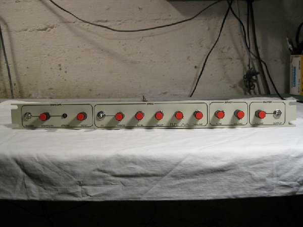
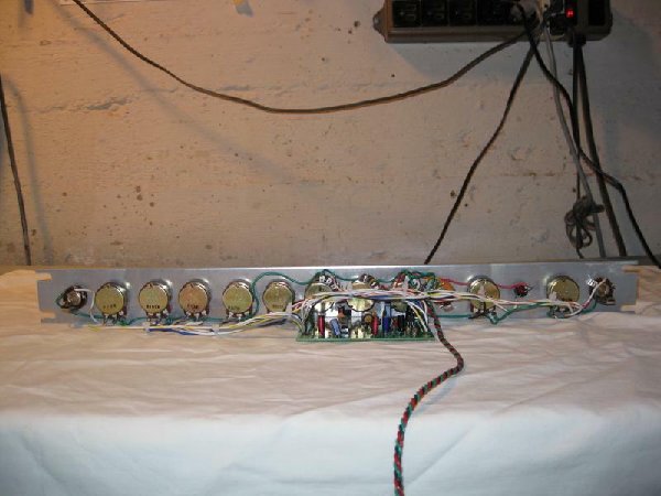
Since things didn't work out this summer for getting six new projects out the door, I decided to catch up on my backlog of old things. Among them was my own hard copy of the UD-1. (My previous version had lived only on a breadboard).
Here's some pictures of it.
Thomas Henry
| Description: |
|
| Filesize: |
46.2 KB |
| Viewed: |
999 Time(s) |
| This image has been reduced to fit the page. Click on it to enlarge. |
|
| Description: |
|
| Filesize: |
48.69 KB |
| Viewed: |
954 Time(s) |
| This image has been reduced to fit the page. Click on it to enlarge. |
|
|
|
|
Back to top
|
|
|
vtl5c3
Joined: Sep 08, 2006
Posts: 425
Location: PDX
Audio files: 13
|
| Posted: Wed Mar 31, 2010 11:17 am Post subject:
|
|
|
| Quick question: can the 500K pots be substituted with 1M? |
|
|
Back to top
|
|
|
State Machine
Janitor
Joined: Apr 17, 2006
Posts: 2810
Location: New York
Audio files: 24
|
| Posted: Wed Mar 31, 2010 3:50 pm Post subject:
|
|
|
| Quote: | | Quick question: can the 500K pots be substituted with 1M? |
Your referring to the BLEND and DECAY potentiometers. You should be able to do this without any problems. In fact, for the decay, that's the value I used (1M) for my module since I liked the ability to have longer decay times. The blend should not be adversely affected either going to a 1M.
You may want to stick with LINEAR (B Type) potentiometers though as I did not see mention of response 
BTW, have you seen the Quad Bass++ circuit boards? Four Bass /Tom voices on a single circuit board.
http://electro-music.com/forum/topic-39402.html&postorder=asc
Bill |
|
|
Back to top
|
|
|
vtl5c3
Joined: Sep 08, 2006
Posts: 425
Location: PDX
Audio files: 13
|
| Posted: Sat Apr 10, 2010 12:58 pm Post subject:
|
|
|
Thank you. That's good to know, since I already have a bunch of 1M pots on hand.
Another question: I have a schematic for mods to the UD-1, including adding a volume decay pot, peak limit resistor and lower pitch cap. I cannot find the source for that. Can anyone point me to it? I'm guessing there's some notes that go with it, which I would like to review. |
|
|
Back to top
|
|
|
State Machine
Janitor
Joined: Apr 17, 2006
Posts: 2810
Location: New York
Audio files: 24
|
| Posted: Sat Apr 10, 2010 2:37 pm Post subject:
|
|
|
| Quote: | | including adding a volume decay pot, peak limit resistor and lower pitch cap. I cannot find the source for that. Can anyone point me to it? I'm guessing there's some notes that go with it, which I would like to review. |
Are there any values or other specifications associated with your present notes? I could help more with that information.
Bill |
|
|
Back to top
|
|
|
vtl5c3
Joined: Sep 08, 2006
Posts: 425
Location: PDX
Audio files: 13
|
|
|
Back to top
|
|
|
Adam-V

Joined: Jan 29, 2007
Posts: 300
Location: Australia
Audio files: 1
|
| Posted: Wed Jul 28, 2010 4:12 am Post subject:
|
|
|
Hi Guys,
Finally got around to assembling one of my UD-1s and it works a treat but when the decay and the sweep are turned up, the pitch is a little high for my liking. If I was to disconnect the ground side of R1 and connect it to -15V instead, would this have any adverse consequences? I'd like the Initial pot to be able to counteract the higher pitch caused by the above mentioned settings.
Cheers,
Adam-V
_________________
Digitalis Effect | Fractured Symmetry (www.spiralsect.com) |
|
|
Back to top
|
|
|
Adam-V
Joined: Jan 29, 2007
Posts: 300
Location: Australia
Audio files: 1
|
| Posted: Sun Aug 01, 2010 6:23 pm Post subject:
|
|
|
| Adam-V wrote: | Hi Guys,
Finally got around to assembling one of my UD-1s and it works a treat but when the decay and the sweep are turned up, the pitch is a little high for my liking. If I was to disconnect the ground side of R1 and connect it to -15V instead, would this have any adverse consequences? I'd like the Initial pot to be able to counteract the higher pitch caused by the above mentioned settings.
Cheers,
Adam-V |
Anybody???
Cheers,
Adam-V
_________________
Digitalis Effect | Fractured Symmetry (www.spiralsect.com) |
|
|
Back to top
|
|
|
bblaze
Joined: Jun 03, 2007
Posts: 8
Location: durham, nc usa
Audio files: 1
|
| Posted: Thu Sep 20, 2012 6:53 am Post subject:
|
|
|
| cracked my ud-1 open a few days ago for some tweaking.. Any chance you still have the PCB image around still? I can't access it here |
|
|
Back to top
|
|
|
bblaze
Joined: Jun 03, 2007
Posts: 8
Location: durham, nc usa
Audio files: 1
|
|
|
Back to top
|
|
|
diablojoy

Joined: Sep 07, 2008
Posts: 809
Location: melbourne australia
Audio files: 11
|
| Posted: Tue Feb 05, 2013 1:36 am Post subject:
|
|
|
So i finally got round to finishing my first UD-1
pitch seemed way too high for a tom sound
up around 5Khz for its lowest initial setting- weird
checked everything C8 value, initial voltage,
voltages to the LM566 all seemed fine
even swapped the LM566
ended up trying a few different values in parallel with C8
which lowered the pitch ok
now the original value of C8 is .022uf according to the BOM and schematic
I ended up with 1uf to get down to a reasonable floor tom sound
and not a bad high rack tom sound with the initial pot all the way clockwise
I certainly dont get as low a freq as Bblazes sample
It all seems to be working fine but really that is a massive difference in cap values to get it to there.
any idea's anyone ?
I have another 3 yet to complete , just need to finish panel wiring
so I guess we shall see if they work out similar.
_________________
In an infinite universe one might very well
ask where the hell am I
oh yeah thats right the land of OZ
as good an answer as any |
|
|
Back to top
|
|
|
elmegil

Joined: Mar 20, 2012
Posts: 2179
Location: Chicago
Audio files: 16
|
| Posted: Tue Feb 05, 2013 7:35 am Post subject:
|
|
|
| Could it be that there's a charging resistor error? I would think a 10k instead of a 100k, for example, would behave similarly.... |
|
|
Back to top
|
|
|
diablojoy
Joined: Sep 07, 2008
Posts: 809
Location: melbourne australia
Audio files: 11
|
| Posted: Tue Feb 05, 2013 1:53 pm Post subject:
|
|
|
one of the first things i checked was the resistor values off pin 6
I even lifted one side and metered them directly.
I have a few tubes of LM566 i must go through and check them all as well
some are obviously pulls , some look possibly fake a few look NOS
i shall see if this highlights some variance
the one i have going is working nice with the odd C8 value , i will wire up a second and compare
_________________
In an infinite universe one might very well
ask where the hell am I
oh yeah thats right the land of OZ
as good an answer as any |
|
|
Back to top
|
|
|
AlasdairMoons

Joined: Dec 03, 2011
Posts: 105
Location: East-Belgium
|
|
|
Back to top
|
|
|
prophei

Joined: Jan 27, 2007
Posts: 234
Location: san francisco, ca
Audio files: 4
|
| Posted: Sun May 24, 2015 8:41 pm Post subject:
any information left? |
|
|
Hey Guys...
I just pulled my old SMS UD-1 board out, but no longer have any of the documentation. i have no idea how to wire all the IO. Do the original docs still exist?
Thanks!
prophei |
|
|
Back to top
|
|
|
elmegil
Joined: Mar 20, 2012
Posts: 2179
Location: Chicago
Audio files: 16
|
|
|
Back to top
|
|
|
elmegil
Joined: Mar 20, 2012
Posts: 2179
Location: Chicago
Audio files: 16
|
|
|
Back to top
|
|
|
Appliancide*

Joined: Jul 04, 2007
Posts: 126
Location: Paul lives in a 1920’s film
|
| Posted: Sun Apr 26, 2020 6:24 am Post subject:
|
|
|
Does anyone still have PCBs for this? If not, I might have to try this on perfboard.
_________________
http://appliancide/blogspot.com |
|
|
Back to top
|
|
|
|

 Forum index » DIY Hardware and Software » Thomas Henry designs