| Author |
Message |
Luka

Joined: Jun 29, 2007
Posts: 1003
Location: Melb.
|
 Posted: Fri Aug 24, 2007 8:03 pm Post subject: Posted: Fri Aug 24, 2007 8:03 pm Post subject:
|
  |
|
| Scott Stites wrote: | Hey Luka,
The file is probably still missing after the crash - it needs a bit of correction to the schematic. I may upload it with the note and fix it later, as I'm pretty tied up with getting the proto done.
Also, I can add your name to the seconds list of the Klee - if someone for some reason or other doesn't purchase their reserved boards, then I turn to this list.
It's also possible there could be a second run if there's enough interest.
Cheers,
Scott |
that would be cool, i pm'ed you about this a while back so it would be great, hence me asking peopel on these threads if they were going to pull out. but if it doesnt happen for the first run i think i am hapy to protoboard it. seems like a fun challenge. im still new into this whole game and building on protoboard is a fun challenge. i did it for the baby 10 in my speaknspell, so this should be a good step up
btw. nice sample tim |
|
|
Back to top
|
|
 |
Scott Stites
Janitor


Joined: Dec 23, 2005
Posts: 4127
Location: Mount Hope, KS USA
Audio files: 96
|
| Posted: Fri Aug 24, 2007 9:39 pm Post subject:
|
|
|
Luka - oh, yeah  
Beautiful night-time pic of the Klee, Tim.
I think you're talking about changing a bit, but not reloading to the original position when a bit is removed or added? Yep, that's PIC territory, I'd say. Being limited on the breadboard to pulling wires in and out of the socket to simulate flipping bits, I've mainly progammed patterns either through random input and/or using the bit juggling method for on-the-fly stuff.
There are further bit manipulations that are possible without modification -switching a gate bus with only one switch flipped to it provides a "tap" from the shift registers at that bus' gate output. Say only stage 16 is set to gate bus 3 and is merged. If you patch the Bus 3 gate into the random input, and set the mode to random, that completes the recirculation path in 16X1 mode. This provides a method to further manipulate patterns:
*You can set any switch to the merged gate bus and alter the pattern by tapping from a "shorter" tap.
*You can patch the gate bus gate output to an external logic module and perform manipulation there (add bits, drop bits).
*If you have more than one Klee, you can chain them.
The EM Klee Boards have connectors that provide direct access to the pattern programming bits - PIC add-ons would be a piece of cake. In fact, a computer interface probably wouldn't be too great of a leap of logic, pardon the pun.....
It would have to be third party, though, I'm exhausted
_________________
My Site |
|
|
Back to top
|
|
|
Luka
Joined: Jun 29, 2007
Posts: 1003
Location: Melb.
|
| Posted: Fri Aug 24, 2007 11:34 pm Post subject:
|
|
|
im passing you a beer right now scott
time for a drink |
|
|
Back to top
|
|
|
ringer

Joined: Feb 20, 2007
Posts: 49
Location: montreal
|
| Posted: Sat Aug 25, 2007 5:19 am Post subject:
|
|
|
error, fixed and deleted
Last edited by ringer on Sat Aug 25, 2007 5:26 am; edited 1 time in total |
|
|
Back to top
|
|
|
ringer
Joined: Feb 20, 2007
Posts: 49
Location: montreal
|
| Posted: Sat Aug 25, 2007 5:23 am Post subject:
|
|
|
| THeff wrote: | Thanks Scott, and everybody for the compliments.
Scott, another thing that I thought would be nice is to replace the pattern toggle switches with push buttons that set and reset as you push them. And in addition to the pushbuttons possibly add an option that would automatically load the new pattern when you touch any of the buttons. It would keep the existing pattern the same except change that 1 bit. To do this right will require a PIC and if I get around to it I would like to add another row of sixteen LEDs that would indicate the existing pattern and be updated immediately after pressing a pushbutton. This would make it really nice for adding or subtracting a bit here and there while the sequencer continues to run. I'm not going to tackle this anytime soon!
Tim |
Congratulations on a fine module. I was doing a strip board version, I was done doing all of the links on the 3 boards and then the EM Klee boards were announced, so I put the project aside and decided to wait for the PCB's.
About using bounce switches for the pattern bits, How about using on-off- momentary on switches? I decided these switches would be good for jamming. That way you could use the momentary side and tweak bits on or off for a measure or whatever.
Here is my layout for the EM Klee, it was inspired by Fonik's original layout. It will be going through a revision to add the Invert B and use new halo's around the pots. It is pretty tight but I spaced everything out and transfered a paper to cardboard, punched all of the holes and put the jacks, pots and switches to test the fluidity of of the layout.
Once again, great efforts from all of you.
Cheers,
Ringer
| Description: |
|

Download (listen) |
| Filename: |
klee v2a.bmp |
| Filesize: |
2.25 MB |
| Downloaded: |
772 Time(s) |
|
|
|
Back to top
|
|
|
THeff

Joined: Sep 01, 2006
Posts: 229
Location: Florida
Audio files: 33
|
| Posted: Sat Aug 25, 2007 9:35 am Post subject:
|
|
|
Hi Ringer, Nice Layout! I think your smart waiting for the PCB. Going the perfboard route is tough. It's probably one of the most tedious perfboards I have ever done. When you first look at the schematic spread over several sheets it doesn't look so bad, and then when you try to crunch it all down on one board and interface it with the panel it gets interesting.
When I mentioned using push button switches I should have made it clear that I meant momentary switches. The PIC microcontoller would be responsible for latching or unlatching the bit based on it's previous state. I would also like the PIC to generate a load pattern pulse after the bit (or bits) are set or reset. This way you just press a button (or multiple buttons) and the pattern would change immediately. I have been thinking about it and it could be done easily with one small PIC, (2) 74HC165s to monitor the switches and (2) 74HC565s to drive the LEDs and the pattern bus.
I still have some troubleshooting to do on the load function but don't want to stop playing! |
|
|
Back to top
|
|
|
Scott Stites
Janitor
Joined: Dec 23, 2005
Posts: 4127
Location: Mount Hope, KS USA
Audio files: 96
|
| Posted: Sat Aug 25, 2007 12:19 pm Post subject:
|
|
|
Well, I should point out that the original function of the pattern switches was to serve as a sort of physical memory element. The original Klee had no way of storing the pattern on power down. The pattern switches served as a means to store the pattern, so when it was powered up, one need only load the settings on the pattern switches. Programming and changing the pattern on the fly was more or less the icing on the cake.
Using momentary switches will present you with two challenges to overcome: one would be storing the pattern on power down. I suppose if the pic has a memory element/back up battery, this wouldn't be an issue. The other issue, however, would be keeping track of a sixteen bit pattern as its running. The physical position of the toggles let you know what the pattern is - momentary switches aren't going to tell you that. If you're anything like me, you may soon forget which bit in the pattern is high or low. An additional row of LEDs could do that, too I suppose.
If what you're looking for is a reload of the pattern each time you change the pattern switch, a PIC wouldn't be all that necessary. You could keep the toggle switches, which would keep you updated which bits were high and low at all times. All one would need to do is patch the data from the toggle switches to two 8 bit parity generators. You're either going to be even or odd, whatever pattern you have selected. As soon as you flip a switch, you change from even or odd. The parity generator will develop a signal depending on if its bits are even or odd. You derive a pulse from that, OR the two pulses from the parity generators together, and send the output of the OR to the external load line.
I personally prefer to depend on the load switch to load the pattern - one can load a pattern, and while that's running set up a new pattern, and when the time is right, punch load to load it. Of course, you could still do that - just disable the pulse from the parity generators.
Or you can avoid all of that and just punch "load" at the same time you flip the switch 
Cheers,
Scott
_________________
My Site |
|
|
Back to top
|
|
|
THeff
Joined: Sep 01, 2006
Posts: 229
Location: Florida
Audio files: 33
|
Posted: Sat Aug 25, 2007 3:14 pm Post subject:
 Load Problem Fixed Load Problem Fixed |
|
|
Hi Scott, Well I finally got serious and tracked down my loading problem. It turned out to be two separate things. The first problem was terrible switch bounce. I looked at pin 6 of U2 on the scope and I was probably getting 10-20 bounce pulses for each key press. I tried another switch (different brand) and the results were the same. I finally put a 0.1uF cap across the switch and that fixed it. Now I get one nice clean pulse.
The second problem was my big oops! I completely left out capacitor C12 on the output of the flip flop and input of U2 pin 9. As a result the flip flop was not getting the reset pulse on pin 4, and this caused it to be a set/reset flip flop instead of a monostable. This explains why the clock would start and stop on every other load pulse. Now everything is working very well.
The push button pattern switches would definitely be a lot of work for just a little added convenience. You are right about the memory problem on power-down, and it would require 16 more status LEDs. It is pretty hard to beat the simplicity of the toggle switches. You can probably tell I like PICs and I am always looking for cool applications for them. Now that the load function works perfect the push button idea doesn't seem as attractive. 
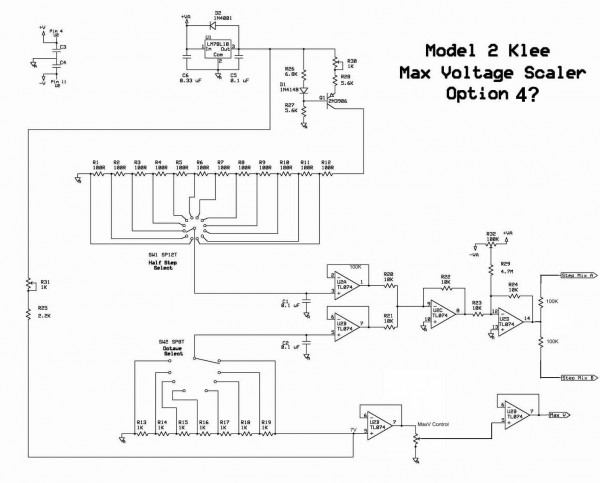
I have done more thinking about the scale voltage multiplication I mentioned several days ago. See if this makes sense: If my MaxV is set to 1 volt, and I have 3 pots set to 0.5 Volts, when they get summed together you will get 1.5 Volts of CV. If I want to raise everything up an octave and set my Octave scale switch to 2 Volts, then each of the pots will now put out 1 Volt for a total 3 Volts CV when summed. To raise the original CV of 1.5 Volts up an Octave it needs to be 2.5 Volts not 3 Volts. This can only be accomplished by inserting the Scale voltage after the pot voltages are summed. This will hold true for the Semi scale voltages as well. Do you see what I mean about the scale voltage getting multiplied? 
Tim |
|
|
Back to top
|
|
|
Scott Stites
Janitor
Joined: Dec 23, 2005
Posts: 4127
Location: Mount Hope, KS USA
Audio files: 96
|
| Posted: Sat Aug 25, 2007 4:31 pm Post subject:
|
|
|
| Quote: | | I want to raise everything up an octave and set my Octave scale switch to 2 Volts. |
Ah, I see what you're getting at.
What you're describing is actually the intended operation. The scale controls set the interval each pot is allowed, so putting them at different settings is going to "expand" the tuning (for want of a better term) rather than move it up linearly. That's why I put such low increments on the EM Klee. The higher ranges are good for small pot increments and more "loose clay" programming, as well as one bit "normal" sequencing, where you want a good four or five octave range (as long as only one pot at a time is giving you that range). The lower increments allow you to max out or set pots to minimum to apply set intervals to the pots. I never intended anything much over 1.5V range to be used in that fashion (nor do I ever do it myself) - I like Klee programming in the higher ranges, because it often allows you to "break the mold".
That last sample I posted in the Super Klee thread was programmed using a range that would easily put the VCOs out of hearing range if they were cranked a whole lot, or if a lot of them were cranked slightly with a high bit density. Exactly what that voltage was - I dunno  I was testing out a higher variable range, but I was feeding it DC that I have yet to measure. I got sidetracked by that sequence (as I'm sure you're becoming aware that the Klee is good at sidetracking a person). I was testing out a higher variable range, but I was feeding it DC that I have yet to measure. I got sidetracked by that sequence (as I'm sure you're becoming aware that the Klee is good at sidetracking a person).
Anyway, all of this is not to say you don't have a good idea - you should be able to get more out of your Klee by attenuating after the interval is set to a certain higher setting. The easiest way to tell is to run your voltage outputs through an attenuator pot, and tune the pot for some division. Just remember a higher bit density/higher interval level is going to "flatten out" the top end as more pots with higher voltage are activated, sending the internal mixer to the rail. To avoid that, you could place the attenuator between the CD4066s and the pots, but that would require sixteen attenuators working in concert. Besides, who's to say if you rail out, that won't add something to what you're doing?
BTW, another very nice addition (easy to add) would be to add offset controls to the voltage outputs (like Ray Wilson does with his S&H circuits). I had a version of the output circuit that included those. I also had a version that allowed an external voltage to be summed to the mixers. Now, that was really handy, and I miss that sometimes. You could patch a keyboard right in, and badda-bim, badda-boom.....
I'm really glad to see you got the load function working! Try sending an LFO to your external load input - that's a gas.
And thank you very much for mentioning the solution to the noisy switch, I'll definitely put that in the arsenal.
Take care,
Scott
_________________
My Site |
|
|
Back to top
|
|
|
THeff
Joined: Sep 01, 2006
Posts: 229
Location: Florida
Audio files: 33
|
|
|
Back to top
|
|
|
Scott Stites
Janitor
Joined: Dec 23, 2005
Posts: 4127
Location: Mount Hope, KS USA
Audio files: 96
|
| Posted: Sat Aug 25, 2007 6:27 pm Post subject:
|
|
|
That looks like a plan - it ought to give you a lot more versatility. Neat idea!
The EM Klee doesn't use the two rotaries, it has a series of lower ranges, and two higher ranges, or one higher range and a variable range (which comes closest to this concept). The purpose of the variable range on the EM Klee is a bit different - the aim of the optional variable range on the EM Klee is to allow the operator to set some other interval than is available on the lower ranges of the rotary switch. Optionally (again) it also allows one to input an external voltage, such as a sequencer, LFO or whatever and let that determine the pot range. You could do the same by putting the +V voltage to the normal input of a jack and the output of the jack to the top of the pot. In that case, you should put a diode in, cathode to ground, on the center tap of the pot so negative voltages don't inadvertently get in and fricasee the CD4066's. Let me know how it turns out, we could add Option 4 (credited to you) into the Model 2 Klee docs.
Give it a spin!
Cheers,
Scott
_________________
My Site |
|
|
Back to top
|
|
|
THeff
Joined: Sep 01, 2006
Posts: 229
Location: Florida
Audio files: 33
|
|
|
Back to top
|
|
|
Scott Stites
Janitor
Joined: Dec 23, 2005
Posts: 4127
Location: Mount Hope, KS USA
Audio files: 96
|
| Posted: Sat Aug 25, 2007 9:58 pm Post subject:
|
|
|

Oh, ma..han...that's cool. I dig it! That's a funky line it's based off of - man, that's set just right. Nice arrangement of the voices. I really like how you're panning the separate voices - I've been wanting to try that, but I'm just literally not set up to do that. You're also getting a nice blend of the voices back and forth. Ain't it funny how with only three control voltages, it seems like you can get a lot more than three things going at a time? The gate bus is partially responsible for that, I suppose.
I don't know if you've experienced it, but for it's sometimes really surprisng when you're setting up a sequence, things sound...eh....but, then you flip that one switch or crank that one pot and things just fall together. Then, sometimes, it depends a lot on what kind of voice you're driving - the pattern stays the same, but you find some attribute of the voice that works well with it.
Cool use of the noise, too. Thanks for sharing this!
That's Klee sequencing.
Now....more!
Take care,
Scott
_________________
My Site |
|
|
Back to top
|
|
|
THeff
Joined: Sep 01, 2006
Posts: 229
Location: Florida
Audio files: 33
|
| Posted: Sat Aug 25, 2007 11:09 pm Post subject:
|
|
|
Thanks Scott, All the credit goes to you and the guys here on EM! I know I keep making suggestions but I've got to tell you this design  of yours is really fun and addictive just the way it is! of yours is really fun and addictive just the way it is!
I was lucky enough to come along and build it after all the design, discussion, and hard work was already done. When I look back through the 25 pages of the "Super Klee" thread I see quite an evolution and it will be great when the PCBs start getting built. I think there will be no end to the creative and unique ways it will be used. You have unleashed the Klee Creature  and you will never be able to get it back in the box! and you will never be able to get it back in the box!
You are absolutely right about small tweaks in the switches and knobs making a huge variation in the sequence. The tip you gave me about flipping the 8x2/16x1 switch randomly while it is clocking is really great.
Thanks again for all of your documentation, tips, and insight. I have built a lot of synth modules this year but the Klee definitely will have the most impact and packs the biggest punch.
Regards,
Tim |
|
|
Back to top
|
|
|
THeff
Joined: Sep 01, 2006
Posts: 229
Location: Florida
Audio files: 33
|
| Posted: Sun Aug 26, 2007 12:49 pm Post subject:
LED Changes |
|
|
Hi all,
Being the hardware centric guy that I am, I made some trivial changes to the LEDs. At first I used all red leds but after playing with the Klee a while I decided it might be easier to keep track of events if I used different colors.
All LEDs are red except fo the following:
1.) Every fourth LED (1st, 5th, 9th, and 13th) are now green.
2.) The Clock LED is blue 
3.) The Master Gate LED is blue.
4.) Bus 1 Gate LED is still red. 
5.) Bus 2 Gate LED is yellow. 
6.) Bus 3 Gate LED is green. 
Regards,
Tim
Not much of of a change but it is a little easier to follow and it looks cool. |
|
|
Back to top
|
|
|
fonik

Joined: Jun 07, 2006
Posts: 3950
Location: Germany
Audio files: 23
|
| Posted: Sun Aug 26, 2007 2:15 pm Post subject:
|
|
|
now i am getting really envious! you both talk about the klee patterns and upload samples... i now wished i had built one one stripboard...
_________________

cheers,
matthias
____________
Big Boss at fonitronik
Tech Buddy at Random*Source |
|
|
Back to top
|
|
|
THeff
Joined: Sep 01, 2006
Posts: 229
Location: Florida
Audio files: 33
|
|
|
Back to top
|
|
|
a.b.o.z.

Joined: Feb 07, 2007
Posts: 351
Location: Zagreb, Croatia
Audio files: 7
G2 patch files: 4
|
Posted: Sun Aug 26, 2007 3:20 pm Post subject:
 |
|
|
whaaaat
omg
omg
omg
omg
omg
omg
omg
this is sooooo cool.
cant wait to solder..i don't like soldering because my back hurts when i sit alot. but anything for klee. wow. just wow. |
|
|
Back to top
|
|
|
Scott Stites
Janitor
Joined: Dec 23, 2005
Posts: 4127
Location: Mount Hope, KS USA
Audio files: 96
|
| Posted: Sun Aug 26, 2007 4:05 pm Post subject:
|
|
|
OMG - you're taking that Klee downtown. I'm reeling here, I truly am. I love this tune (and the name ). I like the arrangement - how it slows down, then comes bopping back like Beaver on his way home from school.
I wish it would have come out earlier today - I was working on a webpage, and had a selection of Klee tunes playing - your two previous posts, some of mine, and iPassengers G2 Klee tune, and just let it loop. It was great how they meshed together to form a body of Kleey otherworldy music.
You don't know what a relief this is for me - my greatest concern was that people would spend all their time and money building Klees, then end up scratching their heads and begin looking for feathers and the rail to put me on. But you've proven to me that it's not an idiosyncrancy - you're already cranking some good solid music.
Thanks again and keep'em coming if you don't mind.
Cheers,
Scott
PS - Cool idea on the LEDs.
_________________
My Site |
|
|
Back to top
|
|
|
THeff
Joined: Sep 01, 2006
Posts: 229
Location: Florida
Audio files: 33
|
| Posted: Sun Aug 26, 2007 5:12 pm Post subject:
|
|
|
Thanks a.b.o.z. and Scott,
I really had a lot of fun making that last sample. I built up the Syntom II, Synbal, and UD-1 a few months ago and have not really used them yet, until today. What a kick! Scott, I predict that you will be sending out for a second batch (or more) of Klee 2 PCBs.
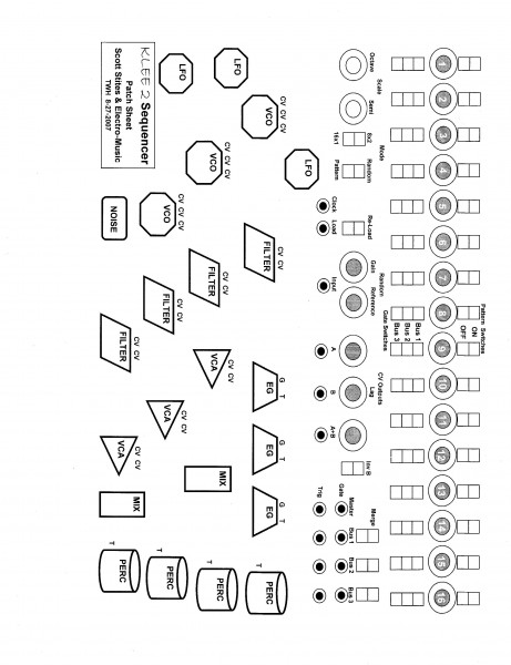
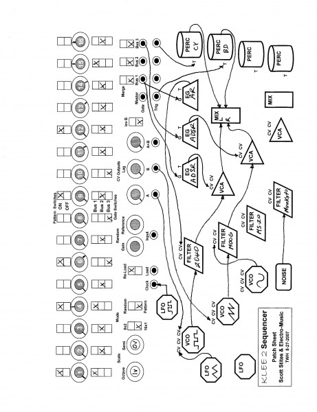
I am going to work on some type of generic Klee patch sheet so that we can easily scribble down the settings of a particular sample. I'm concerned that people will ask me about the setup and I won't remember.
Catch you later,
Tim |
|
|
Back to top
|
|
|
THeff
Joined: Sep 01, 2006
Posts: 229
Location: Florida
Audio files: 33
|
|
|
Back to top
|
|
|
Scott Stites
Janitor
Joined: Dec 23, 2005
Posts: 4127
Location: Mount Hope, KS USA
Audio files: 96
|
| Posted: Mon Aug 27, 2007 10:17 am Post subject:
|
|
|
Hey this is a great idea - I can never remember how my Klee patches were set up (part of that has to do with breadboard spaghetti). I like the arrangement a lot, actually - I've never figured out how to get everything in a coherent arrangement, but that looks pretty good. It would be particularly useful for setting up live sets, too.
I'll have to DL and study it some more.
Cheers,
Scott
_________________
My Site |
|
|
Back to top
|
|
|
Randaleem
Joined: May 17, 2007
Posts: 456
Location: Northern CA, USA
|
| Posted: Mon Aug 27, 2007 12:18 pm Post subject:
|
|
|
Tim,
Looks great!
Perhaps add a bit more space between the Klee and the synth elements below it. That LFO is pretty close to the Klee if you're trying to run patchcord lines around the page.
EDIT: I do understand that it may be so close because you're probably intending it to be feeding the clock input. That is the dual-edged sword of Damocles WRT patch sheets, I think. On the one hand they record. On the other they can tend to direct.
Putting space between and even arranging elements in strange relative positions can spark creativity.
Has anyone else discovered that when you move the modules in your system around, you sometimes find new sounds? That some new paths occur to you that were before left un-noticed?
BTW, Nice demos too!
Randal |
|
|
Back to top
|
|
|
Wild Zebra

Joined: Apr 28, 2005
Posts: 806
Location: Ohio
Audio files: 5
|
| Posted: Mon Aug 27, 2007 1:11 pm Post subject:
|
|
|
I finally checked this post out. Just awesome. Great work. Way to make us all jealous
_________________
"your stripes are killer bro" |
|
|
Back to top
|
|
|
THeff
Joined: Sep 01, 2006
Posts: 229
Location: Florida
Audio files: 33
|
|
|
Back to top
|
|
|
|

 Forum index » DIY Hardware and Software » Klee sequencer