| Author |
Message |
creatorlars

Joined: Nov 26, 2007
Posts: 524
Location: Denton, TX
Audio files: 4
|
 Posted: Wed Dec 17, 2008 11:32 am Post subject: Posted: Wed Dec 17, 2008 11:32 am Post subject:
|
  |
|
| I think UD1 kits & PCBs are still available from sMs. Check the thread in this subforum for details. The Clangora board was self-etched and a huge project, but I think that documentation is still available somewhere here in the forum too. I can reupload if you can't find it. I love the Clangora, especially the separate open/closed hat input/trigger structure. |
|
|
Back to top
|
|
 |
iceowl

Joined: Dec 12, 2008
Posts: 44
Location: Silicon Valley, California
|
| Posted: Wed Dec 17, 2008 4:43 pm Post subject:
|
|
|
Hi all,
My first post to em. Advanced apologies for any internet media / forum culture screwups.
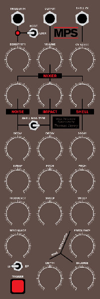
I'm getting into DIY after decades of synthesis love and ownership. I've got my hands on the MPS board, the schematics/parts list from the Thomas Henry site, and enough parts to fill a couple small railroad cars.
As I proceed on my board population quest, I notice I am going to have to trace the schematics to figure out how the pinout on the MTA100 connectors relates to the various pots/switches/jacks.
I have found the Bugbrand panel layout post which also contains a schematic representation of the pinout, but it appears that was done PRE-board manufacture.
Can anyone say if that layout is still valid, or if there's another readily available description of the pinouts? Following the traces on the board and mapping them to the schematics I'm sure is the way true believers in the cause do it. But I'm wondering if there's a lazy man's aid.
Cheers,
Joe |
|
|
Back to top
|
|
|
State Machine
Janitor


Joined: Apr 17, 2006
Posts: 2810
Location: New York
Audio files: 24
|
| Posted: Wed Dec 17, 2008 5:48 pm Post subject:
|
|
|
| Quote: | | Is anyone offering UD1/Clangora/Simmons PCBs? I looked around a month or so ago, but promptly forgot to finish mysearch because of the holidays. |
Yup, creatorlars is correct (thanks) .... I am currently still sourcing UD-1 boards and kits ............
Please have a peek here for the details:
http://electro-music.com/forum/post-128552.html#128552
Thanks,
Bill |
|
|
Back to top
|
|
|
fadeddata
Joined: Dec 27, 2004
Posts: 43
Location: Nashville TN
|
| Posted: Sun Dec 21, 2008 4:03 pm Post subject:
Status LED? |
|
|
I've started designing my front panel and I'm working off of other peoples panels, the schematics, and Scott's original post about the front panel controls. I see on schematic 2 a "Status" LED. Is this the same as the trigger LED? Should it be in close proximity to the Impact section of the front panel?
Thanks all!
-dustin |
|
|
Back to top
|
|
|
fadeddata
Joined: Dec 27, 2004
Posts: 43
Location: Nashville TN
|
| Posted: Sun Dec 21, 2008 9:24 pm Post subject:
Dual Henry MPS |
|
|
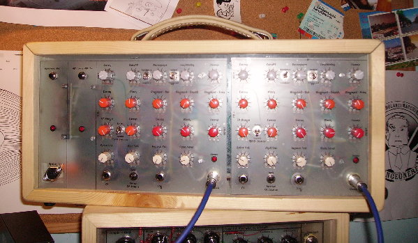
Ok...worked on this tonight. Thoughts?
-dustin
Last edited by fadeddata on Tue Dec 23, 2008 12:19 pm; edited 1 time in total |
|
|
Back to top
|
|
|
tommi

Joined: Dec 05, 2007
Posts: 247
Location: Italy
Audio files: 3
|
| Posted: Mon Dec 22, 2008 3:39 am Post subject:
|
|
|
Hello dustin,
Nice panel. Good choice to have a twin! Much better than a single one. I can confirm this because I just finished to build and test my double mps module (soon I 'll come with a picture). It's GREAT !
It seems you forgot (or you made the choice to leave out) the triggered/locked switch... but it is a great feature for the MPS because it gives infinite decay to all oscillators transforming the MPS in a 4 voice traditional synth.
I also noticed that the resonance pot is in the impact section... this could may be a bit confusing...
| Quote: | Can anyone say if that layout is still valid, or if there's another readily available description of the pinouts? Following the traces on the board and mapping them to the schematics I'm sure is the way true believers in the cause do it. But I'm wondering if there's a lazy man's aid.
|
Hey iceowl,
I assure you that bugbrand's pinouts are true even for the new released boards. The only difference is that j21(optional filter CV) does not exist in the new layout.
cheers, t
_________________
http://soundcloud.com/mister-vommi
http://tideofsound.net |
|
|
Back to top
|
|
|
sduck

Joined: Dec 16, 2007
Posts: 459
Location: Nashville
Audio files: 5
|
| Posted: Mon Dec 22, 2008 9:59 am Post subject:
|
|
|
| Very nice Dustin! And it gives me some impetus to get going on my panel. I've managed to squeeze the whole thing onto a 2u motm style panel, although I haven't got the labeling figured out yet. |
|
|
Back to top
|
|
|
fadeddata
Joined: Dec 27, 2004
Posts: 43
Location: Nashville TN
|
|
|
Back to top
|
|
|
asafnetzer
Joined: Jun 16, 2007
Posts: 112
Location: Israel
|
| Posted: Tue Dec 23, 2008 1:02 pm Post subject:
|
|
|
| Nice panel design, now i'm really sorry for only ordering one pcb |
|
|
Back to top
|
|
|
tommi
Joined: Dec 05, 2007
Posts: 247
Location: Italy
Audio files: 3
|
|
|
Back to top
|
|
|
mosc
Site Admin

Joined: Jan 31, 2003
Posts: 18249
Location: Durham, NC
Audio files: 226
G2 patch files: 60
|
| Posted: Wed Dec 24, 2008 11:49 am Post subject:
|
|
|
Great pics of the gear. Congrats to all who have built this project.
Now, let's hear some music. 
_________________
--Howard
my music and other stuff |
|
|
Back to top
|
|
|
American Gladiator
Joined: May 02, 2007
Posts: 13
Location: USA
|
| Posted: Mon Jan 12, 2009 10:10 am Post subject:
|
|
|
| I am proud to report a successful build on this project. Oh, and it sounds very nice. |
|
|
Back to top
|
|
|
lexvortex

Joined: May 14, 2008
Posts: 155
Location: Toronto
|
|
|
Back to top
|
|
|
Rykhaard
Joined: Sep 02, 2007
Posts: 1290
Location: Canada
|
| Posted: Sun Feb 01, 2009 9:59 am Post subject:
|
|
|
Here's a pic of the 1st of my 2 x MPSes that I completed finally, last night:

She's working beautifully! Many great thanks and respect to Thomas Henry, Scott Stites and everyone else involved with this project.
There're a few more details on it, posted within my Blog - URL below. |
|
|
Back to top
|
|
|
State Machine
Janitor
Joined: Apr 17, 2006
Posts: 2810
Location: New York
Audio files: 24
|
|
|
Back to top
|
|
|
Rykhaard
Joined: Sep 02, 2007
Posts: 1290
Location: Canada
|
| Posted: Sun Feb 01, 2009 2:57 pm Post subject:
|
|
|
Thanks much Bill! Really glad that you like that pic THAT much! 
Looking at the close-up of the "drummer's" head - 2 months since I drew the panel, I think mostly likely, that it were meant to be a tube. A mohawk though, with me in life thoughts, is very possible. Heh. |
|
|
Back to top
|
|
|
discoslut
Joined: Dec 04, 2008
Posts: 6
Location: Netherlands
|
|
|
Back to top
|
|
|
Rykhaard
Joined: Sep 02, 2007
Posts: 1290
Location: Canada
|
| Posted: Wed Feb 11, 2009 10:25 am Post subject:
|
|
|
If I'm not mistaken, the problem is with your MC74HC4046AN. The HC version of the 74 hundred CMOS series is limited to a -0.5 to +7V operating range. (If I'm not mistaken again, the C only series of 7400's will operate up to +15 or +1 . .
Stick with the standard CD4046 series and you'll be fine up to +20V. |
|
|
Back to top
|
|
|
lexvortex
Joined: May 14, 2008
Posts: 155
Location: Toronto
|
Posted: Wed Feb 11, 2009 11:01 am Post subject:
Subject description: Manual trigger |
|
|
Hi,
I would like to be able to manually trigger the MPS, how can I do this?
Thanks,
Dave |
|
|
Back to top
|
|
|
Uncle Krunkus
Moderator

Joined: Jul 11, 2005
Posts: 4761
Location: Sydney, Australia
Audio files: 52
G2 patch files: 1
|
| Posted: Wed Feb 11, 2009 2:26 pm Post subject:
|
|
|
I reckon the best way would be with one of Ray's drum trigger circuits, they put out a trigger and a CV you can plug straight into the MPS.
BTW Rykhaard's right, use the standard CD4046 instead.
_________________
What makes a space ours, is what we put there, and what we do there. |
|
|
Back to top
|
|
|
discoslut
Joined: Dec 04, 2008
Posts: 6
Location: Netherlands
|
| Posted: Wed Feb 11, 2009 7:26 pm Post subject:
|
|
|
| Thanks for the quick response guys! I'll try that. |
|
|
Back to top
|
|
|
lexvortex
Joined: May 14, 2008
Posts: 155
Location: Toronto
|
| Posted: Thu Feb 12, 2009 10:46 am Post subject:
|
|
|
Thanks
| Quote: | | I reckon the best way would be with one of Ray's drum trigger circuits, they put out a trigger and a CV you can plug straight into the MPS. |
But I think that is for using a drum head, which is a cool idea but I just want to have a push button on the panel . Something like triggering an envelope generator in an ADSR. I was thinking maybe taking a voltage from the +15V rail and using an SPST momentary switch to the trigger in, but I don't know if that is too much voltage or if I should put a resistor in series...  . Any help would be much appreciated . Any help would be much appreciated
Thanks,
Dave |
|
|
Back to top
|
|
|
Uncle Krunkus
Moderator
Joined: Jul 11, 2005
Posts: 4761
Location: Sydney, Australia
Audio files: 52
G2 patch files: 1
|
| Posted: Thu Feb 12, 2009 2:56 pm Post subject:
|
|
|
I'd put a momentary switch from the junction of R45/36 to the socket side of C3. This way the "sensitivity" pot will still control how big the pulse is.
_________________
What makes a space ours, is what we put there, and what we do there. |
|
|
Back to top
|
|
|
lexvortex
Joined: May 14, 2008
Posts: 155
Location: Toronto
|
| Posted: Fri Feb 13, 2009 12:51 am Post subject:
|
|
|
Great!! I'll try that out
 I really appreciate your help I really appreciate your help
Dave |
|
|
Back to top
|
|
|
discoslut
Joined: Dec 04, 2008
Posts: 6
Location: Netherlands
|
| Posted: Sat Feb 14, 2009 9:19 am Post subject:
|
|
|
| Rykhaard wrote: | If I'm not mistaken, the problem is with your MC74HC4046AN. The HC version of the 74 hundred CMOS series is limited to a -0.5 to +7V operating range. (If I'm not mistaken again, the C only series of 7400's will operate up to +15 or +1.
Stick with the standard CD4046 series and you'll be fine up to +20V. |
Thanks Rykhaard, the IC has been replaced and works well!
I do have another question.
I noticed that the shell and impact pitch seems to be slightly affected by all the decay pots (in the lower positionsof the decay pots). Is that normal? |
|
|
Back to top
|
|
|
|

 Forum index » DIY Hardware and Software » Thomas Henry designs