| Author |
Message |
vtl5c3
Joined: Sep 08, 2006
Posts: 425
Location: PDX
Audio files: 13
|
|
|
Back to top
|
|
 |
Funky40
Joined: Sep 24, 2005
Posts: 875
Location: Swiss
Audio files: 1
G2 patch files: 5
|
 Posted: Sat Jul 11, 2009 6:03 pm Post subject: Posted: Sat Jul 11, 2009 6:03 pm Post subject:
|
  |
|
wow, thanks alot !
And i wish you good recovery
ff |
|
|
Back to top
|
|
|
ericcoleridge

Joined: Jan 16, 2007
Posts: 889
Location: NYC
|
| Posted: Sat Jul 11, 2009 7:35 pm Post subject:
|
|
|
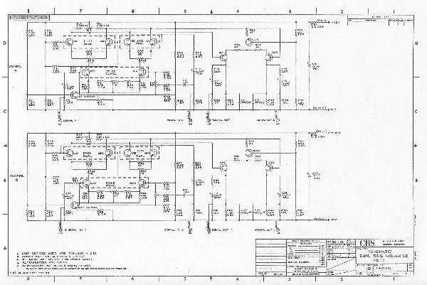
| Quote: | | OK, Kiddies! Here's another Buchla pcb layout for you to play with. |
!!!
The schematic was here. The page is not opening for me at the moment 
Maybe he's up-loading some more schematics onto the site  |
|
|
Back to top
|
|
|
vtl5c3
Joined: Sep 08, 2006
Posts: 425
Location: PDX
Audio files: 13
|
|
|
Back to top
|
|
|
vtl5c3
Joined: Sep 08, 2006
Posts: 425
Location: PDX
Audio files: 13
|
| Posted: Thu Jul 23, 2009 10:17 am Post subject:
|
|
|
Quick update: I soldered most of the components to my PCB last night. I'm waiting for mouser to send me a replacement trimmer, since they sent me a broken one. I hope to be able to test it by the end of next week.
R. |
|
|
Back to top
|
|
|
ericcoleridge
Joined: Jan 16, 2007
Posts: 889
Location: NYC
|
| Posted: Thu Jul 23, 2009 12:37 pm Post subject:
|
|
|
This is in my que. Thanks again for posting.
I drew layouts for the 106 mixer and 170 Preamp, for practice, and because they were easy. I need to re-do them on graph paper or some program. What do you use for your layouts (like this 111)? |
|
|
Back to top
|
|
|
vtl5c3
Joined: Sep 08, 2006
Posts: 425
Location: PDX
Audio files: 13
|
| Posted: Thu Jul 23, 2009 1:55 pm Post subject:
|
|
|
I usually start in Photoshop 5.5, using the line tool. I then finish up in Photoshop CS2. Not an ideal workflow, but I learned it when that was the best I had to work with. I'd like to learn Eagle or some other PCB layout program, but you know how that goes....
| ericcoleridge wrote: | This is in my que. Thanks again for posting.
I drew layouts for the 106 mixer and 170 Preamp, for practice, and because they were easy. I need to re-do them on graph paper or some program. What do you use for your layouts (like this 111)? |
|
|
|
Back to top
|
|
|
ericcoleridge
Joined: Jan 16, 2007
Posts: 889
Location: NYC
|
| Posted: Thu Jul 23, 2009 2:22 pm Post subject:
|
|
|
| vtl5c3 wrote: | I'd like to learn Eagle or some other PCB layout program, but you know how that goes....
|
Yeah, I'd almost rather use Eagle and/or some other free layout program; least that way I'd have a better chance of getting the spacing correct. But I don't have enough memory left on my ancient abacus to download them! Very frustrating. Fortunately, I have Illustrator and Photoshop already installed; I'll give it another try. I want to ultimately tackle the 140 and 180, then possibly the 295... |
|
|
Back to top
|
|
|
vtl5c3
Joined: Sep 08, 2006
Posts: 425
Location: PDX
Audio files: 13
|
| Posted: Fri Jul 24, 2009 8:03 am Post subject:
|
|
|
Hold off on the 180, since I already have a layout for that. I'll clean it up and post it before long.
| ericcoleridge wrote: | | vtl5c3 wrote: | I'd like to learn Eagle or some other PCB layout program, but you know how that goes....
|
Yeah, I'd almost rather use Eagle and/or some other free layout program; least that way I'd have a better chance of getting the spacing correct. But I don't have enough memory left on my ancient abacus to download them! Very frustrating. Fortunately, I have Illustrator and Photoshop already installed; I'll give it another try. I want to ultimately tackle the 140 and 180, then possibly the 295... |
|
|
|
Back to top
|
|
|
Fernando

Joined: Dec 30, 2006
Posts: 286
Location: Barcelona & Emporda, Spain
|
| Posted: Mon Jul 27, 2009 9:00 am Post subject:
|
|
|
nice and inspiring Romeo! as usual
any sound yet?
it is a discrete four quadrant multiplier? |
|
|
Back to top
|
|
|
vtl5c3
Joined: Sep 08, 2006
Posts: 425
Location: PDX
Audio files: 13
|
| Posted: Mon Jul 27, 2009 9:33 am Post subject:
|
|
|
Hi Fernando,
It's all soldered and wired to a front panel. I'm just waiting for a replacement trimpot from Mouser. I hope to have it running by the weekend, providing that there aren't errors in the schematics. As far as I can tell, it is a four quadrant multiplier.
| Fernando wrote: | nice and inspiring Romeo! as usual
any sound yet?
it is a discrete four quadrant multiplier? |
|
|
|
Back to top
|
|
|
vtl5c3
Joined: Sep 08, 2006
Posts: 425
Location: PDX
Audio files: 13
|
| Posted: Thu Jul 30, 2009 10:03 pm Post subject:
Progress |
|
|
So I've been testing it since last night. Last night it was completely not working. I'm using the new Kobicon 1/8" jacks from mouser and wired everything up incorrectly, because they changed the pinout. On top of that, they are flimsy. I will have to find better jacks.
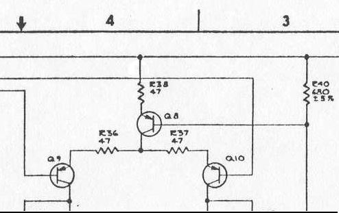
Tonight I made another attempt, this time with the jacks wired correctly. The signal is getting all the way to the bases of the output transistors (Q9 & 10), but not any further. My guess is that R39 & 40 need to be changed since I subbed 2N3906s for the PNPs in the original circuit. They are probably not getting turned on enough to pass the signal through. I will experiment further in the next few days and let you know how it goes.
R. |
|
|
Back to top
|
|
|
vtl5c3
Joined: Sep 08, 2006
Posts: 425
Location: PDX
Audio files: 13
|
| Posted: Fri Jul 31, 2009 10:09 am Post subject:
|
|
|
I think I found the problem. The CBS/Buchla Schematic has an error in it. R38, the 47Ω resistor that goes from Q8's collector to Q10 and the top matched pairs should actually connect to V+. Luckily I have two other versions of this schematic that don't have this error. I'll update the PCB layout ASAP.
R. |
|
|
Back to top
|
|
|
vtl5c3
Joined: Sep 08, 2006
Posts: 425
Location: PDX
Audio files: 13
|
|
|
Back to top
|
|
|
LektroiD

Joined: Aug 23, 2008
Posts: 1019
Location: Scottish Borders
Audio files: 2
G2 patch files: 2
|
| Posted: Sun Dec 19, 2010 8:20 am Post subject:
|
|
|
I'm thinking of building a couple of these but the matched transistors are prohibitively expensive (if available). The diagram posted suggests you can match your own, however the originals are dual monolithic transistors, and by the looks of things these are rather complex designs:
| Quote: | Monolithic Transistor Circuit
A semiconductor body of collector material has a first and second base region diffused into the collector material, and a first and second emitter region diffused into the base regions. A narrow channel of base material connects the two base regions. A metallic coating connects the first emitter region with the second base region. This metallic coating extends over the connecting channel and is situated directly on the surface of the semiconductor body. The first emitter region may be extended into the second base region directly under the metal coating which connects the first emitter with the second base. |
With the above in mind, I have a feeling this can not be replicated with a straight matched pair. Has anyone tried matched 2n3904's in this board?
_________________
LektroiD |
|
|
Back to top
|
|
|
vtl5c3
Joined: Sep 08, 2006
Posts: 425
Location: PDX
Audio files: 13
|
| Posted: Sun Dec 19, 2010 9:42 am Post subject:
|
|
|
My 2 cents: try it!
I'd be surprised if the design didn't work with hand-matched transistors. There's plenty of trimmers to compensate for mismatches. |
|
|
Back to top
|
|
|
tokyomatik

Joined: Jan 20, 2011
Posts: 171
Location: berlin
Audio files: 6
|
| Posted: Thu Feb 23, 2012 10:05 pm Post subject:
|
|
|
| anybody verified if this layout works? |
|
|
Back to top
|
|
|
vtl5c3
Joined: Sep 08, 2006
Posts: 425
Location: PDX
Audio files: 13
|
| Posted: Fri Feb 24, 2012 8:05 am Post subject:
|
|
|
| Worked for me. |
|
|
Back to top
|
|
|
tokyomatik
Joined: Jan 20, 2011
Posts: 171
Location: berlin
Audio files: 6
|
| Posted: Fri Feb 24, 2012 12:35 pm Post subject:
|
|
|
| is it possible to make it work also at +12v ? |
|
|
Back to top
|
|
|
tokyomatik
Joined: Jan 20, 2011
Posts: 171
Location: berlin
Audio files: 6
|
| Posted: Fri Feb 24, 2012 12:43 pm Post subject:
|
|
|
....ehm....and would be possible to listen some samples?  |
|
|
Back to top
|
|
|
ericcoleridge
Joined: Jan 16, 2007
Posts: 889
Location: NYC
|
| Posted: Fri Feb 24, 2012 7:09 pm Post subject:
|
|
|
| tokyomatik wrote: | | ....ehm....and would be possible to listen some samples? |
ehem, he said it sounded like a typical ring modulator. No one else has built this, you'll have to try 12v yourself and see. I'm guessing it will work. |
|
|
Back to top
|
|
|
vtl5c3
Joined: Sep 08, 2006
Posts: 425
Location: PDX
Audio files: 13
|
| Posted: Mon Feb 27, 2012 10:27 pm Post subject:
|
|
|
| I was playing it tonight. It's very old school sounding... similar to the CGS ARRM, maybe.... I'll post some mp3s to demonstrate. |
|
|
Back to top
|
|
|
LektroiD
Joined: Aug 23, 2008
Posts: 1019
Location: Scottish Borders
Audio files: 2
G2 patch files: 2
|
| Posted: Mon Feb 27, 2012 10:38 pm Post subject:
|
|
|
I'm stuck looking for 5.6µF tantalums.. I'm thinking of using 6.8µF tants in their place.
Also I'm using 2n3904/2n3906 throughout.. I'll report back once I have it finished |
|
|
Back to top
|
|
|
vtl5c3
Joined: Sep 08, 2006
Posts: 425
Location: PDX
Audio files: 13
|
| Posted: Tue Feb 28, 2012 8:57 pm Post subject:
audio sample |
|
|
|
|
|
Back to top
|
|
|
LektroiD
Joined: Aug 23, 2008
Posts: 1019
Location: Scottish Borders
Audio files: 2
G2 patch files: 2
|
| Posted: Wed Feb 29, 2012 8:14 am Post subject:
|
|
|
I've just finished this. It works and sounds awesome...
I used 6.8µF Tantalums in place of the 5.6µF Tantalums.
I used 2n3904/2n3906 transistors throughout and none have been matched - as someone mentioned earlier in the thread, there's enough presets to compensate for this.
I'm not sure of the calibration method, but I ran a sine through one input, calibrated until no sound was present, then did the same with the other input. I'm actually liking this more than my Moog ring mod! Really smooth and well rounded sound, even at high frequencies. |
|
|
Back to top
|
|
|
|

 Forum index » DIY Hardware and Software