| Author |
Message |
creekree

Joined: Mar 30, 2006
Posts: 192
Location: Morgenland Neukölln
Audio files: 1
|
 Posted: Sun Aug 09, 2009 2:07 am Post subject:
Baby 10 sequencer (Fonik version)- step advance via trigger? Posted: Sun Aug 09, 2009 2:07 am Post subject:
Baby 10 sequencer (Fonik version)- step advance via trigger?
Subject description: I'd like to use my drummachine |
  |
|
Hi all,
my modular is growing (slowly), and now I am at a point where I really would like to have more control options.
Until now i've been using the excellent x0xb0x sequencer, but a second sequencer would definately be in order.
I'll probably build the Baby 10 sequencer from the schematics drawn by Fonik, and I have some questions:
Fonik uses the CGS gate to trig circuit to convert clock signals to trigger.
I want to whip up a simple 555 osc for internal clock generation, but can I use a standard trigger signal (from the TR606 trigger outs, for example) to advance the sequencer too?
My idea is to use a jack to normal the CGS circuit to "trigger" (pin 14) in such a way that when I insert a plug the connection is broken and the step advancement is under drummachine control.
Possible? Any precautions to take?
Also, is it possible to control the length of individual gates? I cant find any gatelength control at all!
Are the gates on until the next step is reached or do they have a fixed length? I somehow doubt that the latter is the case...
Thanks! |
|
|
Back to top
|
|
 |
jean-louise

Joined: Apr 27, 2009
Posts: 73
Location: berlin
Audio files: 2
|
| Posted: Mon Aug 10, 2009 5:14 am Post subject:
|
|
|
well i don't know about the tr-606 triggers, but i tried to clock the baby-10 with short pulses from a software sampler and that worked quite good - except at fast tempos. so the baby-10 doesn't seem to be very picky, clock/triggersignal-wise.
i hope this helps
jan
edit: i would try to avoid too high a voltage though - as i understand from reading this forum, cmos ics can be destroyed by that? so maybe measure the trigger voltage first? (somebody please correct me if i am wrong) |
|
|
Back to top
|
|
|
TekniK

Joined: Aug 10, 2008
Posts: 1059
|
|
|
Back to top
|
|
|
fonik

Joined: Jun 07, 2006
Posts: 3950
Location: Germany
Audio files: 23
|
Posted: Mon Aug 10, 2009 7:37 am Post subject:
Re: Baby 10 sequencer (Fonik version)- step advance via trigger?
Subject description: I'd like to use my drummachine |
|
|
| creekree wrote: | Fonik uses the CGS gate to trig circuit to convert clock signals to trigger.
I want to whip up a simple 555 osc for internal clock generation, but can I use a standard trigger signal (from the TR606 trigger outs, for example) to advance the sequencer too? |
the 4017 needs a clock signal of at least 1/2 supply voltage. so if you power the 4017 from i.e. 15V the threshold is at approx. 7.5V
| Quote: | My idea is to use a jack to normal the CGS circuit to "trigger" Also, is it possible to control the length of individual gates? I cant find any gatelength control at all!
Are the gates on until the next step is reached or do they have a fixed length? I somehow doubt that the latter is the case... |
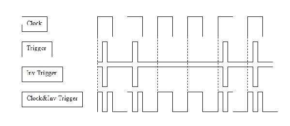
normally the gates are on until the next step is active, thus you have always a "merge" of succsessive gates.
i once thought of pimping my baby10 by adding AND gates (but i did not implement this due to all the other ideas/projects - it's still on my do-to-list). they would AND the incoming clock signal and the gates from the 4017. this would provide triggers with the same lenght as the incoming clock signal.
then we would just need a clock with pulsewidth modulation 
BTW for the manual switch on my chematic: it does not work very well. refer to my sequential switch schematic. the debouncing for the switch works like a charm. you might want to add a diode as well.
_________________

cheers,
matthias
____________
Big Boss at fonitronik
Tech Buddy at Random*Source |
|
|
Back to top
|
|
|
ashaxx
Joined: Jun 15, 2009
Posts: 7
Location: uk
|
| Posted: Thu Aug 27, 2009 7:40 am Post subject:
baby ten sequencer |
|
|
| ive been thinking of building a baby ten sequencer saw some pretty cool videos on youtube, it looks easy enough to build but i§m not exactly sure what the sequencer is trggering, what do the pulse outs go into?i§m thinking about just sequencing like an 40106 oscillator or somehting, is this what it could be used for if so how?where would i put the pulse outs from the sequencer into the oscillator, thanks |
|
|
Back to top
|
|
|
fonik
Joined: Jun 07, 2006
Posts: 3950
Location: Germany
Audio files: 23
|
| Posted: Thu Aug 27, 2009 8:49 am Post subject:
Re: baby ten sequencer |
|
|
| ashaxx wrote: | | ive been thinking of building a baby ten sequencer saw some pretty cool videos on youtube, it looks easy enough to build but i§m not exactly sure what the sequencer is trggering, what do the pulse outs go into?i§m thinking about just sequencing like an 40106 oscillator or somehting, is this what it could be used for if so how?where would i put the pulse outs from the sequencer into the oscillator, thanks |
the baby10 in my configuration puts out CVs (control voltages set by potentiometers) and Gates (logic voltages; HI or LOW).
with the CVs you could control i.e. the frequrncy of the oscillator or a filter, or...
with the gates you could control i.e. an envelope generator that controls a VCA or VCF or whatever, or other sequencers, or...
_________________
cheers,
matthias
____________
Big Boss at fonitronik
Tech Buddy at Random*Source |
|
|
Back to top
|
|
|
ashaxx
Joined: Jun 15, 2009
Posts: 7
Location: uk
|
| Posted: Thu Aug 27, 2009 10:34 am Post subject:
baby ten |
|
|
| so for example could i use the cv output going into a 40106 oscillator and the pulse outs would go to something that needs triggers |
|
|
Back to top
|
|
|
fonik
Joined: Jun 07, 2006
Posts: 3950
Location: Germany
Audio files: 23
|
| Posted: Thu Aug 27, 2009 11:58 am Post subject:
|
|
|
correct.
keep in mind that in this simple configuration of the 4017 based sequencer two subsequent gates would merge to one long gate.
_________________
cheers,
matthias
____________
Big Boss at fonitronik
Tech Buddy at Random*Source |
|
|
Back to top
|
|
|
ashaxx
Joined: Jun 15, 2009
Posts: 7
Location: uk
|
| Posted: Thu Aug 27, 2009 2:57 pm Post subject:
baby ten |
|
|
| ok so i can use the cv with amn oscillator but where on the oscillator would i put the cv out from the sequencer?say i 40106 oscillator? |
|
|
Back to top
|
|
|
fonik
Joined: Jun 07, 2006
Posts: 3950
Location: Germany
Audio files: 23
|
| Posted: Thu Aug 27, 2009 10:23 pm Post subject:
Re: baby ten |
|
|
| ashaxx wrote: | | ok so i can use the cv with an oscillator but where on the oscillator would i put the cv out from the sequencer?say i 40106 oscillator? |
you would need a VCO, Voltage Controlled Oscillator, providing a CV input; i.e. this one from synthmonger: http://electro-music.com/forum/topic-28799.html
_________________
cheers,
matthias
____________
Big Boss at fonitronik
Tech Buddy at Random*Source |
|
|
Back to top
|
|
|
ashaxx
Joined: Jun 15, 2009
Posts: 7
Location: uk
|
| Posted: Sun Aug 30, 2009 2:37 pm Post subject:
baby ten |
|
|
| cool thanks a lot, im still pretty new to this, is the ramp out an audio out? |
|
|
Back to top
|
|
|
EdisonRex
Site Admin

Joined: Mar 07, 2007
Posts: 4579
Location: London, UK
Audio files: 172
|
| Posted: Mon Aug 31, 2009 6:04 am Post subject:
Re: baby ten |
|
|
| ashaxx wrote: | | cool thanks a lot, im still pretty new to this, is the ramp out an audio out? |
Yes, that will be a fairly strong audio signal. Your mixer should expect line level and it'll be loud. You'll probably want a filter at some point and envelope generators, but one thing at a time 
_________________
Garret: It's so retro.
EGM: What does retro mean to you?
Parker: Like, old and outdated.
Home,My Studio,and another view |
|
|
Back to top
|
|
|
Lie3vie3

Joined: Aug 31, 2009
Posts: 3
Location: Belgium
|
| Posted: Wed Sep 02, 2009 6:29 am Post subject:
|
|
|
| Quote: | | info: this guy added skip function to his version,very nice! |
Well, I'm this guy.  I didn't really added the function but I achieved it with some extra patching. (although you can integrate a skip function with an AND Gate and an inverter, more on this later) I didn't really added the function but I achieved it with some extra patching. (although you can integrate a skip function with an AND Gate and an inverter, more on this later)
Due to some troubles with my account I had to make a new one and reupload the video.
http://www.youtube.com/watch?v=6yBx8KXtxVY
| Quote: | | the 4017 needs a clock signal of at least 1/2 supply voltage. so if you power the 4017 from i.e. 15V the threshold is at approx. 7.5V |
I don't think this is true. At least in my case 3V was the threshold (my Baby10 operates on 12V so the 3V is 1/3 Vdd)
| Quote: |
edit: i would try to avoid too high a voltage though - as i understand from reading this forum, cmos ics can be destroyed by that? so maybe measure the trigger voltage first? (somebody please correct me if i am wrong)
|
Indeed, a to high voltage will kill your IC. Normally the maximum input voltage of a CMOS IC is Vdd + 0.5V. Also always make sure if you work with unipolar power supplies to protect your circuit from negative voltages. This can easily be done with some diodes.
| Quote: | normally the gates are on until the next step is active, thus you have always a "merge" of succsessive gates.
i once thought of pimping my baby10 by adding AND gates (but i did not implement this due to all the other ideas/projects - it's still on my do-to-list). they would AND the incoming clock signal and the gates from the 4017. this would provide triggers with the same lenght as the incoming clock signal.
then we would just need a clock with pulsewidth modulation Very Happy
|
Fonik, I have built your version of the Baby10 and made some adaptations including this one. Unfortunately this wasn't as simple as you described it. You will have to take the propagation delay of the 4017 into account. If you don't do, the gate signal will occur later then the clock signal and will, due to lasting too long, also send out a trigger signal on the next step. To counter this you can chain some AND gates to add some delay to the clock signal.
(I hope I described this clearly enough, English isn't my first language ...)
I made some explaining schematics (for the skip function and the separate triggers mod) and posted them on synthforum.nl. You can find them here
The explanation is written in Dutch but if you have some questions you are free to ask them. |
|
|
Back to top
|
|
|
fonik
Joined: Jun 07, 2006
Posts: 3950
Location: Germany
Audio files: 23
|
| Posted: Wed Sep 02, 2009 6:56 am Post subject:
|
|
|
| Lie3vie3 wrote: | | Quote: | | the 4017 needs a clock signal of at least 1/2 supply voltage. so if you power the 4017 from i.e. 15V the threshold is at approx. 7.5V |
I don't think this is true. At least in my case 3V was the threshold (my Baby10 operates on 12V so the 3V is 1/3 Vdd) |
good to know. i thought i read it in a datasheet, but maybe it is just by hearsay.
| Quote: | Fonik, I have built your version of the Baby10 and made some adaptations including this one. Unfortunately this wasn't as simple as you described it. You will have to take the propagation delay of the 4017 into account. If you don't do, the gate signal will occur later then the clock signal and will, due to lasting too long, also send out a trigger signal on the next step. To counter this you can chain some AND gates to add some delay to the clock signal.
(I hope I described this clearly enough, English isn't my first language ...) |
okay, i see. that makes sense. thank for pointing that out, and thank you for sharing.
i will consider your findings and richards ideas from this thread:
http://electro-music.com/forum/topic-25228.html&postorder=asc&highlight=4017+trigger&start=25
_________________
cheers,
matthias
____________
Big Boss at fonitronik
Tech Buddy at Random*Source |
|
|
Back to top
|
|
|
fonik
Joined: Jun 07, 2006
Posts: 3950
Location: Germany
Audio files: 23
|
| Posted: Fri Sep 04, 2009 12:36 am Post subject:
|
|
|
i thought a bit about the 'skip function' and could not come to a solution. how could one skip a step in a 4017?
_________________
cheers,
matthias
____________
Big Boss at fonitronik
Tech Buddy at Random*Source |
|
|
Back to top
|
|
|
TekniK
Joined: Aug 10, 2008
Posts: 1059
|
| Posted: Fri Sep 04, 2009 2:26 am Post subject:
|
|
|
| fonik wrote: | | i thought a bit about the 'skip function' and could not come to a solution. how could one skip a step in a 4017? |
http://synthforum.nl/forums/showthread.php?p=1141314#post1141314
| Quote: | Separated Triggers
Een nadeel bij deze versie van de Baby 10 is dat er geen twee opeenvolgend trigger signalen kunnen gemaakt worden. Dit komt omdat je ,als je twee opeenvolgende gates activeert, je één lang gate signaal krijgt. Dit kan opgelost worden door een 4081 And Gate toe te voegen: door het clock signaal te "And-en" met de gate uitgang krijg je triggers die even lang zijn als het clock signaal. Het probleem is dat door de propagation delay van de 4017 het gate signaal iets later zal zijn dan het clock signaal. Door die verschuiving van het gate signaal zal bij de volgende stap ook een trigger gegeven worden, ook als dit niet de bedoeling is. Om dit op te lossen kan je de overblijvende En poorten van de 4081 gebruiken om het clock signaal gelijk te brengen met het gate signaal (wat niet gegarandeerd zal werken!). Dus het is aangeraden om dit eerst eens uit testen op een breadboard. |
Translate:
An incovenience with this version of the baby10 is that u can not obtain 2 trigger signals after each one.This is because if u activates 2 gates after each one the result will be one long gate signal.This can be resolved by adding an 4081 AND gate:by 'AND-ing' the clock with the output u get triggers that are the same lenght as the clock signal.The problem is that because of the propagation delay from the 4017 the gate signal will become a bit later then the clock signal.Because of this gate signal shift u will get another trigger at the next step even this will not be desired.To resolve this u can use the remaining EN gates of the 4081 to allign the clock with the gate signal (but this u should test it first as its not guaranteed that this will work)
| Quote: | Skip Step
Om nu stappen te kunnen overslaan hoeft er niet veel meer toegevoegd worden. Je neemt de clock ingang en combineert die met het geïnverteerde trigger signaal. Dit stuur je dan naar de clock ingang van de Baby 10. Om dit te laten werken moet het clock signaal wel langer zijn dan het trigger signaal. Door de propagation delay worden zo twee clock pulsjes gegenereerd en worden er twee stappen tegelijk vooruit gegaan. |
Translate:
To skip steps now,not much have to be added.You take the clock input and combine this with the inverted trigger signal.then u send this to the clock input of the baby10.To have this properly working the clock signal have to be larger as the trigger signal.Because of the propagation delay there are 2 clock pulses that been generated and so the are 2 steps skipping at the same time. |
|
|
Back to top
|
|
|
fonik
Joined: Jun 07, 2006
Posts: 3950
Location: Germany
Audio files: 23
|
| Posted: Fri Sep 04, 2009 3:08 am Post subject:
|
|
|
| Quote: | | To skip steps now,not much have to be added.You take the clock input and combine this with the inverted trigger signal.then u send this to the clock input of the baby10.To have this properly working the clock signal have to be larger as the trigger signal.Because of the propagation delay there are 2 clock pulses that been generated and so the are 2 steps skipping at the same time. |
so if i combine the clock with the inverted trigger signal i get a clock signal and an additional subsequent short trigger with a small delay, right? then i would actualy not skip a step (overleap), but have still two subsequent steps, with a very short delay time? and as long as the inverted trigger (created from gate2trigger conversion and inverter) is within the duty cycle of the original clock signal this would be no problem, as long as i AND-gate the 4017 output with the original clock.
or didn't i get it yet?
_________________
cheers,
matthias
____________
Big Boss at fonitronik
Tech Buddy at Random*Source |
|
|
Back to top
|
|
|
TekniK
Joined: Aug 10, 2008
Posts: 1059
|
| Posted: Fri Sep 04, 2009 3:46 am Post subject:
|
|
|
| fonik wrote: |
or didn't i get it yet? |
i just did the translate,L3V3 will need to clarifie any details imo
 |
|
|
Back to top
|
|
|
DGTom

Joined: Dec 08, 2008
Posts: 211
Location: Adelaide
Audio files: 3
G2 patch files: 1
|
| Posted: Fri Sep 04, 2009 9:10 am Post subject:
|
|
|
| the way I read it, you skip a beat, not a step, there are just 2 steps in the space of one? kinda cool. |
|
|
Back to top
|
|
|
Lie3vie3
Joined: Aug 31, 2009
Posts: 3
Location: Belgium
|
|
|
Back to top
|
|
|
sneakthief

Joined: Jul 24, 2006
Posts: 569
Location: Berlin
|
| Posted: Wed Oct 28, 2009 12:19 am Post subject:
|
|
|
somewhat related question:
a friend of mine asked how you would chain a couple of these together to make a 20-step sequencer. i imagine you'd use a logic gate tied to the inhibit inputs and the last step, right?
i've been hunting around and can't find other discussions about this that i stumbled across in the past.
_________________
Sneak-Thief - raw electrofunk |
|
|
Back to top
|
|
|
fonik
Joined: Jun 07, 2006
Posts: 3950
Location: Germany
Audio files: 23
|
|
|
Back to top
|
|
|
blue hell
Site Admin

Joined: Apr 03, 2004
Posts: 24673
Location: The Netherlands, Enschede
Audio files: 330
G2 patch files: 320
|
| Posted: Wed Oct 28, 2009 5:45 am Post subject:
|
|
|
| fonik wrote: | below is a schematic for at least 18 steps.
i don't know from where i got this schematic, so if someone knows the source i would replace the attachement by a link... |
Found it : http://www.bowdenshobbycircuits.info/page5.htm#4017-7.gif - it was the first Bill Bowden Google came up with 
_________________
Jan
also .. could someone please turn down the thermostat a bit.

9 3 4 .. erm .. not 13 then? .. hmm, ah eight! .. yeah yeah as in 8647 .. 47 is an 88 .. pwew .. numbles! |
|
|
Back to top
|
|
|
sneakthief
Joined: Jul 24, 2006
Posts: 569
Location: Berlin
|
| Posted: Wed Oct 28, 2009 6:08 am Post subject:
|
|
|
thanks!
does anyone know of a schematic that can cascade 2 decade counters and have a total of 20 steps and not 18?
_________________
Sneak-Thief - raw electrofunk |
|
|
Back to top
|
|
|
DGTom
Joined: Dec 08, 2008
Posts: 211
Location: Adelaide
Audio files: 3
G2 patch files: 1
|
|
|
Back to top
|
|
|
|

 Forum index » DIY Hardware and Software