| Author |
Message |
jean-louise

Joined: Apr 27, 2009
Posts: 73
Location: berlin
Audio files: 2
|
 Posted: Wed Aug 26, 2009 9:30 am Post subject: Posted: Wed Aug 26, 2009 9:30 am Post subject:
|
  |
|
replying to myself once again 
i now chose a 33uF capacitor as the output cap.
it's just what i had lying around and it left enough bass (i couldn't hear a difference to the DC coupled VCA).
the VCA does not work perfectly as it sometimes adds a sort of faint reverb or release even if the release is turned off. maybe a bug in my soldering or something.
*but* it works well enough for me until i build a more advanced VCA or debug my very messy stripboard of the René Schmitz VCA-2 that sounded smoother but was not loud enough and had a lot of VCO bleedthrough.
i still have to learn how to not turn slightly more complex circuits into a complete mess. 

jan |
|
|
Back to top
|
|
 |
blue hell
Site Admin

Joined: Apr 03, 2004
Posts: 24672
Location: The Netherlands, Enschede
Audio files: 330
G2 patch files: 320
|
| Posted: Wed Aug 26, 2009 9:41 am Post subject:
|
|
|
Well ... its good you got it working anyway 
I tried to calculate the decoupling cap that would be needed ... but found it hard to come up with a good gues for how it would behave with large input signals ... the frequency response would depend upon the signal level very much ... one of the problems of using simple circuits like this one ... trial and error is actually a good way here.
_________________
Jan
also .. could someone please turn down the thermostat a bit.

9 3 4 .. erm .. not 13 then? .. hmm, ah eight! .. yeah yeah as in 8647 .. 47 is an 88 .. pwew .. numbles! |
|
|
Back to top
|
|
|
richardc64

Joined: Jun 01, 2006
Posts: 679
Location: NYC
Audio files: 26
|
| Posted: Wed Aug 26, 2009 11:32 am Post subject:
|
|
|
Sorry, I was occupied.
33uF seems a bit much. Probably 10, 4.7 or even 1uF would be enough.
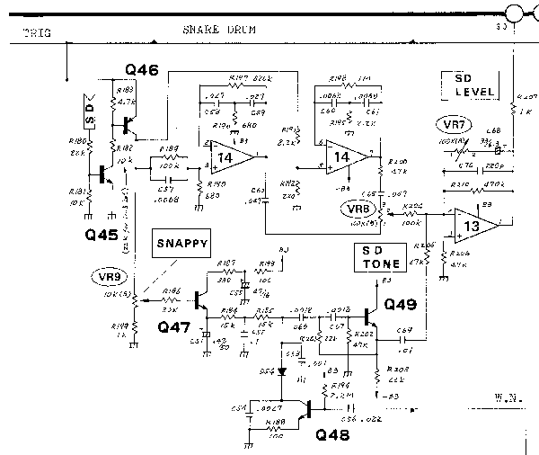
The 1-transistor VCA is from a percussion unit and used for the shaping of noise for cymbals, snare, etc. The coupling caps were therefore small -- .001uF and less, depending, as you've discovered by trial-error, jean, on the frequency range of the input and that of the desired output.
_________________
Revenge is a dish best served with a fork... to the eye |
|
|
Back to top
|
|
|
jean-louise
Joined: Apr 27, 2009
Posts: 73
Location: berlin
Audio files: 2
|
| Posted: Wed Aug 26, 2009 6:18 pm Post subject:
|
|
|
| Blue Hell wrote: | | found it hard to come up with a good gues for how it would behave with large input signals ... the frequency response would depend upon the signal level very much |
still for example the input attenuation changes quite alot of the character of the sound. the whole thing is not really predictable.
-but that is also fun - i think i'll keep this VCA even when i have a more advanced one - it's so small and dirty-sounding 
| richardc64 wrote: | | 33uF seems a bit much. Probably 10, 4.7 or even 1uF would be enough. |
i couldn't find those $!§"?#*%&## - 4.7 capacitors! 
.. would it be better to put in a smaller capacitor?
jean |
|
|
Back to top
|
|
|
synthmonger
Joined: Nov 16, 2006
Posts: 578
Location: flada
Audio files: 3
|
| Posted: Tue Sep 29, 2009 6:30 pm Post subject:
|
|
|
| jean-louise wrote: | | Blue Hell wrote: | | found it hard to come up with a good gues for how it would behave with large input signals ... the frequency response would depend upon the signal level very much |
still for example the input attenuation changes quite alot of the character of the sound. the whole thing is not really predictable.
-but that is also fun - i think i'll keep this VCA even when i have a more advanced one - it's so small and dirty-sounding
| richardc64 wrote: | | 33uF seems a bit much. Probably 10, 4.7 or even 1uF would be enough. |
i couldn't find those $!§"?#*%&## - 4.7 capacitors!
.. would it be better to put in a smaller capacitor?
jean |
You'll cut higher frequencies with a big cap. Richard's suggestion of 1-10uF works well. I like to use 1uF for the MS-20 VCA. It is pretty dang noisy though ;x
_________________
Youtube!
modular demos!
Whacky tunes! |
|
|
Back to top
|
|
|
MickeyDelp

Joined: Feb 26, 2010
Posts: 42
Location: Austin TX
Audio files: 1
|
|
|
Back to top
|
|
|
Cynosure
Site Admin

Joined: Dec 11, 2010
Posts: 1029
Location: Toronto, Ontario - Canada
Audio files: 82
|
| Posted: Fri Dec 31, 2010 12:39 pm Post subject:
|
|
|
I have tried the 2 circuits outlined here, and all I get on the output is the envelope. There is no note with it.
I am generating the note with a 40106, which is then divided with a 4040. If I test the output of the 40106, the signal seems fine. However, coming out of the 4040 the signal is very low. The signal out of the 4040 was fine before I added these two circuits.
If I try bypassing the 4040, then there is no signal generated at all by the 40106.
I tried adding a diode to link the note out of the 4040 to the rest of the circuit, but it was as though no signal passed through the diode.
Any idea why the envelope isn't effecting the note? Any idea why the signal level out of the 4040 is extremely low? Is it a matter of testing capacitor values like previously mentioned? |
|
|
Back to top
|
|
|
Cynosure
Site Admin
Joined: Dec 11, 2010
Posts: 1029
Location: Toronto, Ontario - Canada
Audio files: 82
|
| Posted: Fri Dec 31, 2010 1:07 pm Post subject:
|
|
|
Update - IF I use extremely low capacitor values then it works when I bypass the switch for the note.
I can see this still being useful in a mono synth, but is it possible to use it on a poly? Would I need one of the circuits for every note? |
|
|
Back to top
|
|
|
JovianPyx

Joined: Nov 20, 2007
Posts: 1988
Location: West Red Spot, Jupiter
Audio files: 224
|
| Posted: Tue Jan 04, 2011 8:40 am Post subject:
|
|
|
In the analog world, think of a poly synth as essentially a set of N identical mono synths for N voices all controlled by a single common keyboard or MIDI controller.
So yes, any circuit needed by any "voice" (voice equates to a single mono synth which comprises a poly) will need to be multiplied by the total number of voices you need/want.
_________________
FPGA, dsPIC and Fatman Synth Stuff
Time flies like a banana.
Fruit flies when you're having fun.
BTW, Do these genes make my ass look fat?
corruptio optimi pessima
|
|
|
Back to top
|
|
|
Cynosure
Site Admin
Joined: Dec 11, 2010
Posts: 1029
Location: Toronto, Ontario - Canada
Audio files: 82
|
| Posted: Tue Jan 04, 2011 8:20 pm Post subject:
|
|
|
That makes sense, but most synths only have a single set of envelope controls. How do you modify attack or release for several sets of mono voices with a single pot?
I have decided against using this envelope for my current project because the note from the oscillator has to continue to play even after the key switch is turned off in order to acheive the release effect. I have another project planned that this will work well with. |
|
|
Back to top
|
|
|
JovianPyx
Joined: Nov 20, 2007
Posts: 1988
Location: West Red Spot, Jupiter
Audio files: 224
|
| Posted: Tue Jan 04, 2011 8:51 pm Post subject:
|
|
|
The pot generates a control voltage that is fed to each of the voices.
_________________
FPGA, dsPIC and Fatman Synth Stuff
Time flies like a banana.
Fruit flies when you're having fun.
BTW, Do these genes make my ass look fat?
corruptio optimi pessima
|
|
|
Back to top
|
|
|
Cynosure
Site Admin
Joined: Dec 11, 2010
Posts: 1029
Location: Toronto, Ontario - Canada
Audio files: 82
|
| Posted: Tue Jan 04, 2011 8:59 pm Post subject:
|
|
|
| OH! Now that makes sense. I have been trying to control the sound signal after it's generated instead of controlling the signal going into the oscillator. |
|
|
Back to top
|
|
|
Ojd
Joined: Feb 22, 2008
Posts: 66
Location: Ua
Audio files: 1
|
| Posted: Thu Jan 27, 2011 5:48 am Post subject:
|
|
|
So if I understand this image correct, the - (negative) side of signal gets cut? Same for LFO's feeding circuit (where envelope in this pic)? This way feeding LFO gets almost useless.
 |
|
|
Back to top
|
|
|
JovianPyx
Joined: Nov 20, 2007
Posts: 1988
Location: West Red Spot, Jupiter
Audio files: 224
|
| Posted: Thu Jan 27, 2011 6:33 am Post subject:
|
|
|
Yes, the negative half cuts cut off because the negative half cycles cause the transistor base-emitter junction to be reverse biased and thus it won't conduct.
As for where the envelope is, the waveforms here appear hand drawn, so they are not precise, but assume that the input is a constant amplitude sine wave. Looking at the bottom of the output wave, the negative cycles should be fairly squarely cut off, that is, there won't be rounding (or much anyway) of the waveform. The bottom should look like someone cut it with a scissors. The envelope looks like it decays exponentially, but again, hand drawn. The output's waveform peaks should just touch the expo envlope waveform. In this case, the envelope is shaping only the top of the waveform and it will be most apparent by looking at the peaks.
HTH
_________________
FPGA, dsPIC and Fatman Synth Stuff
Time flies like a banana.
Fruit flies when you're having fun.
BTW, Do these genes make my ass look fat?
corruptio optimi pessima
|
|
|
Back to top
|
|
|
Ojd
Joined: Feb 22, 2008
Posts: 66
Location: Ua
Audio files: 1
|
|
|
Back to top
|
|
|
-minus-
Joined: Oct 26, 2008
Posts: 787
Audio files: 13
|
| Posted: Thu Feb 10, 2011 2:01 pm Post subject:
|
|
|
I've had some success with a single transistor VCA too. I've based mine from the MFOS wp20 schematics.
CV INPUT goes through two 330K R's in series into the base of a 2N3904 transistor. The join between the two resistors has a 0.1uF cap going to ground. Also a 1M R going from base to ground.
Audio input goes through a 0.1uF cap then through a 1K R to collector. Collector also has 4.7K R going to ground...
Emitter has a 47K R going to ground. Output from the emitter through a +/- 10uF cap.
I've left off the op amp and I'm just taking the signal out from the 10uF cap. I'm sure there are nicer ways to do this, but for the low parts count and simplicity of this circuit, I'm quite impressed. I'm feeding the CV with a LFO triangle. The audio signal in is two triangle audio oscillators mixed with 1K resistors. They fade in and out well! |
|
|
Back to top
|
|
|
JovianPyx
Joined: Nov 20, 2007
Posts: 1988
Location: West Red Spot, Jupiter
Audio files: 224
|
| Posted: Thu Feb 10, 2011 2:43 pm Post subject:
|
|
|
A LFO with a shape like triangle is a situation where this kind of VCA will work fairly well.
The reason that this and similar circuits are not popular among modular synth users is that it will have significant CV bleed through which manifests as a noticable thump or pop for envelopes that have a transient (like an ADSR does).
The distortion caused by rectification chopping off all of the negative half cycles will be ever present and will color the timbre of the sound. That is, if you put a sinewave into it, you will not get a sinewave out, harmonics will be added by the distortion. (may or may not be a bad thing since this amounts to a form of waveshaping)
The CV bleed through problem is why most modular builders use more complex circuits for VCA. However, if the bleed through thump/pop when used with an envelope generator enhances your sound, then it is a good thing.
_________________
FPGA, dsPIC and Fatman Synth Stuff
Time flies like a banana.
Fruit flies when you're having fun.
BTW, Do these genes make my ass look fat?
corruptio optimi pessima
|
|
|
Back to top
|
|
|
-minus-
Joined: Oct 26, 2008
Posts: 787
Audio files: 13
|
| Posted: Thu Feb 10, 2011 4:04 pm Post subject:
|
|
|
Ah ok. I guess for what I am doing and the level of competency I am at right now this will do. I'm mainly playing around with oscillators making drones.
I'm just wondering if you have any suggestions as to what I should perhaps be looking at for a VCA when I evolve to building more serious gear. Any suggestions? |
|
|
Back to top
|
|
|
JovianPyx
Joined: Nov 20, 2007
Posts: 1988
Location: West Red Spot, Jupiter
Audio files: 224
|
| Posted: Thu Feb 10, 2011 5:08 pm Post subject:
|
|
|
Probably the most common VCAs use an OTA (Operational Transconductance Amplifier - quite a mouthful of words) which is an amplifier that has current controlled gain.
LM13700 is one such part (it's a dual OTA). In many respects it works like an opamp, but the amount of gain can be controlled by current. The audio input goes into the input terminal and the control current goes into a pin called Iabc (abc stands for Amplifier Bias Current).
So the envelope or other modulating signal would be first converted from voltage to current and then applied to the Iabc pin. OTAs work without chopping off the negative half cycles and operate as true AC amplifiers. This fact greatly reduces the "thump" I wrote of because the envelope is impressed onto both the negative and positive cycles of the input signal. This means the positive envelope effect cancels the negative envelope effect with respect to CV bleed through whereas the lack of the negative side for the single transistor VCA cannot do this cancellation which allows the thump to appear on the audio output signal. Some trimming of OTA input offset is usually required to get rid of any residual thump still heard, but even at it's worst it will work far better than a single transistor VCA.
To learn more about OTAs, you can download a PDF copy of a datasheet (such as for LM13700). The one I have has numerous example circuits that help in understanding what they do and how to hook them up.
_________________
FPGA, dsPIC and Fatman Synth Stuff
Time flies like a banana.
Fruit flies when you're having fun.
BTW, Do these genes make my ass look fat?
corruptio optimi pessima
|
|
|
Back to top
|
|
|
-minus-
Joined: Oct 26, 2008
Posts: 787
Audio files: 13
|
| Posted: Thu Feb 10, 2011 6:59 pm Post subject:
|
|
|
| I noticed earlier that Ray uses the LM13700 on his MFOS VCA's among other things. I also noticed the trimpots too. I had no idea as to the workings of this IC, so thanks! I'll check out the datasheet. Obviously very useful devices. |
|
|
Back to top
|
|
|
richardc64
Joined: Jun 01, 2006
Posts: 679
Location: NYC
Audio files: 26
|
| Posted: Fri Feb 11, 2011 12:32 am Post subject:
|
|
|
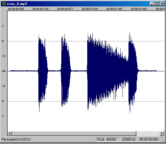
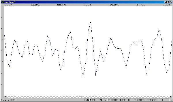
The bottom doesn't get cut off. The input signal gets shifted up by R1. The only way the bottom -- or top, for that matter -- could get chopped off is by overdriving the transistor with too large a signal; more than 2-3vpp or so. True, the output isn't symmetrical about it's center, where ever that may be, but that can be partly corrected by a capacitor at the output.
I don't have a 'scope, but I captured images in Wavosaur of one of my samples that used this VCA. I don't see any flattening of the bottom, even after zooming in I-don't-know-how-many times. It's not a sine wave because the input wasn't a sine: it was 4 schmitt oscillators and white noise mixed in an attempt to create a hi-hat.
| Description: |
|
| Filesize: |
50.29 KB |
| Viewed: |
52137 Time(s) |
|
| Description: |
|
| Filesize: |
91.35 KB |
| Viewed: |
1746 Time(s) |
| This image has been reduced to fit the page. Click on it to enlarge. |
|
| Description: |
|

Download (listen) |
| Filename: |
ccoc_6.mp3 |
| Filesize: |
40.5 KB |
| Downloaded: |
2671 Time(s) |
_________________
Revenge is a dish best served with a fork... to the eye |
|
|
Back to top
|
|
|
JovianPyx
Joined: Nov 20, 2007
Posts: 1988
Location: West Red Spot, Jupiter
Audio files: 224
|
| Posted: Fri Feb 11, 2011 2:09 am Post subject:
|
|
|
Ah, I see - R1 supplies a bias which would prevent the rectification, but not the thump because the assymetry with respect to zero volts is still there. The assymetry should cause the thump. I really wish the waveform had not been hand drawn.
Is there no thump?
_________________
FPGA, dsPIC and Fatman Synth Stuff
Time flies like a banana.
Fruit flies when you're having fun.
BTW, Do these genes make my ass look fat?
corruptio optimi pessima
|
|
|
Back to top
|
|
|
Dan Lavin

Joined: Nov 09, 2006
Posts: 649
Location: Spring Lake, Mi, USA
Audio files: 21
|
| Posted: Fri Feb 11, 2011 6:56 am Post subject:
|
|
|
Scott,
I've spent time with the DR110 and this circuit and there is no thumping. At least hard thumping, that is. It's possible there could be a little clicking as these are percussion voices and a little click wouldn't be a bad thing in a percussion voice.
_________________
Synth DIY since 1977! |
|
|
Back to top
|
|
|
JovianPyx
Joined: Nov 20, 2007
Posts: 1988
Location: West Red Spot, Jupiter
Audio files: 224
|
| Posted: Fri Feb 11, 2011 7:14 am Post subject:
|
|
|
Right, and that's what I said - it might be good for what a given user does. And if it is good, then you have a lovely inexpensive circuit.
However, the click/pop/thump is there as I stated. The timbre nature of it will vary with the shape of the modulation envelope. fast attack and decay will give a click or pop where slower attack/decay would give a more bassy thump (which as I said may or may not be useful to a given user).
If you want to hear just how much thump/click is there, listen using the VCA with an ADSR (fast attack) and with _no_ audio input at all. You will hear it whenever the ADSR is triggered. A properly trimmed OTA-based VCA will do this too - but to a far lesser degree. Proper OTA offset trimming can reduce it to inaudible. It can be a matter of philosophy, some would argue that it's better to start with VCA the doesn't have a thump/pop/click and _add_ it if it's desired. Adding the thump is a matter of mixing some of the ADSR output into the audio. If you use a VCA that has the thump/pop/click and don't want it, then what?
I think that the nature of the audio content will make a difference how audible the thump/click/pop is. Noise will probably mask it, whereas using a sinewave as input (to get a flutey sound) will have prominent thump/click/pop sounds.
Please understand - I am NOT trying to discourage the use of this circuit. I'm merely pointing out that it has flaws which will affect your sound. If the effect is something you like - then use it. If not, then I've offered an alternative.
_________________
FPGA, dsPIC and Fatman Synth Stuff
Time flies like a banana.
Fruit flies when you're having fun.
BTW, Do these genes make my ass look fat?
corruptio optimi pessima
|
|
|
Back to top
|
|
|
MickeyDelp
Joined: Feb 26, 2010
Posts: 42
Location: Austin TX
Audio files: 1
|
| Posted: Fri Feb 11, 2011 7:28 am Post subject:
|
|
|
JovianPyx,
You're right-on with your comments. This circuit is perfect for percussion sounds, as it was used in the TR-808. And it is acceptable for other lo-fi usage. If you need a more subtle VCA, then use a different circuit. The right tool for the right job.
_________________
MickeyDelp.com
Delptronics.com |
|
|
Back to top
|
|
|
|

 Forum index » DIY Hardware and Software