| Author |
Message |
JingleJoe

Joined: Nov 10, 2011
Posts: 878
Location: Lancashire, England
Audio files: 14
|
 Posted: Wed Dec 14, 2011 3:21 pm Post subject:
Why does this filter have two capacitors? And other queries. Posted: Wed Dec 14, 2011 3:21 pm Post subject:
Why does this filter have two capacitors? And other queries.
Subject description: Simple questions like this are never as simple as they seem |
  |
|
I've been researching alot of voltage controlled filters, trying to find the simplest and easiest to make and the designs in this thread keep cropping up.
But why does it have two capacitors in the feedback path? (My suspicion is that it is something to do with resonance or it increase the filter order) And what is the purpose of the 500pf cap in the middle of the feedback resistor in tim escobedo's one? And why does he say it's a "fake" low pass filter? This is a real low pass filter, I can see that it is! |
|
|
Back to top
|
|
 |
Mongo1
Joined: Aug 11, 2011
Posts: 411
Location: Raleigh NC
|
| Posted: Thu Dec 15, 2011 8:21 am Post subject:
|
|
|
I'm sure there are better answers out there (it's not clear to me how that filter actually works), but one thing is that the caps prevent the DC control voltage from getting pushed into either the input or output of the opamp.
Gary |
|
|
Back to top
|
|
|
richardc64

Joined: Jun 01, 2006
Posts: 679
Location: NYC
Audio files: 26
|
|
|
Back to top
|
|
|
JingleJoe
Joined: Nov 10, 2011
Posts: 878
Location: Lancashire, England
Audio files: 14
|
| Posted: Thu Dec 15, 2011 11:27 am Post subject:
|
|
|
Spiffing thankyou  Looks like I will have to look up twin T filters next Looks like I will have to look up twin T filters next 
Just thinking: if the diode is only acting as a crude voltage controlled resistor, could it be exchanged for a transistor/mosfet? or a vactrol? |
|
|
Back to top
|
|
|
umschmitt

Joined: Jun 29, 2011
Posts: 189
Location: brrlin
Audio files: 11
|
| Posted: Fri Dec 16, 2011 10:13 am Post subject:
|
|
|
Hey. Would someone be kind enough to elaborate or point towards further explanations about the exact role of this mysterious diode ? Thanks !
_________________
::U::N::S::C::H::N::E::L::L:: |
|
|
Back to top
|
|
|
richardc64
Joined: Jun 01, 2006
Posts: 679
Location: NYC
Audio files: 26
|
| Posted: Fri Dec 16, 2011 12:05 pm Post subject:
|
|
|
http://www.paia.com/ProdArticles/syndrum.htm
| Quote: | | This circuit has the embellishment of a simple Voltage Control mechanism. The diodes D1 and D2 are effectively in parallel with R4 (one of the components that determines pitch). As the CV-in voltage increases, the exponentially increasing current flow through these diodes causes their effective impedance to decrease, which raises the frequency of the twin-T network. |
The twin-T referred to is an oscillator, which is what this type of filter will do with high enough resonance (Q). But the principle is the same. And, yes, a transistor would do the job, too. Use an npn with emitter to ground, collector to where the 2 caps meet, and CV at the base.
_________________
Revenge is a dish best served with a fork... to the eye |
|
|
Back to top
|
|
|
JingleJoe
Joined: Nov 10, 2011
Posts: 878
Location: Lancashire, England
Audio files: 14
|
| Posted: Sat Dec 17, 2011 3:40 am Post subject:
|
|
|
| richardc64 wrote: | http://www.paia.com/ProdArticles/syndrum.htm
| Quote: | | This circuit has the embellishment of a simple Voltage Control mechanism. The diodes D1 and D2 are effectively in parallel with R4 (one of the components that determines pitch). As the CV-in voltage increases, the exponentially increasing current flow through these diodes causes their effective impedance to decrease, which raises the frequency of the twin-T network. |
The twin-T referred to is an oscillator, which is what this type of filter will do with high enough resonance (Q). But the principle is the same. And, yes, a transistor would do the job, too. Use an npn with emitter to ground, collector to where the 2 caps meet, and CV at the base. |
Fucking brilliant!
Pardon my french but thats just solved a huge mystery for me and made designing my filter much easier, thankyou! |
|
|
Back to top
|
|
|
umschmitt
Joined: Jun 29, 2011
Posts: 189
Location: brrlin
Audio files: 11
|
|
|
Back to top
|
|
|
umschmitt
Joined: Jun 29, 2011
Posts: 189
Location: brrlin
Audio files: 11
|
| Posted: Wed Dec 21, 2011 5:27 pm Post subject:
|
|
|
By the way, one more noobish question : I'm trying to adapt the values of this filter, mentioned at the top of this topic, to make it work at 5 volts. Yet my problem is how to add more frequency range ! Would someone have the magic "bridged T equation" with whom I could sort it out ? Or again point a direction towards some (hopefully not rocket) science ? Many thanks !
For the record, my actual settings are
resistor "across" op-amp : 220k
caps : 10nF
germanium diode
CV resistors : 10k
(hope I'm not drifting too much from the original topic)
_________________
::U::N::S::C::H::N::E::L::L:: |
|
|
Back to top
|
|
|
JingleJoe
Joined: Nov 10, 2011
Posts: 878
Location: Lancashire, England
Audio files: 14
|
| Posted: Wed Dec 21, 2011 5:59 pm Post subject:
|
|
|
You're not drifting too much at all, it's all relative  I want answers to any questions anyone has about these circuits too! I want answers to any questions anyone has about these circuits too! |
|
|
Back to top
|
|
|
umschmitt
Joined: Jun 29, 2011
Posts: 189
Location: brrlin
Audio files: 11
|
| Posted: Thu Dec 22, 2011 7:09 am Post subject:
|
|
|
That's cool. Aren't we still in the "let's see how these one amp twin/bridged T filters work" domain ?
Nevertheless. I think the main equation here is the famous Fc=1÷(2×pi×R×C) but my problem is to understand what hides behind the R in that case… This diode / voltage divider arrangement makes me confused about how to get a resistance value out of it. Here are some results of my experiments, several parameters to be tweaked, I'm a bit lost :
Increasing the value of the VC resistors lowers the frequency response of the filter, but I couldn't determine if it affects its overall range. This has to be the place where we can usefully vary things (or am I wrong), unfortunately I don't get the maths here… Otherwise modifying cap values changes the pitch, but I feel it can be used to 'tune' later the filter in a convenient range. And the 'across' resistor affects the filter's pitch and resonance, I think… (might need to be tuned also)
As one can see, I've reached my incompetence level ! Could somebody please help ?
_________________
::U::N::S::C::H::N::E::L::L:: |
|
|
Back to top
|
|
|
richardc64
Joined: Jun 01, 2006
Posts: 679
Location: NYC
Audio files: 26
|
| Posted: Thu Dec 22, 2011 8:59 am Post subject:
|
|
|
Yes, everything in "T" filters and oscillators interacts, and the presence of the diode -- which should be silicon, not germanium -- skews the equation.
My suggestion to get more range from the filter is to disconnect +V from the Cut Off pot so that only a resistance controls the initial CF and the CV input alone -- which can get its own pot -- acts on the diode.
Increase the CF pot to 250k or even 1Meg. If that makes the range too low you can decrease the caps.
_________________
Revenge is a dish best served with a fork... to the eye |
|
|
Back to top
|
|
|
umschmitt
Joined: Jun 29, 2011
Posts: 189
Location: brrlin
Audio files: 11
|
| Posted: Thu Dec 22, 2011 2:47 pm Post subject:
|
|
|
Thank you very much one more time, richardc64. Following your suggestion, we'd have something similar to this, but in an inverting fashion… I happen to be a bit familiar with this one, I hope it'll help.
So I stuck another pot (220k log, pins 1 & 2) to ground as you said and applied the math above, which gave me C's around 15 nF for a minimum Fc of 50 Hz. The good news is that it works. Plenty of sweep. The bad news is that I had to disconnect the remaining VC inputs to get that result. Then I reconnected them through a diode but they had little impact on the frequency. Then I tried different variations using a diode/op-amp rectifier to separate CVs from the pot to ground with no success. And now I scratch my head and wonder if it is even possible to use a resistor to ground and CVs side by side…
Ok things are getting further, but I still need to understand better what's going on and what's not. Any idea, people ?
| richardc64 wrote: | | the diode -- which should be silicon, not germanium |
Here, I just considered that all voltages had to be reduced accordingly, including the diode's voltage drop. That's my science of logical shortcuts. I must say I didn't notice much difference between the two.
_________________
::U::N::S::C::H::N::E::L::L:: |
|
|
Back to top
|
|
|
JingleJoe
Joined: Nov 10, 2011
Posts: 878
Location: Lancashire, England
Audio files: 14
|
| Posted: Fri Dec 23, 2011 4:56 am Post subject:
|
|
|
| So, what is that diode really doing? From the explanation above I thought it was acting as a voltage controlled resistor? But it seems like something more... |
|
|
Back to top
|
|
|
richardc64
Joined: Jun 01, 2006
Posts: 679
Location: NYC
Audio files: 26
|
|
|
Back to top
|
|
|
umschmitt
Joined: Jun 29, 2011
Posts: 189
Location: brrlin
Audio files: 11
|
| Posted: Fri Dec 23, 2011 8:58 am Post subject:
|
|
|
Well richardc64 answered while I was typing…
Thanks for the drawing, I'll give it a try. I appreciate that you take time to patiently explain things to people like me (ie understanding but slowly)…
Besides, I have no doubt that plenty of people already succeeded in having such a filter to work ! I'm not thinking I'm doing anything new, it's just that I'm trying to have a one amp VC filter working at 5 volts. If I stumble upon such a circuit, I'll use it as is with no problem !
Also please take note that I usually stay away from equations as much as possible !
_________________
::U::N::S::C::H::N::E::L::L:: |
|
|
Back to top
|
|
|
umschmitt
Joined: Jun 29, 2011
Posts: 189
Location: brrlin
Audio files: 11
|
| Posted: Sat Dec 24, 2011 11:12 am Post subject:
|
|
|
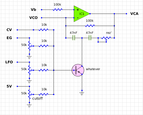
Oh I forgot to give a link to the circuit I'm working on, which uses the one op-amp filter discussed above. Here it is :
http://electro-music.com/forum/phpbb-files/mutant_ds_7_prelim_schem_525.png
Yeah now you understand better the catastrophe going on ! I suspect that one of the problems might be the presence of "voltage dividers" type attenuators, therefore we have resistances to ground in parallel with the diode or the pot as suggested by richardc64. I might also be completely wrong.
The way I found to overcome this is to use a transistor, as JingleJoe mentioned [edit : and richardc64 developed !] (thanks!) : Vc things through the base, collector to the T, emitter to ground, frequency pot to the T too. Yet not ideal, but works way better !
Yeehaa ! That's all for now, I'm out for a couple drinks ! Cheers !
_________________
::U::N::S::C::H::N::E::L::L::
Last edited by umschmitt on Sun Dec 25, 2011 4:39 pm; edited 1 time in total |
|
|
Back to top
|
|
|
JingleJoe
Joined: Nov 10, 2011
Posts: 878
Location: Lancashire, England
Audio files: 14
|
| Posted: Sat Dec 24, 2011 4:54 pm Post subject:
|
|
|
| umschmitt wrote: |
The way I found to overcome this is to use a transistor, as JingleJoe mentioned (thanks!) : Vc things through the base, collector to the T, emitter to ground, frequency pot to the T too. Yet not ideal, but works way better !
Yeehaa ! That's all for now, I'm out for a couple drinks ! Cheers ! |
just to clarify your arrangement could you post a circuit diagram please? I may have it right though: The transistor is conected as the diode is, but your CV goes to the base (through a 100k resistor?) and the initial/main frequency control pot is connected as normal? |
|
|
Back to top
|
|
|
umschmitt
Joined: Jun 29, 2011
Posts: 189
Location: brrlin
Audio files: 11
|
|
|
Back to top
|
|
|
JingleJoe
Joined: Nov 10, 2011
Posts: 878
Location: Lancashire, England
Audio files: 14
|
| Posted: Sun Dec 25, 2011 3:31 pm Post subject:
|
|
|
hah, whatever transistors, the newest brand of high fidelity medium power whatever-polar junction transevers! 
I would strongly advise 100k resistors on all things going into the caps and transistor, acctually the transistor may require lower resistance but I would put that main frequency pot through a 100k resistor just to be safe.
Thanks very much for the schematic, everything is becoming clear now  |
|
|
Back to top
|
|
|
umschmitt
Joined: Jun 29, 2011
Posts: 189
Location: brrlin
Audio files: 11
|
| Posted: Sun Dec 25, 2011 4:20 pm Post subject:
|
|
|
You're welcome, but why add those resistors everywhere ? I'm actually trying to have to be able to get the lowest possible resistance to ground at the T. For the whatever, I need to calculate how to achieve this (saturation ?) with CV pots maxed. Besides, I think - pardon the math - that the relation between cutoff R and frequency is the 1/n type, so we want those little R values… Except if I can find a 220 Gigaohm pot of course.
_________________
::U::N::S::C::H::N::E::L::L:: |
|
|
Back to top
|
|
|
umschmitt
Joined: Jun 29, 2011
Posts: 189
Location: brrlin
Audio files: 11
|
|
|
Back to top
|
|
|
JingleJoe
Joined: Nov 10, 2011
Posts: 878
Location: Lancashire, England
Audio files: 14
|
| Posted: Mon Dec 26, 2011 4:36 pm Post subject:
|
|
|
| Spiffing! Carry on the good work old sport, what did I say about those resistors eh? |
|
|
Back to top
|
|
|
JingleJoe
Joined: Nov 10, 2011
Posts: 878
Location: Lancashire, England
Audio files: 14
|
| Posted: Sat Feb 18, 2012 6:37 am Post subject:
|
|
|
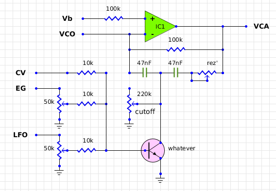
This circuit is so versatile 
I've been experimenting with it alot today, I really figured out alot of things ... but it's hard to word them right.
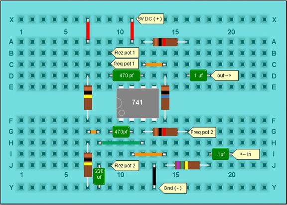
The transistor/capacitor combination filters the signal, yes, but it also allows much of the high frequency oscillations to be bypassed to ground, so they do not feed back into the op amp and are subsequently not attenuated, this gives you the resonance (see my thread on the resonator for a device which just adds resonance and no filtering). When the resonance potentiometer resistance is high, it is almost as though there is no connection between the capacitor on the output side and the output, so you end up with alot of unusual, frequency independant resonance, also changing other components will affect the resonance.
All components are changeable!
Both caps determine the resonance and filtering of the signal however the capacitor on the input side of the feedback path (the left hand side one in my diagram) has more to do with the resonance frequency and amount of resonance. I haven't played with it but I invite you to try some different values!
Attached is a diagram of the circuit I was using today. keep the input low, about 1 or 2 volts, for best results. If it gets too close to the op amp's limits it doesn't work very well. Also using a better op amp like an LM324 or something really special like a TLV072 would make this work alot better. I just happened to have an LM348 to hand (four 741's) so I used that.
Remamber, all components are changeable and thats what makes this circuit so good, but you may get better results with other values or other types of op amps or transistors.
I feel I should mention that I had some problems with slight irregularities on my input signal, I say problems, but that should be "features" Any distortion on your input signal can have a great effect, adding a power supply filter capacitor helped keep my input signal clean.
Last but not least;
Thankyou Umschmitt and richardc64
| Description: |
|
| Filesize: |
303.19 KB |
| Viewed: |
555 Time(s) |
| This image has been reduced to fit the page. Click on it to enlarge. |
![resonant filter [poor mans vcf].jpg](phpbb-files/thumbs/t_resonant_filter_poor_mans_vcf_176.jpg)
|
_________________
As a mad scientist I am ruled by the dictum of science: "I could be wrong about this but lets find out"
Green Dungeon Alchemist Laboratories |
|
|
Back to top
|
|
|
2kohm

Joined: Feb 19, 2013
Posts: 52
Location: germany
Audio files: 4
|
|
|
Back to top
|
|
|
|

 Forum index » DIY Hardware and Software