| Author |
Message |
Sebo

Joined: Apr 27, 2007
Posts: 564
Location: Argentina
|
 Posted: Fri Aug 22, 2008 11:24 am Post subject:
Craig Anderton Hip Bass Drum PCB Posted: Fri Aug 22, 2008 11:24 am Post subject:
Craig Anderton Hip Bass Drum PCB |
  |
|
Hi:
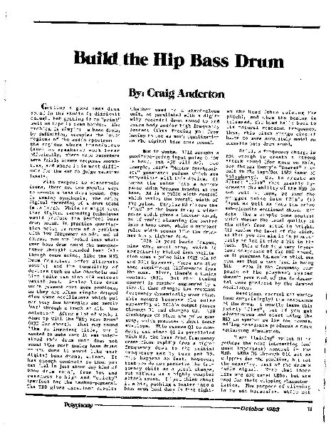
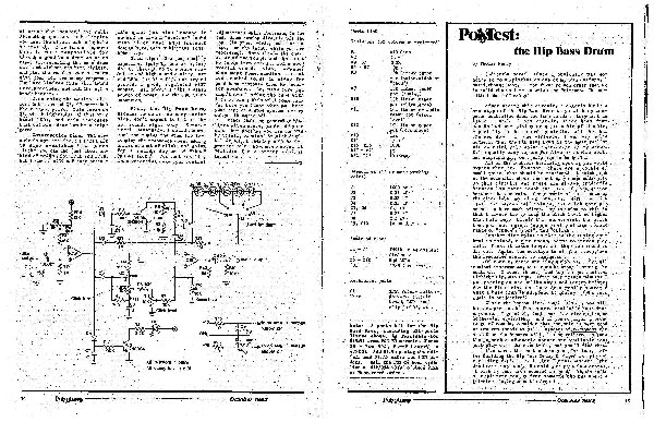
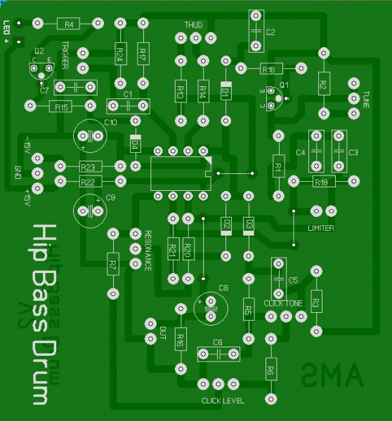
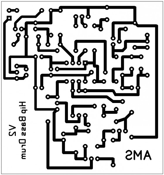
Here is my PCB design for the Craig Anderton Hip Bass Drum, I etched the
PCB some time ago, but never had the time to finish it, so is UNTESTED.
If someone get it to work, or find an error, please let me know.
The scan of the article was posted here at electro-music before, but I think
the files are lost, so I re-post it.
** edit: stinkebeest tested it and it worked for him **
| Description: |
|
| Filesize: |
604.93 KB |
| Viewed: |
3046 Time(s) |
| This image has been reduced to fit the page. Click on it to enlarge. |
|
| Description: |
|
| Filesize: |
1.21 MB |
| Viewed: |
5662 Time(s) |
| This image has been reduced to fit the page. Click on it to enlarge. |
|
| Description: |
|

Download (listen) |
| Filename: |
Hip Bass Drum PCB.bmp |
| Filesize: |
347.52 KB |
| Downloaded: |
3673 Time(s) |
| Description: |
|

Download (listen) |
| Filename: |
Hip Bass Drum Layout.bmp |
| Filesize: |
86.97 KB |
| Downloaded: |
3649 Time(s) |
| Description: |
|

Download (listen) |
| Filename: |
Hip Bass Drum Eagle.zip |
| Filesize: |
49.19 KB |
| Downloaded: |
2493 Time(s) |
_________________
Sebo
---------------------------------------
My Music:
https://www.facebook.com/cosaquitos/
Last edited by Sebo on Sun Jan 10, 2010 3:36 pm; edited 3 times in total |
|
|
Back to top
|
|
 |
widdly
Joined: Jun 25, 2007
Posts: 268
Location: singapore
G2 patch files: 2
|
 Posted: Tue Aug 26, 2008 2:50 am Post subject: Posted: Tue Aug 26, 2008 2:50 am Post subject:
|
  |
|
hey thanks. I've been looking for this article.
Last edited by widdly on Thu Aug 05, 2010 10:08 pm; edited 1 time in total |
|
|
Back to top
|
|
 |
Sebo

Joined: Apr 27, 2007
Posts: 564
Location: Argentina
|
 Posted: Wed Aug 27, 2008 9:31 am Post subject: Posted: Wed Aug 27, 2008 9:31 am Post subject:
|
  |
|
| widdly wrote: | | hey thanks. I've been looking for this article. |
You're welcome.
_________________
Sebo
---------------------------------------
My Music:
https://www.facebook.com/cosaquitos/ |
|
|
Back to top
|
|
 |
LektroiD

Joined: Aug 23, 2008
Posts: 1019
Location: Scottish Borders
Audio files: 2
G2 patch files: 2
|
 Posted: Fri Jul 17, 2009 2:50 am Post subject: Posted: Fri Jul 17, 2009 2:50 am Post subject:
|
  |
|
Is there any quick way to turn the eagle file into a stripboard layout?
_________________
LektroiD |
|
|
Back to top
|
|
 |
Sebo

Joined: Apr 27, 2007
Posts: 564
Location: Argentina
|
|
|
Back to top
|
|
 |
slacker
Joined: Nov 18, 2007
Posts: 301
Location: England
Audio files: 11
G2 patch files: 1
|
 Posted: Mon Jul 20, 2009 12:26 pm Post subject: Posted: Mon Jul 20, 2009 12:26 pm Post subject:
|
  |
|
| LektroiD wrote: | | Is there any quick way to turn the eagle file into a stripboard layout? |
I don't think so, you could build it on perf board by following the PCB layout.
I might have a crack at a stripboard layout, it doesn't look too complicated. |
|
|
Back to top
|
|
 |
stinkebeest

Joined: Aug 24, 2009
Posts: 15
Location: Netherlands
Audio files: 1
|
 Posted: Tue Aug 25, 2009 1:38 pm Post subject: Posted: Tue Aug 25, 2009 1:38 pm Post subject:
|
  |
|
Hey Sebo,
I used your layout for my Hip BD, and it works great ! So, thanks a lot !
I added the trigger led circuit that you left out on a little piece of strip board ,cause well, me likes the blinky lights 
So, did anyone else build this ? cause i'm having a litlle bit of a problem
with the PW (or "thud") control. all the way CCW, the device stops being
triggered all together, and all the way CW, it gets into some sort of spastic,berzerker trigger frenzy. in between it sounds great, awesome circuit, but still, kinda wierd this thing.
Cheers,
Rudi |
|
|
Back to top
|
|
 |
fluxmonkey
Joined: Jun 24, 2005
Posts: 708
Location: cleve
|
 Posted: Tue Aug 25, 2009 1:45 pm Post subject: Posted: Tue Aug 25, 2009 1:45 pm Post subject:
|
  |
|
| stinkebeest wrote: | | ... some sort of spastic,berzerker trigger frenzy.... |
that's not a bug, it's a feature!
_________________
www.fluxmonkey.com |
|
|
Back to top
|
|
 |
Sebo

Joined: Apr 27, 2007
Posts: 564
Location: Argentina
|
 Posted: Sun Jan 10, 2010 3:30 pm Post subject: Posted: Sun Jan 10, 2010 3:30 pm Post subject:
|
  |
|
Hi stinkebeest:
I just noticed the last 3 post in this thread, I didn't received any notification,
for some reason it's happening very often to me.
I'm glad the layout worked for you, I didn't finished mine, it's floating around
with some resistors soldered an nothing more. I will work on it soon.
I have no idea what could be causing your problem, but a simple solution
could be to add a small value resistor at each end of the pot, this way you
never reach the problematic points.
If you could post some samples (of the good working sounds) it will be great,
as I'm very curious about how it sounds.
_________________
Sebo
---------------------------------------
My Music:
https://www.facebook.com/cosaquitos/ |
|
|
Back to top
|
|
 |
Dan Lavin

Joined: Nov 09, 2006
Posts: 649
Location: Spring Lake, Mi, USA
Audio files: 21
|
 Posted: Sun Jan 10, 2010 7:32 pm Post subject: Posted: Sun Jan 10, 2010 7:32 pm Post subject:
|
  |
|
I think bbob is correct concerning the Hip Bass Drum ....sort of. I seem to remember a review of it in Polyphony Magazine and the reviewer mentioned that it was a compromise between low parts count and functionality of the controls.
_________________
Synth DIY since 1977! |
|
|
Back to top
|
|
 |
stinkebeest

Joined: Aug 24, 2009
Posts: 15
Location: Netherlands
Audio files: 1
|
 Posted: Mon Jan 11, 2010 2:02 am Post subject: Posted: Mon Jan 11, 2010 2:02 am Post subject:
|
  |
|
Hi Sebo,
But you know what's really weird ? i didn;t get a topic reply notification
from your post either. but then i did when dan replied.
Dan,you're absolutely right. after looking over it some more, and getting
to know a lot more about electronics... this thing really gets the most out
of VERY few parts, and therefor has some minor disadvantages.
Sebo, that's exactly what i did ! adding some series resistors, works like a charm now. i'll try to make some samples soon !
Cheers,
Rudi |
|
|
Back to top
|
|
 |
Silesius

Joined: Feb 12, 2010
Posts: 65
Location: Berlin
|
 Posted: Tue Feb 14, 2012 4:29 am Post subject: Posted: Tue Feb 14, 2012 4:29 am Post subject:
|
  |
|
Hi! I know it's an old post, but I think it's better resurrecting this one than starting another.
I've just build the Hip Bass Drum in a piece of stripboard and I can confirm it's a very nice and easy circuit. As the other people have said, there's some minor weird interactions between the controls, but nothing terrible. It's working great here with a +/- 12v eurorack power supply.
The thing is that I want to use it in my modular, and I would like to install a pushbutton to trigger the drum, so you can tune the sound and play it without a sequencer, etc... I haven't studied electronics; the few things I know I have learned it myself, and this is the first time I deal with this trigger thing.
So I've tried a couple of things I found in the web: one of them involved the pushbutton, a capacitor and a resistor; the other one added a 2n3904 transistor to the circuit. This are classic debouncing circuits if I am not mistaken, but they are not working for me. Ok, they work, but not perfectly. When you push a little fast, sometimes the button triggers more than one sound. On the other hand, sometimes it doesn't trigger anything or the drum sounds different between pushes. This happens only with fast presses, but it's a little annoying. I've tried using higher capacitors 2'2mf, 4'7mf, and it seems to get better but the behaviour is not perfectly predictable or consistent.
Is there other things I can try to solve this? I thought it would be less complicated to sort this out... |
|
|
Back to top
|
|
 |
Sebo

Joined: Apr 27, 2007
Posts: 564
Location: Argentina
|
|
|
Back to top
|
|
 |
Silesius

Joined: Feb 12, 2010
Posts: 65
Location: Berlin
|
 Posted: Thu Feb 16, 2012 1:08 am Post subject: Posted: Thu Feb 16, 2012 1:08 am Post subject:
|
  |
|
| Thanks Sebo for the help! I will try these, and the CGS gate to trigger converter as well. Let's see... |
|
|
Back to top
|
|
 |
San
Joined: Mar 13, 2012
Posts: 4
Location: Poland, Warsaw
|
 Posted: Tue Mar 13, 2012 9:51 am Post subject: Posted: Tue Mar 13, 2012 9:51 am Post subject:
|
  |
|
Hi!
Great thanks to author!
I have some no-name pad (with simple microphone inside), i've been wondering if i can use this DIY to make electronic BD?
I belive so. But, if yes, is there any chance to record how does it sound?
Regards! |
|
|
Back to top
|
|
 |
dubdummies
Joined: Feb 22, 2012
Posts: 14
Location: Argentina
Audio files: 1
|
 Posted: Mon Aug 06, 2012 8:28 pm Post subject: Posted: Mon Aug 06, 2012 8:28 pm Post subject:
|
  |
|
| San wrote: |
Is there any chance to record how does it sound?
|
Hi there.. i'm finishing my hip bass drum soon, its great.. i'm still having some problems mounting it.. cant wait ro record it... Sounds great!
Keep u updated!
_________________
I´m a newbie at DIY... thanks for your help!
Clavia Nord Modular G1 / MicroKORG / Crumar Road Racer / EHX Stereo Memory Man / Analog Echo EM-006 / MS-20 VCF Stereo Clone
http://www.soundcloud.com/dub-dummies
http://www.sweet-noise.com |
|
|
Back to top
|
|
 |
San
Joined: Mar 13, 2012
Posts: 4
Location: Poland, Warsaw
|
 Posted: Mon Aug 27, 2012 9:51 am Post subject: Posted: Mon Aug 27, 2012 9:51 am Post subject:
|
  |
|
| any update? |
|
|
Back to top
|
|
 |
dubdummies
Joined: Feb 22, 2012
Posts: 14
Location: Argentina
Audio files: 1
|
|
|
Back to top
|
|
 |
San
Joined: Mar 13, 2012
Posts: 4
Location: Poland, Warsaw
|
 Posted: Mon Sep 10, 2012 3:41 pm Post subject: Posted: Mon Sep 10, 2012 3:41 pm Post subject:
|
  |
|
| You did overdrive a bit your sound card i think. Try to lower it a bit. |
|
|
Back to top
|
|
 |
KRS1972

Joined: Sep 27, 2012
Posts: 38
Location: Amsterdam
|
 Posted: Thu Oct 18, 2012 11:01 am Post subject: Posted: Thu Oct 18, 2012 11:01 am Post subject:
|
  |
|
Hello !!
HIP Bass Drum, that sounds good to me.
Good article and thanks for the layout.
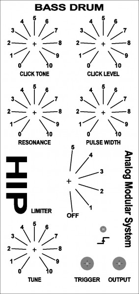
This is what I made off it so far, ready to ets the pcb board and make the front panel.
Grt,
Chris
| Description: |
|
| Filesize: |
40.41 KB |
| Viewed: |
3414 Time(s) |
| This image has been reduced to fit the page. Click on it to enlarge. |

|
| Description: |
|
| Filesize: |
151.91 KB |
| Viewed: |
1229 Time(s) |
| This image has been reduced to fit the page. Click on it to enlarge. |
|
| Description: |
|
| Filesize: |
306.78 KB |
| Viewed: |
1358 Time(s) |
| This image has been reduced to fit the page. Click on it to enlarge. |
|
| Description: |
|
| Filesize: |
142.52 KB |
| Viewed: |
1314 Time(s) |
| This image has been reduced to fit the page. Click on it to enlarge. |
|
|
|
|
Back to top
|
|
 |
ElektroBear
Joined: Feb 07, 2013
Posts: 11
Location: Sweden
|
 Posted: Wed Feb 13, 2013 2:45 pm Post subject: Posted: Wed Feb 13, 2013 2:45 pm Post subject:
|
  |
|
Any chance of getting this to work with a resistor voltage divider.
Iam really not fond of +/- voltage personally i feel if the circuit can work with just positive voltage it should be designed that way.
Although this might just be me not wanting to get a +/- PSU ;D |
|
|
Back to top
|
|
 |
plecko
Joined: Jan 21, 2011
Posts: 5
Location: Brighton, UK
|
|
|
Back to top
|
|
 |
Ruebezahl

Joined: Mar 09, 2014
Posts: 112
Location: Taiwan
Audio files: 4
|
 Posted: Sun Sep 28, 2014 6:34 pm Post subject: Posted: Sun Sep 28, 2014 6:34 pm Post subject:
|
  |
|
I builded this Module after the Layout KRS1972 posted here. Unfortunately its not working yet. Though i am not sure if its the fault of this circuit or the Trigger, wich is not working properly. Maybe you can help me find the error? I try to describe how i trigger it:
The clock is a CD40106, giving out a squarewave with a high of 7,7V(checked it with the multimeter). Afterwards its going through this Gate to Trigger Converter:

I have built just one of the Converters, using just one Half of the Op-Amp, and i obtained the Transistor-parts.
The signal wich comes out of the Converter, when i check it with the multimeter, is just 0,22V! But it could be, that this is just because the high is so short, that the multimeter doesn't have enough time to trace it.
When i listen to the output of the Converter it gives out a click in sync with the clock speed. its as loud as the click from the clock itself, so i think its probably also the same amplitude.
The Bass Drum itself, is giving out mostly Humming, but you can hear the rythm of the clock through it. none of the Controls actually change anything. The Trigger-LED is iluminating with every trigger. But the LEDs mounted to the Limiting-Switch are not glowing.
Do you think the problem is the Drum or the Trigger-part? And any idea on problem shooting?
Thanks a lot
_________________
https://soundcloud.com/ruebezahl |
|
|
Back to top
|
|
 |
Sebo

Joined: Apr 27, 2007
Posts: 564
Location: Argentina
|
 Posted: Mon Sep 29, 2014 11:23 am Post subject: Posted: Mon Sep 29, 2014 11:23 am Post subject:
|
  |
|
For what you said, I'm pretty sure the problem is in the Bass Drum circuit.
Also I think you don't need the gate to trigger converter because the input of the Bass Drum have a very similar circuit...
First try to connect the output of your clock circuit directly to the Bass Drum.
_________________
Sebo
---------------------------------------
My Music:
https://www.facebook.com/cosaquitos/ |
|
|
Back to top
|
|
 |
Ruebezahl

Joined: Mar 09, 2014
Posts: 112
Location: Taiwan
Audio files: 4
|
 Posted: Mon Sep 29, 2014 12:46 pm Post subject: Posted: Mon Sep 29, 2014 12:46 pm Post subject:
|
  |
|
Oh okay, good to know. Seems you are right. at least according to the trigger-LED its working without the Converter-Circuit. Still no Sound though. I am off, troubleshooting  thanks so far! thanks so far!
edit: I found an Error: When i have the drum circuit disconnected from everything, i can measure 10V at the output. when i connect it to the Converter-Circuit, i can just measure 7V. when i connect it straight to the Drum Circuit, the Output-Pulse is just as low as 0,5V.
I placed two resistors as a voltage divider after the clock-output, to lower the pulse to 10V, since 15V (wich is the original amplitude) might be to high. Could this Voltage Divider be the problem? Do i need a more sophisticated way to lower the amplitude of the pulse?
_________________
https://soundcloud.com/ruebezahl |
|
|
Back to top
|
|
 |
|

