| Author |
Message |
VanaVara
Joined: Jan 30, 2012
Posts: 23
Location: Vilnius
|
 Posted: Fri Feb 03, 2012 3:41 am Post subject:
DRUMMACHINE & SEQUENCER Posted: Fri Feb 03, 2012 3:41 am Post subject:
DRUMMACHINE & SEQUENCER
Subject description: CV/Gate, Triggering, Clocks and so on... |
  |
|
Hi guys!
I have a couple of noob questions for you, maybe you can help me out?:)
I'm having hard times understanding all the stuff about CV/Gate, Triggering, Internal Clocks / External Clocks:
How could one connect, let say, drum modules (like these: http://ericarcher.net/devices/tr808-clone/ ) to a sequencer so i could get a drum/rhythm machine, or how to connect the oscillator/noisemachine to a sequencer?
What i would like to build is:
• Kick+Snare+Hihats ---> Sequencer(s) = Drummachine
• OCS (sin/tri/saw) ---> ADRS ---> Sequencer = Melodymachine :)
Are these machines possible to build and how, or maybe there's something essential i don't understand...?
Maybe you can help me out with theoretical background in layman's terms and some schematics/layouts?
Any help is very appreciated!
Thank you in advance:) |
|
|
Back to top
|
|
 |
-minus-
Joined: Oct 26, 2008
Posts: 787
Audio files: 13
|
| Posted: Fri Feb 03, 2012 9:01 am Post subject:
|
|
|
Hi again,
Quite a few questions. I'll try answer them, but there are others here who are far more knowledgeable than me!
The GATE thing is kind of like what it implies. It's like opening a real gate for a period of time, letting something through the gate, then closing it... but in our case, it's not farm animals passing through the gate, it's electricity!  It's sort of like holding your finger on a button for a while then releasing it. It's sort of like holding your finger on a button for a while then releasing it.
The TRIGGER on the other hand is sort of like pulling a trigger on a gun. It's a very quick thing! It's used to switch on other things like drum modules for example.
The CV is a control voltage. So if you have a VCO (voltage controlled oscillator), by sending it some voltage, you can control the pitch for example.
I think your best bet is not to get too advanced right now. I'm not sure how much you know. Before you go creating more complex drum modules, I'd suggest you look at something simpler. Have a look at Eric Archer's Mini Space Rocker circuit:
http://ericarcher.net/devices/mini-space-rockers/
I have built this on stripboard some time ago and it works well. You can trigger it manually with a momentary switch or with a simple sequencer like the Baby 10.
The Baby 10 is quite simple to make. It is based around a decade counter, the 4017 chip. It is basically a chip which has ten outputs which switch on and off in sequence from one to 10. These 10 outputs (gates) are sending voltage out which can be individually adjusted if sent through potentiometers. These voltages can then be sent to a VCO which will produce a series of tones. You could find Baby 10 circuits easily. The 4017 needs a clock of some sort. Often it is a square wave oscillator built from a 555 chip running at a low frequency. This would then be what is considered an INTERNAL clock. The 4017 could be fed a clock from another separate module. This would then be an EXTERNAL clock.
A simple VCO to hook up to a Baby 10 might be the Slacker 4046 VCO:
http://srv2.electro-music.com/forum/topic-33607.html&postorder=asc
You wont need all the resistors going to pin9. Just feed CV directly.
I would recommend heading over to the Lunetta forum and looking at that stuff. Loads of ideas there! Hope this has helped you more than it has confused me! |
|
|
Back to top
|
|
|
emdot_ambient
Joined: Nov 22, 2009
Posts: 667
Location: Frederick, MD
|
| Posted: Fri Feb 03, 2012 10:21 am Post subject:
|
|
|
Building a dedicated drum machine is actually a bit more complicated than building the melody machine you mention. Each drum sound is essentially going to be its own circuit (or module). That's easy enough. But to bring them together as one device, the sequencer you use is going to have to trigger each of the circuits independently. So if you're thinking a 16 step sequencer, you'd have to have a trigger for EACH drum voice for EACH step. (3 drum voices and 16 steps would mean 3 triggers per step, or 48 switches total.)
That can be done off one sequencer, but it's actually not a format that's widely available in the DIY land. Most sequencers out there are limited to 8 steps and one Gate per step.
Note that Gate and Trigger are often used as interchangeable terms. Some modules are able to use both. Some require a true trigger, which is just a very fast spiking voltage as opposed to the on-for-a-while, off-for-a-while nature of gates. You can easily convert a gate output to a trigger, though.
So, for a drum sequencer, you'll need to look for a "Trigger Sequencer" that has one trigger line per drum voice you want to use.
As for your melody machine...there are tons of options out there for that. Take a look in this forum for the SympleSEQ thread. That's about as easy and basic a sequencer option as you'll find: 8 steps per sequencer, one CV and one Gate output.
The basic patch for hooking that up to make melodies would be:
CV output of the sequencer to the Pitch input (often called V/Oct) of your oscillator, and possibly to the Frequency In of a VCF (Voltage Controlled Filter).
Gate output of the sequencer would go to the Gate In of your envelope generator (ADSR).
CV out of the ADSR would go to a VCA (Votage Controlled Amplifier...don't forget this part!), and possibly to the Frequency In of a filter as well.
Oscillator wave out (sine/tri/saw) goes to the In of a filter (it'll sound pretty dull otherwise).
Filter output goes to the audio in of the VCA.
VCA Out goes to your mixer or FX unit (sound output).
So if you look at it in 3 parts (Audio, CV and Gate), it goes like this:
AUDIO
VCO =>VCF=>VCA=>Out to whatever
CV
SEQ=>VCO
SEQ=>VCF (optional)
ADSR=>VCA
GATE
SEQ=>ADSR
SEQ=>VCF (optional)
...and, of course, this is not the only possible or worthwhile signal path. Both CV and Gates can also be used to control VCAs, for example.
_________________
Looking for a certain ratio since 1978 |
|
|
Back to top
|
|
|
VanaVara
Joined: Jan 30, 2012
Posts: 23
Location: Vilnius
|
| Posted: Wed Feb 08, 2012 2:50 am Post subject:
|
|
|
Guys, you are amazing!:)
Thank you so much for a comprehensive explanation, it surpassed all my expectations!
Yesterday i finally completed APC+4017Sequencer (at first it didn't work because i forgot the jumpers under the chips), but as i expected it has the problem with sequencer pots as Minus already wrote --- they are "mute" 2/3 the way round, so it leaves me with very narrow range of pitch change. So now i'm thinking is it the problem with sequencer or the whole circuit? Maybe if i'd build 4017 Sequencer as stand alone with CV out, and connect it to APC with CV in, or whatever VCO, the problems would disappear?
| Quote: | | I think your best bet is not to get too advanced right now. I'm not sure how much you know. Before you go creating more complex drum modules, I'd suggest you look at something simpler. |
Yes, definitely! Those 808 clone drum modules I took just as an example, they are way too complex for me at the moment, it could be as my final goal of DIY drum machine:))) Now i'd take your advice and play around with simple VCO or drum modules, but first i got to re-build 4017 Seq as standalone with CV out...
| Quote: | | So if you're thinking a 16 step sequencer, you'd have to have a trigger for EACH drum voice for EACH step. (3 drum voices and 16 steps would mean 3 triggers per step, or 48 switches total. |
No, 8 step sequencer is OK, no need to get too complex --- 8 STEPS x 3 VOICES drum machine sounds very good to me! But probably i'd start with "melody machine" now --- it is already like rocket science for me:)))
Anyway, any tips or suggestions are welcome --- if you have any links or schematics/layouts of simple/interesting easy to build circuits, post them here!:)
All the best |
|
|
Back to top
|
|
|
emdot_ambient
Joined: Nov 22, 2009
Posts: 667
Location: Frederick, MD
|
|
|
Back to top
|
|
|
VanaVara
Joined: Jan 30, 2012
Posts: 23
Location: Vilnius
|
| Posted: Wed Feb 08, 2012 3:43 pm Post subject:
|
|
|
Yes, but it is like pre-build, ready-made kit, and i would like to build it from scrach with components on the stripboard, just a most basic simple 4017 or Baby or whatever sequencer (as standalone) with CV/Gate output, so i can sequence some VCO module (for a "Melodymachine").
| Quote: | Building a dedicated drum machine is actually a bit more complicated than building the melody machine you mention. Each drum sound is essentially going to be its own circuit (or module). That's easy enough. But to bring them together as one device, the sequencer you use is going to have to trigger each of the circuits independently.
<...>
So, for a drum sequencer, you'll need to look for a "Trigger Sequencer" that has one trigger line per drum voice you want to use. |
Now for a drum sequencer, maybe i could build 3 separate standalone 8 step sequencers for 3 drum modules (Kick+Seq / Snare+Seq / Hat+Seq) and control them all with one external clock making them into ONE rhythm machine, right? Wrong?:) |
|
|
Back to top
|
|
|
-minus-
Joined: Oct 26, 2008
Posts: 787
Audio files: 13
|
| Posted: Thu Feb 09, 2012 1:40 pm Post subject:
|
|
|
A Baby 10 is a very simple sequencer. You don't need a kit to make one.
You can control multiple drum modules from the one 4017 IC, so you don't need multiple IC's running from one common clock. Just feed the outputs of the 4017 through a diode, to a switch so you can turn the beats OFF/ON. You can run multiple diodes and switches from each of the 10 steps, or however many you chose to use.
To get a narrower 'trigger' signal, use a AND gate and feed it with the output of a step AND the clock. Inverting the clock signal first will give you a narrower clock pulse too. |
|
|
Back to top
|
|
|
RF

Joined: Mar 23, 2007
Posts: 1502
Location: Northern Minnesota, USA
Audio files: 28
|
| Posted: Thu Feb 09, 2012 2:18 pm Post subject:
|
|
|
I've been pleased with the use of Lunetta-Type circuits for triggering drums - using just very simple counters, shift registers and dividers to create unique drum patterns...
Here's what I did for the QuadBass++ with simple Logic.
http://www.sdiy.org/rfeng/quad.html
As minus suggests - take a look at the Lunetta forum for how to use these.
bruce
_________________
www.sdiy.org/rfeng
"I want to make these sounds that go wooo-wooo-ah-woo-woo.”
(Herb Deutsch to Bob Moog ~1963) |
|
|
Back to top
|
|
|
VanaVara
Joined: Jan 30, 2012
Posts: 23
Location: Vilnius
|
| Posted: Tue Feb 14, 2012 1:55 pm Post subject:
|
|
|
Hi again!
| Quote: | | As minus suggests - take a look at the Lunetta forum for how to use these. |
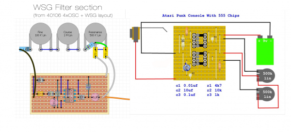
I took your suggestions and was reading Lunetta forum lately --- and i found few things i would like to build, these are Heterodyne Space Explorer and WSG Filter!
First of all i would like to build WSG Filter for my dual 555 Atari Punk Console to play around, found few layouts of WSG (as standalone and as a part of Space Explorer) and I would like to ask your help --- could you guys draw on the layouts how should i connect my APC with WSG? (see attached below) Does audio from APC goes to WSG instead of audio output? Should they both powered separately? What parts should be discarded? Sorry these are silly questions i know, but i'm very new into electronix...
| Quote: | | A Baby 10 is a very simple sequencer. You don't need a kit to make one. |
Maybe you guys could draw/link the stripboard layout for this Standalone Baby 8/10 with 555 clock , i'm not good at reading schematics yet... 
Thank you for your time, guys!
I really appreciate your help
| Description: |
|
| Filesize: |
352.45 KB |
| Viewed: |
1371 Time(s) |
| This image has been reduced to fit the page. Click on it to enlarge. |

|
| Description: |
|
| Filesize: |
394.69 KB |
| Viewed: |
773 Time(s) |
| This image has been reduced to fit the page. Click on it to enlarge. |
|
|
|
|
Back to top
|
|
|
bikini-inspector
Joined: Nov 29, 2007
Posts: 16
Location: bremen
|
| Posted: Tue Feb 14, 2012 5:39 pm Post subject:
|
|
|
nice choice! APC+WSGfilter are pretty much what i did and it sounds great!
no need for a drawing: the output of the APC goes to the INPUT of the filter (blue wire in my layout).
the black wire from the apc's output goes to GND of the filter.
or, you could wire up input and output jacks to the filter to keep the possibility for use with other gear.
Funny, this afternoon i added a 1/4 jack to my box to do just that 
i like your thinking with the sequencer: several BUSes to control several voices! |
|
|
Back to top
|
|
|
VanaVara
Joined: Jan 30, 2012
Posts: 23
Location: Vilnius
|
| Posted: Wed Feb 15, 2012 1:18 am Post subject:
|
|
|
| bikini-inspector wrote: | no need for a drawing: the output of the APC goes to the INPUT of the filter (blue wire in my layout).
the black wire from the apc's output goes to GND of the filter. |
So where does the GROUND comes from to WSG Output? (in your layout there is only one wire for Output shown)
| bikini-inspector wrote: | | or, you could wire up input and output jacks to the filter to keep the possibility for use with other gear. |
This is more appealing option but even more complicated to me --- ok so APC doesn't change at all, but what about WSG --- it is powered separately (9V RED and Ground BLACK), but where does the Ground wire comes from to connect to Input and Output jacks --- same way as in APC, directly from battery?
In short, i'm confused about IN and OUT of WSG Filter, because only ONE wire for each is shown... |
|
|
Back to top
|
|
|
bikini-inspector
Joined: Nov 29, 2007
Posts: 16
Location: bremen
|
| Posted: Wed Feb 15, 2012 8:03 am Post subject:
|
|
|
hi
usually, in 9V circuits like these, only one wire is drawn. This is because when you wire up a jack, the second wire is always ground. (if not, you will be told)
It doesn't really matter where you take that ground from, it can be the battery or some place on the circuit board.
same goes for connections without jacks, but when you power 2 circuits from the same battery, the grounds ARE already connected (via the battery), so you would just have to wire up the signal wire.
i've added jacks to your drawing using the bottom row of the stripboard. As you can see, there is plenty of room for ground connections.
| Description: |
|
| Filesize: |
504.79 KB |
| Viewed: |
1242 Time(s) |
| This image has been reduced to fit the page. Click on it to enlarge. |

|
|
|
|
Back to top
|
|
|
defog

Joined: Aug 24, 2011
Posts: 113
Location: Philadelphia
|
| Posted: Wed Feb 15, 2012 11:16 am Post subject:
|
|
|
Not to overly complicate things, but you could also make a very simple drum triggering device with an Arduino. You'd be able to trigger drum modules via midi notes fairly easily, unless you want a traditional-style sequencer. I have examples and code if you're interested.
_________________
The Phoenix Vertigo is my Electronic alias. Check out my songs on soundcloud : http://soundcloud.com/charles-stieg/ |
|
|
Back to top
|
|
|
Cynosure
Site Admin

Joined: Dec 11, 2010
Posts: 1025
Location: Toronto, Ontario - Canada
Audio files: 82
|
| Posted: Wed Feb 15, 2012 6:43 pm Post subject:
|
|
|
Defog - I am interested in that. If I can make it give 5V trigger pulses then it could drive the circuits i made for me drum machine. Please share.
_________________
JacobWatters.com |
|
|
Back to top
|
|
|
bikini-inspector
Joined: Nov 29, 2007
Posts: 16
Location: bremen
|
| Posted: Thu Feb 16, 2012 4:51 am Post subject:
|
|
|
diddely-ditto!
seems like a convenient way to back up the weak monotribe drums with diy modules. |
|
|
Back to top
|
|
|
VanaVara
Joined: Jan 30, 2012
Posts: 23
Location: Vilnius
|
| Posted: Thu Feb 16, 2012 8:10 am Post subject:
|
|
|
Thanx, bikini-inspector! Yesterday I build APC+WSG and it's working like a charm!
Now i would like to integrate LFO to this circiut to modulate APC 
I found this simple LFO layout: http://electro-music.com/forum/topic-30456.html
My question is --- how to connect this LFO to APC? Where does the LFO output goes to? |
|
|
Back to top
|
|
|
defog
Joined: Aug 24, 2011
Posts: 113
Location: Philadelphia
|
| Posted: Thu Feb 16, 2012 8:21 am Post subject:
|
|
|
Here is a wiring diagram I just whipped this up real fast to illustrate the number of parts and basic wiring. There may be errors, so proceed with caution. I've always just perfboarded these when I needed them.

Here is the code by Kuki. I did not write this code, I just modified it for my own purposes. There are two versions of this code that I have used. The first illustrated here was used in a Sound Master Rhythm 1 drum machine that didn't have critical trigger timings. The drum sound duration was not dependent on the length of the trigger pulse, it simply needed a High state to trigger. Therefore, this code just sets a digital pin to note on = HIGH Note-off=LOW. NOTE - this code breaks in the most recent version of Arduino because "BYTE" is no longer supported. You'd have to rewrite it to use Serial.Write instead if you want to use a version later than 0021
| Code: |
/* Midi In Basic 0.2 // kuki 8.2007
*
* -----------------
* listen for midi serial data, and light leds for individual notes
IMPORTANT:
your arduino might not start if it receives data directly after a reset, because the bootloader thinks you want to uplad a new progam.
you might need to unplug the midi-hardware until the board is running your program. that is when that statusLed turns on.
#####################################################################################################################################################
SOMETHING ABOUT MIDI MESSAGES
midi messages start with one status byte followed by 1 _or_ 2 data bytes, depending on the command
example midi message: 144-36-100
the status byte "144" tells us what to do. "144" means "note on".
in this case the second bytes tells us which note to play (36=middle C)
the third byte is the velocity for that note (that is how powerful the note was struck= 100)
example midi message: 128-36
this message is a "note off" message (status byte = 128). it is followed by the note (data byte = 36)
since "note off" messages don't need a velocity value (it's just OFF) there will be no third byte in this case
NOTE: some midi keyboards will never send a "note off" message, but rather a "note on with zero velocity"
do a web search for midi messages to learn more about aftertouch, poly-pressure, midi time code, midi clock and more interesting things.
#####################################################################################################################################################
HARDWARE NOTE:
The Midi Socket is connected to arduino RX through an opto-isolator to invert the midi signal and seperate the circuits of individual instruments.
connect 8 leds to pin2-pin9 on your arduino.
####################################################################################################################################################
*/
//variables setup
byte incomingByte;
byte note;
byte velocity;
int statusLed = 13; // select the pin for the LED
int action=2; //0 =note off ; 1=note on ; 2= nada
long previousMillis = 0; // Store value of last time trigger was sent
long interval = 10; // Duration at which to hold trigger
//setup: declaring iputs and outputs and begin serial
void setup() {
pinMode(statusLed,OUTPUT); // declare the LED's pin as output
pinMode(2,OUTPUT);
pinMode(3,OUTPUT);
pinMode(4,OUTPUT);
pinMode(5,OUTPUT);
pinMode(6,OUTPUT);
pinMode(7,OUTPUT);
pinMode(8,OUTPUT);
pinMode(9,OUTPUT);
//start serial with midi baudrate 31250 or 38400 for debugging
Serial.begin(31250);
digitalWrite(statusLed,HIGH);
}
//loop: wait for serial data, and interpret the message
void loop ()
{
unsigned long currentMillis = millis();
if (currentMillis - previousMillis > interval) {
previousMillis = currentMillis;
if (Serial.available() > 0) {
// read the incoming byte:
incomingByte = Serial.read();
// wait for as status-byte, channel 1, note on or off
if (incomingByte== 144){ // note on message starting starting
action=1;
}else if (incomingByte== 128){ // note off message starting
action=0;
}else if (incomingByte== 208){ // aftertouch message starting
//not implemented yet
}else if (incomingByte== 160){ // polypressure message starting
//not implemented yet
}else if ( (action==0)&&(note==0) ){ // if we received a "note off", we wait for which note (databyte)
note=incomingByte;
playNote(note, 0);
note=0;
velocity=0;
action=2;
}else if ( (action==1)&&(note==0) ){ // if we received a "note on", we wait for the note (databyte)
note=incomingByte;
}else if ( (action==1)&&(note!=0) ){ // ...and then the velocity
velocity=incomingByte;
playNote(note, velocity);
note=0;
velocity=0;
action=0;
}else{
//nada
}
}
}
}
void blink(){
digitalWrite(statusLed, HIGH);
delay(100);
digitalWrite(statusLed, LOW);
delay(100);
}
void playNote(byte note, byte velocity){
int value=LOW;
if (velocity >10){
value=HIGH;
if (previousMillis>interval)
value=LOW;
}else{
value=LOW;
}
//since we don't want to "play" all notes we wait for a note between 36 & 44
if(note>=36 && note<44){
byte myPin=note-34; // to get a pinnumber between 2 and 9
digitalWrite(myPin, value);
}
}
|
_________________
The Phoenix Vertigo is my Electronic alias. Check out my songs on soundcloud : http://soundcloud.com/charles-stieg/ |
|
|
Back to top
|
|
|
defog
Joined: Aug 24, 2011
Posts: 113
Location: Philadelphia
|
| Posted: Thu Feb 16, 2012 8:21 am Post subject:
|
|
|
A simple modification to change the pulse-length would be to do something like this:
| Code: |
if(note>=36 && note<44){
byte myPin=note-34;
digitalWrite(myPin, value);
delay(X); // Where X is the millisecond delay time. 10 seems to work well in a lot of drum machines.
digitalWrite(myPin, LOW);
}
|
However, using the delay function will introduce timing issues with the output, so you'd want to use the millis function instead with a timing variable.
_________________
The Phoenix Vertigo is my Electronic alias. Check out my songs on soundcloud : http://soundcloud.com/charles-stieg/ |
|
|
Back to top
|
|
|
defog
Joined: Aug 24, 2011
Posts: 113
Location: Philadelphia
|
|
|
Back to top
|
|
|
bikini-inspector
Joined: Nov 29, 2007
Posts: 16
Location: bremen
|
| Posted: Thu Feb 16, 2012 8:30 am Post subject:
|
|
|
cheers defog, i will check that out, very cool!
but back to topic:
haha, well that sounds very familiar, check out my box http://vimeo.com/26630135
not sure where to connect the LFO on your APC, as i've built the 556 version.
in general, the apc offers 3 options:
modulate pitch
modulate pulse width
gate (this means as long as a voltage is applied to the reset pin, sound plays)
on the 556, the pins are 3 and 11 for CV and pin 4 for gate.
I'd suggest you just build the LFO and just poke the output around on the APC board to find the sweet spots.
and as always: why not connect these spots to extrenal jacks, so once you've built a sequencer, you can easily interface your stuff  |
|
|
Back to top
|
|
|
VanaVara
Joined: Jan 30, 2012
Posts: 23
Location: Vilnius
|
| Posted: Thu Feb 16, 2012 10:23 am Post subject:
|
|
|
| bikini-inspector wrote: |
I'd suggest you just build the LFO and just poke the output around on the APC board to find the sweet spots. |
Probably i'll take your suggestion and play around with LFO poking around APC as soon as i build one:)
Dude, your machine is amazing, this is what i was talking about! --- maybe you could post some layouts to study how everything is connected together?:) What LFO did you use here? LFO Layout?
| bikini-inspector wrote: | | and as always: why not connect these spots to extrenal jacks, so once you've built a sequencer, you can easily interface your stuff ;) |
| Quote: | | A Baby 10 is a very simple sequencer. You don't need a kit to make one. |
By the way, talking about the Sequencer --- could you guys anyone post / link / draw a working stripboard layout of this Baby Sequencer? (maybe correct this one or something similar: http://electro-music.com/forum/post-343100.html ) because i cannot find any proper layout of this sequencer on this forum nor on the web...? I'm dying to build one as standalone with CV out to sequence APC or any other oscillator:)
Thanx! |
|
|
Back to top
|
|
|
Cynosure
Site Admin
Joined: Dec 11, 2010
Posts: 1025
Location: Toronto, Ontario - Canada
Audio files: 82
|
| Posted: Sat Feb 18, 2012 4:58 am Post subject:
|
|
|
Sorry to be hijacking this thread for arduino stuff...
defog - Thanks for posting that. I have a few questions since I don't have an arduino yet, but I will get one soon if your code is capable of doing what I need. Please let me know what it can do from the following list:
-Trigger drum sounds that require a 5V pulse.
-Trigger multiple drums sounds simultaneously (at least 5).
-Be controlled over midi using Ableton Live and similar software (not running arduino app).
-Be controlled using a standard midi jack.
Preferably I could assign C1-G1 to each trigger a different sound and play the notes using any midi device (synth, software, sequencer).
_________________
JacobWatters.com |
|
|
Back to top
|
|
|
defog
Joined: Aug 24, 2011
Posts: 113
Location: Philadelphia
|
| Posted: Mon Feb 20, 2012 8:20 am Post subject:
|
|
|
| Cynosure wrote: | Please let me know what it can do from the following list:
-Trigger drum sounds that require a 5V pulse.
-Trigger multiple drums sounds simultaneously (at least 5).
-Be controlled using a standard midi jack.
|
5v Trigger pulses, up to 11 of them simultaneously over a standard midi jack. Only 2 pins are reserved for the Midi Data (pins 0 and 1, TX, RX)
| Quote: |
-Be controlled over midi using Ableton Live and similar software (not running arduino app).
|
If you don't plan on using this with anything other than a computer, then consider controlling the midi data via the build-in USB on the arduino. That way you wouldn't even have to build an external stand-alone board for it or bother with the midi jack or opto-isolator. You would just use the actual arduino unit to control things in ableton. This will also allow you to experiment with fun external control devices over the 6 analog input pins, like Piezo triggers, Photocells, microphones, etc.
_________________
The Phoenix Vertigo is my Electronic alias. Check out my songs on soundcloud : http://soundcloud.com/charles-stieg/ |
|
|
Back to top
|
|
|
bikini-inspector
Joined: Nov 29, 2007
Posts: 16
Location: bremen
|
| Posted: Thu Mar 01, 2012 6:20 pm Post subject:
|
|
|
so...any progress on this?
sorry i got no schems for you, this was pretty much pieced together....the LFO i used is linked in the video comments. it hooks up to the aforementioned pins on the apc.
any samples/vids ?
btw: thanks defog, i saved that stuff for later |
|
|
Back to top
|
|
|
VanaVara
Joined: Jan 30, 2012
Posts: 23
Location: Vilnius
|
| Posted: Fri Mar 02, 2012 3:37 am Post subject:
|
|
|
| bikini-inspector wrote: | | so...any progress on this? |
Well, i haven't build LFO yet, but i have build Heterodyne Space Explorer + WSG Filter and i really love its sounds!:) Probably i'll get back to LFO stuff next week. By the way guys, i have came upon Nicolas mini-modular designs ( http://electro-music.com/forum/topic-34550.html ), all seems pretty simple, but i don't understand how to power the circuit with TWO batteries (+9, -9, Ground) --- could you please explain me or link layout?:)
Thanks, i'll have a look!
One more thing guys --- as i started to think about building all these Nicolas "modular" parts (VCO, VCF, ADSR...) and connect them into one "synth", i'll definitely need a KEYBOARD!:) So, i have old russian analog organ synth ЭЛЕКТРОНИКА ЭМ-14 VENTA http://m.matrixsynth.com/2010/12/elektronika-em-14-vintage-soviet-analog.html but i dont use it lately, so maybe i could open its case and somehow connect its keyboard to control my VCOs and stuff? Could work? It would be great to have all these little modules build in old synth case and running on its keyboard, would look like really lovely:) |
|
|
Back to top
|
|
|
|

 Forum index » DIY Hardware and Software
