| Author |
Message |
nathanxl
Joined: Apr 24, 2012
Posts: 77
Location: Wa
|
 Posted: Sat Apr 05, 2014 6:57 am Post subject: Posted: Sat Apr 05, 2014 6:57 am Post subject:
|
  |
|
Hi. Ive been away all summer(winter for you in the north).
The workshop is now cool enough to work in.
Ive just bought a bunch of MC14557 chips and want to try out this circuit.
While Im waiting for them to arrive, could you smart fellows perhaps shed some light on whats going on.?..
Using all of the 64bits how many gate will this get me?
Am I correct that it will allow me 64 gates passing through it and then loop them?
Sorry if this is a silly question. |
|
|
Back to top
|
|
 |
noto

Joined: Nov 05, 2009
Posts: 24
Location: portland
|
|
|
Back to top
|
|
|
billsship

Joined: Apr 14, 2013
Posts: 21
Location: Arkansas, USA
|
| Posted: Wed Jun 18, 2014 9:44 pm Post subject:
|
|
|
Is there a way to clear the 4031's 'memory' quicker than holding down normally-on button for the duration of it's cycle?
I'm wondering if cutting off pin 16 (+V) momentarily would help it forget.
The reason being, if feeding slower clocks into this thing, 64 steps might take a while to cycle through.
_________________
Vine username: "billsship"
Modulargrid |
|
|
Back to top
|
|
|
noto
Joined: Nov 05, 2009
Posts: 24
Location: portland
|
| Posted: Wed Jun 18, 2014 10:11 pm Post subject:
|
|
|
| for mine, I used a 'step-erase' switch to delete steps incrementally, and a 'quick-erase' switch that opened the loop while switching the input clock to another one that was set to a significantly higher frequency. one short press and the whole sequence is gone. if you just turn the power off, some of the bits will still be stored when you power back up. I found it necessary to build an 'initial-clear' circuit and a flip flop to keep the loop open upon power up, but then closed when a 'write' signal is sensed. |
|
|
Back to top
|
|
|
billsship
Joined: Apr 14, 2013
Posts: 21
Location: Arkansas, USA
|
| Posted: Wed Jun 18, 2014 10:47 pm Post subject:
|
|
|
| noto wrote: | | for mine, I used a 'step-erase' switch to delete steps incrementally, and a 'quick-erase' switch that opened the loop while switching the input clock to another one that was set to a significantly higher frequency. one short press and the whole sequence is gone. if you just turn the power off, some of the bits will still be stored when you power back up. I found it necessary to build an 'initial-clear' circuit and a flip flop to keep the loop open upon power up, but then closed when a 'write' signal is sensed. |
Clever!! So, I'm guessing you manually advanced the clock input with a pushbutton, and if you saw that the bit was high, you would press the clear button?
Your way of switching to a fast clock to quickly cycle through an clear the bits, I think that's a really great idea. However, I plan on using an external clock for this. Maybe I could have a simple 40106 on board for this duty alone.
Also - did you incorporate some type of reset into this? Or did you consider any step the 1st step if they were all cleared?
_________________
Vine username: "billsship"
Modulargrid |
|
|
Back to top
|
|
|
roglok

Joined: Aug 28, 2010
Posts: 202
Location: uptown
|
| Posted: Fri Jan 16, 2015 7:54 am Post subject:
|
|
|
| this is really interesting! is there a way to reset the loop sequence? |
|
|
Back to top
|
|
|
SUGARAT
Joined: Jan 21, 2015
Posts: 19
Location: California
Audio files: 1
|
| Posted: Fri Jan 23, 2015 1:00 pm Post subject:
|
|
|
No reset or inhibit pin on the 4031. That's too bad because there is plenty of room for one. As stated above the quickest way to clear the loop is probably to switch the clock to a really fast one while keeping data low. Sort of like erasing a tape loop. You hit record and turn up the motor speed.
Also, with enough stages you should be able to loop audio not just control signals, no? you would just be limited to as many cycles as there are stages in the shift register. also frequencies above the clock frequency won't playback properly. |
|
|
Back to top
|
|
|
PHOBoS

Joined: Jan 14, 2010
Posts: 5980
Location: Moon Base
Audio files: 709
|
| Posted: Sun Jul 24, 2016 8:59 am Post subject:
|
|
|
I finally got my hands on some CD4031s to built my own TAP looper.  But there was one thing I didn't really like about the original circuit; But there was one thing I didn't really like about the original circuit;
the not so standard Normally Closed switch, and the fact that it is placed within the data line so it can't be controlled by other logic. But after
studying the datasheet I figured out a way to use a more standard Normally Open switch. And because it is connected between GND and a pin
of the CD4031 it can now be controlled by other logic. The discrete OR gate (diodes + resistor) add the WRITE signal to the output so you can
directly see/hear what you are doing.
I also designed a deluxe version which has a nicer output in the form of an actual logic gate and it also sends the ERASE signal through to the
output. The spare NOR is used to drive an LED.
And I designed a stripboard layout for the deluxe version for those who like to use that.
| Description: |
|
| Filesize: |
30.56 KB |
| Viewed: |
1065 Time(s) |
| This image has been reduced to fit the page. Click on it to enlarge. |
|
| Description: |
|
| Filesize: |
40.6 KB |
| Viewed: |
1037 Time(s) |
| This image has been reduced to fit the page. Click on it to enlarge. |
|
| Description: |
|
| Filesize: |
17.68 KB |
| Viewed: |
880 Time(s) |
| This image has been reduced to fit the page. Click on it to enlarge. |
|
_________________
"My perf, it's full of holes!"
http://phobos.000space.com/
SoundCloud BandCamp MixCloud Stickney Synthyards Captain Collider Twitch YouTube |
|
|
Back to top
|
|
|
dk
Joined: Feb 12, 2019
Posts: 115
Location: Europe
|
| Posted: Sun Dec 01, 2019 4:24 pm Post subject:
|
|
|
| Just a quick question... to debounce the switches on these, would it be as simple as strapping a cap (100nF?) over the switch contacts? |
|
|
Back to top
|
|
|
PHOBoS
Joined: Jan 14, 2010
Posts: 5980
Location: Moon Base
Audio files: 709
|
| Posted: Sun Dec 01, 2019 4:46 pm Post subject:
|
|
|
hmm, the circuit somewhat debounces itself unless you run it at a very high frequency because bits are only added/removed on
a low-to-high transition of the clock. However because it also routes the switches to the outputs bouncing can occur here.
A simple capacitor can sometimes improve things but can also make it worse. With these digital circuits you want transitions
to be as fast as possible, so no rising/falling slopes. Ideally you would use an RC low pass filter followed by a schmitt trigger or
comparator with hysteresis after the switch. It depends a lot on the switches you use though and what you are triggering with
the output. Something like a drummodule or envelope generator will be more forgiving than a clock input.
_________________
"My perf, it's full of holes!"
http://phobos.000space.com/
SoundCloud BandCamp MixCloud Stickney Synthyards Captain Collider Twitch YouTube |
|
|
Back to top
|
|
|
dk
Joined: Feb 12, 2019
Posts: 115
Location: Europe
|
| Posted: Sun Dec 01, 2019 4:54 pm Post subject:
|
|
|
Ah yes... the 4031 doesn't seem to mind my switches, but one of the cool things about your setup with the switches passing through to the output, so when I'm not using the looper, I can still use the switches as a manual trigger. Sometimes they can be a bit wonky this way 
I take it, then, that the best way to resolve this is with a similar setup to the one you added to someone else's design here: http://electro-music.com/forum/phpbb-files/button_gated_oscillator_127.gif ? |
|
|
Back to top
|
|
|
PHOBoS
Joined: Jan 14, 2010
Posts: 5980
Location: Moon Base
Audio files: 709
|
|
|
Back to top
|
|
|
dk
Joined: Feb 12, 2019
Posts: 115
Location: Europe
|
| Posted: Mon Dec 02, 2019 9:22 am Post subject:
|
|
|
| Cool, thanks for posting that! |
|
|
Back to top
|
|
|
cyclic

Joined: Mar 15, 2015
Posts: 95
Location: hobart
|
| Posted: Wed Dec 11, 2019 12:55 am Post subject:
|
|
|
What am I missing here?
How the hell is this not as well known as the baby8 or APC etc as a super simple beginner circuit. It seems to achieve functionality vs size beyond either of those two as well.
Is there some major weakness which I've missed? |
|
|
Back to top
|
|
|
PHOBoS
Joined: Jan 14, 2010
Posts: 5980
Location: Moon Base
Audio files: 709
|
| Posted: Wed Dec 11, 2019 6:30 am Post subject:
|
|
|
heh, there are a lot of interesting simple circuits posted on this forum that aren't well known, especially in this 'lunetta' section.
It might be because this forum isn't visited enough for them to spread and personally I don't really hang out anywhere else.
As for this circuit in particular the 4031 can be difficult to get.
The 4089 is another very interesting CMOS IC but also hard to obtain.
_________________
"My perf, it's full of holes!"
http://phobos.000space.com/
SoundCloud BandCamp MixCloud Stickney Synthyards Captain Collider Twitch YouTube |
|
|
Back to top
|
|
|
cyclic
Joined: Mar 15, 2015
Posts: 95
Location: hobart
|
| Posted: Thu Dec 12, 2019 3:53 pm Post subject:
|
|
|
I'm doing an order soon and mouser has the 4031 at $2.50 which is...ok..so I reckon I'll get one.
Have you Daisy chained them ever for 128 steps? I can see how it seems to be used at a high rate and is only nominally 64steps for our use, and I assume this means max 32 square gates with an on Off cycle, which is then run pretty fast for long/multiple gates. So I figure 128 doubles the resolution if not the functional number of gates.
If it's trivial I'd get 2 and design a PCB for them...
And 4089: subharmonics by the note rather then octave? Eg subharmonics 5th? |
|
|
Back to top
|
|
|
PHOBoS
Joined: Jan 14, 2010
Posts: 5980
Location: Moon Base
Audio files: 709
|
| Posted: Fri Dec 13, 2019 4:21 pm Post subject:
|
|
|
yes, you can chain them. I was actually working on a version that could switch between 2 seperate 64 step ones or one 128 step one.
The design I have needs a 4-throw switch so I ordered a rotary switch for it but by the time I got it I was already working on some other
things so I never tested it.
The frequency you use depends on how you want to use it. The orginal idea is to run it at a high frequency so the timing will be close to the
'rhythm' you tap. So yes, if you use 128 steps (and double the frequency) you will get a higher resolution. It can also be used at slow
frequencies though and you could 'program' the sequence step by step. (wasn't that a 90's TV show ?)
I don't think the outputs of the 4089 are musical/tonal although I didn't check if there is a fifth in there. But it is great for creating interesting
rhythms. (see also this circuit)
btw. if you order from mouser I would order at least 1 extra in case you blow it 
_________________
"My perf, it's full of holes!"
http://phobos.000space.com/
SoundCloud BandCamp MixCloud Stickney Synthyards Captain Collider Twitch YouTube |
|
|
Back to top
|
|
|
cyclic
Joined: Mar 15, 2015
Posts: 95
Location: hobart
|
| Posted: Fri Dec 13, 2019 6:39 pm Post subject:
|
|
|
Re: the 4031, so did you ever get a confirmed schematic? If you've got an eagle file I'll work on a PCB for it. I AM trying to do all PCBs not protoboard these days because my synth has to survive being strapped on the front of my bike and vibration breakages have occured most inopportunely...
Re: the 4089, nah I looked at the ratios and since its a /16 the only true harmonic ratio it will do is a perfect 4th and suboctave. So sounds better for patterns and weird noises than chords. Not that I'm at all against patterns and weird noises! |
|
|
Back to top
|
|
|
Top Top

Joined: Feb 02, 2010
Posts: 266
Location: California
|
| Posted: Tue Dec 17, 2019 5:53 pm Post subject:
|
|
|
| cyclic wrote: | What am I missing here?
How the hell is this not as well known as the baby8 or APC etc as a super simple beginner circuit. It seems to achieve functionality vs size beyond either of those two as well.
Is there some major weakness which I've missed? |
The main difference with something like the baby 8 is that you can set different CV levels on a baby 8. This is just trigger/gate outputs.
One really cool expansion of this circuit which I would like to do eventually is to have three 4031 loopers in parallel (with a common clock), feeding the data inputs of a CD4051, switching between 8 different pots setting CV values (or resistance values on a simple RC CMOS oscillator). You could then feed an 8 note keyboard (with 3 bit decoding) or a 3 bit pushbutton input to the 4031s and you could create 64 step CV sequences with a very simple/minimal control interface (limited to 8 potential CV values of course).
_________________
∆ A.M.P. ESOTERIC ELECTRONICS ∆ |
|
|
Back to top
|
|
|
cyclic
Joined: Mar 15, 2015
Posts: 95
Location: hobart
|
| Posted: Wed Dec 18, 2019 1:41 pm Post subject:
|
|
|
| Top Top wrote: | | cyclic wrote: | What am I missing here?
How the hell is this not as well known as the baby8 or APC etc as a super simple beginner circuit. It seems to achieve functionality vs size beyond either of those two as well.
Is there some major weakness which I've missed? |
The main difference with something like the baby 8 is that you can set different CV levels on a baby 8. This is just trigger/gate outputs.
One really cool expansion of this circuit which I would like to do eventually is to have three 4031 loopers in parallel (with a common clock), feeding the data inputs of a CD4051, switching between 8 different pots setting CV values (or resistance values on a simple RC CMOS oscillator). You could then feed an 8 note keyboard (with 3 bit decoding) or a 3 bit pushbutton input to the 4031s and you could create 64 step CV sequences with a very simple/minimal control interface (limited to 8 potential CV values of course). |
Oh yeah I get the difference. I really meant that the APC Is a simple beginner oscillator with weird features, and the baby 8 is a simple seq with, well, no features (they were actually my first 2 projects in about 2014-5) and this tap looper is a simple rhythm generator with way more coolness than a simple clock. I think it would have complimented the baby8 and APC beautifully back then for me. It took me ages to build clock dividers and logic gates and they still don't give the flexibility this does.
And I still want one now even with my way more sophisticated setup.
Anyway, I still don't really get these chips and how they are used but I do like your 64 step seq idea. I can't imagine it would be easy to consistently program without at least having switches options between a tap looper and a simple clock. I imagine that it might be a bit similar to the 'gate divider into a DC mixer' type of sequencing?
Cheers
Lance |
|
|
Back to top
|
|
|
Top Top
Joined: Feb 02, 2010
Posts: 266
Location: California
|
| Posted: Wed Dec 18, 2019 2:33 pm Post subject:
|
|
|
| cyclic wrote: |
Anyway, I still don't really get these chips and how they are used but I do like your 64 step seq idea. I can't imagine it would be easy to consistently program without at least having switches options between a tap looper and a simple clock. I imagine that it might be a bit similar to the 'gate divider into a DC mixer' type of sequencing?
|
The 4031 is basically a logic delay line. So you have a clock, a data input, and a data output. Whatever is on the data input when the clock goes high is recorded into "memory," and is shifted down the delay line until 64 clicks of the clock later, it comes out the output.
In this circuit, that output is simply routed back into the input (along with whatever external data source you are feeding into it), so it just keeps repeating what is fed into it, until the data stream of output is disconnected from the input.
_________________
∆ A.M.P. ESOTERIC ELECTRONICS ∆ |
|
|
Back to top
|
|
|
PHOBoS
Joined: Jan 14, 2010
Posts: 5980
Location: Moon Base
Audio files: 709
|
|
|
Back to top
|
|
|
cyclic
Joined: Mar 15, 2015
Posts: 95
Location: hobart
|
| Posted: Wed Dec 18, 2019 5:42 pm Post subject:
|
|
|
So Tip Top,
I'm trying to understand. <And>
Your 8 key entry pad isnt 8 notes, it's just 8 buttons that each are encoded into 3 bits as high or low. Which means in practice you can encode one step across all 3 4031s with a single key entry.
And this combination then is the data input for another shift register which has 8 individual outputs? Does the 4051 then just give a single output based on the inputs <aaaah> So.... This process encodes those 8 switches to 3 bit binary which is saved as a 64 gate sequence by 3 4031s which then sends their 3 bits back to the 4051 which decodes it back to the 8 pots for cv output...
Did I get it?
Cheers
Lance |
|
|
Back to top
|
|
|
Top Top
Joined: Feb 02, 2010
Posts: 266
Location: California
|
| Posted: Thu Dec 19, 2019 12:05 am Post subject:
|
|
|
| cyclic wrote: | So Tip Top,
I'm trying to understand. <And>
Your 8 key entry pad isnt 8 notes, it's just 8 buttons that each are encoded into 3 bits as high or low. Which means in practice you can encode one step across all 3 4031s with a single key entry.
And this combination then is the data input for another shift register which has 8 individual outputs? Does the 4051 then just give a single output based on the inputs <aaaah> So.... This process encodes those 8 switches to 3 bit binary which is saved as a 64 gate sequence by 3 4031s which then sends their 3 bits back to the 4051 which decodes it back to the 8 pots for cv output...
Did I get it?
Cheers
Lance |
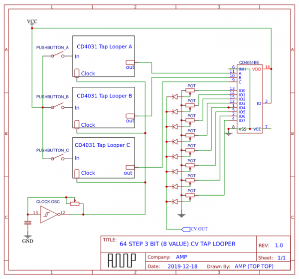
I think it would make more sense if I just drew a diagram. In this diagram, I have three buttons to enter the "notes" for the sequencer to play.
I think it sounds like you get the basic idea from what you said though.
Selecting different combinations of the three data inputs A,B,C, you get 8 possible values(000, 001, 010, 011, 100, 101, 110, 111). So you would tap in your entries just like the regular tap looper, but the three loopers in parallel allow for selecting between 8 tuned CV values (it switches between 8 pots).
The advantage of this over something like the baby 8 is that a baby 8 only has 8 CV values AND only 8 steps. This would still have only 8 possible CV values, but 64 steps, so you could arrange those 8 values in any order (including repeating values if desired) and develop much longer/complex sequences than on a baby 8, and you can rhythmically enter them yourself by taping, as is the enjoyable thing to do with the tap looper.
The 3 pushbutton (3 bit) entry pad could be replaced with an 8 button entry, diode mixing them to the proper combinations of the 3 bits going to the three CD4031 loopers.
Also, you could just put a simple RC oscillator (such as a CD40106 single gate oscillator) right there in the 4051 loop, so that rather than outputting CV, you would be selecting resistance values tuned to "notes" on the built in audio oscillator.
| Description: |
|
| Filesize: |
62.4 KB |
| Viewed: |
384 Time(s) |
| This image has been reduced to fit the page. Click on it to enlarge. |
|
_________________
∆ A.M.P. ESOTERIC ELECTRONICS ∆ |
|
|
Back to top
|
|
|
PHOBoS
Joined: Jan 14, 2010
Posts: 5980
Location: Moon Base
Audio files: 709
|
|
|
Back to top
|
|
|
|

 Forum index » DIY Hardware and Software » Lunettas - circuits inspired by Stanley Lunetta