| Author |
Message |
sneakthief

Joined: Jul 24, 2006
Posts: 569
Location: Berlin
|
 Posted: Fri Feb 07, 2014 7:04 am Post subject:
DIY Euclidean Polyrhythm Generator Posted: Fri Feb 07, 2014 7:04 am Post subject:
DIY Euclidean Polyrhythm Generator
Subject description: for ~$20 |
  |
|
Overview:
A couple a years ago, a guy called Tombola made a Euclidean Polyrhythm generator for Arduino. The documentation was very sparse and the code was rough: http://www.muffwiggler.com/forum/topic-45485.html
Here's the original video demo from then:
I cleaned up Tombola's code somewhat, added Offset controls and imported a much better encoder-reading library. Now the encoders work great! I also made a schematic and included much-needed diode input-protection.
[FEB 2015 UPDATE]
User Interface:
When the rhythms are playing, the display flips between page 1 (steps 1-8 ) and page 2 (steps 9-16).
Here's what the display shows...
Row 1: What step is Output 1 playing
Row 2: Output 1 Pattern (steps 1-8 or 9-16)
Row 3: What step is Output 2 playing
Row 4: Output 2 Pattern (steps 1-8 or 9-16)
Row 5: What step is Output 3 playing
Row 6: Output 3 Pattern (steps 1-8 or 9-16)
Row 7: Which channel is selected
- 2 dots on the left for Channel 1
- 2 dots in the middle for Channel 2
- 2 dots on the right for Channel 3
Row 8: Current triggers
1. Input trigger
2. -
3. Output 1 trigger
4. Output 1 off-beat trigger (all the steps when Output 1 isn't playing)
5. Output 2 trigger
6. -
7. Output 3 trigger
8. -
- When you have Channel 1 selected and you rotate the N- and K- and Offset knobs, Rows 1 and 2 will respectively show the pattern length (N), pattern density (K) or Offset (O).
The same goes for Channel 2 (Rows 3 and 4) and Channel 3 (Rows 5 and 6)
- Rotating the Offset encoder clockwise rotates the steps up to one full rotation.
Example:
X 0 0 0 0 0 0 0 0 0 0 0 0 0 0 0 0 - Original 16-step pattern (N = 16, K = 1)
0 X 0 0 0 0 0 0 0 0 0 0 0 0 0 0 0 - Offset of 1
0 0 X 0 0 0 0 0 0 0 0 0 0 0 0 0 0 - Offset of 2
0 0 0 X 0 0 0 0 0 0 0 0 0 0 0 0 0 - Offset of 3
0 0 0 0 0 0 0 0 0 0 0 0 0 0 0 0 X - Offset of 15
X 0 0 0 0 0 0 0 0 0 0 0 0 0 0 0 0 - Offset of 16
Updated Code:
http://sneak-thief.com/modular/Tombola_Euclidean_v0.5.zip
(Arduino sketch, LED & Midi libraries & schematic)
Notes:
- I included a modified LED library in case you have an LED-matrix which runs backwards.
- Tombola's code doesn't always recall the flash memory properly when rebooted
These two libraries are included:
- LedControl (or LedControl2 in my zip for led matrices that run backwards)
http://playground.arduino.cc/Main/LedControl
- Encoder
http://www.pjrc.com/teensy/td_libs_Encoder.html
Parts (about $20 USD):
$1.80 USD - LED Matrix
$2.88 USD - Arduino Nano with USB
$3-6 USD - 3x EC11 Encoders with switches
http://www.ebay.com/itm/1Pcs-KY-040-Rotary-Encoder-Module-Brick-Sensor-Development-For-Arduino-/171772090202?pt=LH_DefaultDomain_0&hash=item27fe6a175a
http://www.ebay.com/itm/Nano-V3-0-ATmega328P-Improve-Controller-Board-XTWduino-USB-Driver-For-Arduino-/391000702325?pt=LH_DefaultDomain_0&hash=item5b09753d75
http://www.ebay.com/itm/5PCS-Rotary-encoder-with-switch-EC11-Audio-digital-potentiometer-handle-20mm-/181356150848?pt=LH_DefaultDomain_0&hash=item2a39ab4040
The rest I recommend ordering from Tayda for about $5:
- 6x 5.1V Zener diodes (protects inputs by limiting voltages both over and under 0-5V)
- 6x 200 Ohm resistors (one for each input/output)
- 6x Jacks (4 gates outs, 1 clock in, reset in)
- SPST button (if you want a reset switch)
- 4x 15k resistors
Extras: There's a possibility of adding another 4 analog/digital ins for future CV/gate usage. for CV control, I recommend using 2x 1N5819's per CV input. I'll draw a schematic for that later.
Schematics and Hardware:


SVG Panel file:
http://sneak-thief.com/modular/Tombola-Euclid-Panel.svg

I put A, B, C & D as placeholders for whatever inputs make sense. I decided to set mine to gate inputs for density and length:

_________________
Sneak-Thief - raw electrofunk
Last edited by sneakthief on Thu May 28, 2015 6:22 am; edited 6 times in total |
|
|
Back to top
|
|
 |
inlifeindeath

Joined: Apr 02, 2010
Posts: 316
Location: Albuquerque, NM
|
|
|
Back to top
|
|
|
AuDioMiRage
Joined: Jan 14, 2015
Posts: 9
Location: Wisconsin
|
Posted: Mon Feb 02, 2015 7:36 am Post subject:
Anyone completed this? :?:
Subject description: Problems with LED Matrix |
|
|
This is a fantastic project. I've managed to assemble the hardware parts, but the software is another issue. Checked rotary encoders, they are good. Some data is getting to the display, but it is garbled. Swapped MAX72xx chips = same problem. Swapped LED Matrix = same problem.
Not familiar with editing library for Arduino, suspecting that now is the time to learn.
Any help will be greatly appreciated. |
|
|
Back to top
|
|
|
sneakthief
Joined: Jul 24, 2006
Posts: 569
Location: Berlin
|
|
|
Back to top
|
|
|
sneakthief
Joined: Jul 24, 2006
Posts: 569
Location: Berlin
|
| Posted: Mon Feb 02, 2015 10:11 am Post subject:
|
|
|
Please post a pic of your board showing the pin connections and wires to the display.
A pic of your display would help too.
_________________
Sneak-Thief - raw electrofunk |
|
|
Back to top
|
|
|
AuDioMiRage
Joined: Jan 14, 2015
Posts: 9
Location: Wisconsin
|
| Posted: Tue Feb 03, 2015 11:58 pm Post subject:
Display Issue Fixed :D |
|
|
 I swapped the display board and it works! I swapped the display board and it works!
Haven't "ohmed" out the board yet to find it's problem, just enjoying the fact that this module is working!
Thanks sneakthief for your help.
I will post some pic and samples when I get it all wrapped up. |
|
|
Back to top
|
|
|
commathe

Joined: Jul 26, 2013
Posts: 153
Location: Beijing
Audio files: 5
|
| Posted: Wed Feb 04, 2015 3:33 am Post subject:
|
|
|
| Wow! I've been writing off the arduino for far too long |
|
|
Back to top
|
|
|
yusynth

Joined: Nov 24, 2005
Posts: 1314
Location: France
|
| Posted: Sun Mar 01, 2015 10:56 am Post subject:
|
|
|
Cool stuff indeed
_________________
Yves |
|
|
Back to top
|
|
|
ericcoleridge

Joined: Jan 16, 2007
Posts: 889
Location: NYC
|
| Posted: Mon Mar 23, 2015 1:04 pm Post subject:
|
|
|
man, this looks amazing
for some reason I've never yet made a micro controller project of any kind-- but I think this is the one that's gonna get me started.
thanks for posting |
|
|
Back to top
|
|
|
dub halley

Joined: Dec 22, 2010
Posts: 26
Location: Rennes, FRANCE
|
| Posted: Wed Apr 29, 2015 8:43 am Post subject:
|
|
|
Very cool stuff
I start to build one now !!
Thanks |
|
|
Back to top
|
|
|
dub halley
Joined: Dec 22, 2010
Posts: 26
Location: Rennes, FRANCE
|
| Posted: Sat May 02, 2015 7:06 am Post subject:
|
|
|
ok ,it's don't work .... 
I'm not sure about the pin out of the encoder to wiring them ?
I Bought the stuff on the e-bay link shown at the top of this topic, it's low cost, but no explainations, no paper, no datasheet ...
And on the encoder the ABC are not show. ....
I search but there is different pinout possible ...
Is anyone know the good way ?
Thanks |
|
|
Back to top
|
|
|
sneakthief
Joined: Jul 24, 2006
Posts: 569
Location: Berlin
|
| Posted: Sat May 02, 2015 7:33 am Post subject:
|
|
|
Please post a picture of your board and encoders.
The side with 2 pins is the switch.
On the side with the 3 pins, the middle pin is usually the common (C).
The other 2 are A and B. If it doesn't work one way, then reverse those 2 wires.
_________________
Sneak-Thief - raw electrofunk |
|
|
Back to top
|
|
|
dub halley
Joined: Dec 22, 2010
Posts: 26
Location: Rennes, FRANCE
|
|
|
Back to top
|
|
|
dub halley
Joined: Dec 22, 2010
Posts: 26
Location: Rennes, FRANCE
|
| Posted: Sat May 02, 2015 9:28 am Post subject:
|
|
|
Still looking for a solution...
I solder all the wire on a male connector to be sure that the connection in the Arduino is good.
I send a LFO in the trig in ...
I swap the 3 encoder wire ...
I probably miss something ...
The night bring me some advices |
|
|
Back to top
|
|
|
sneakthief
Joined: Jul 24, 2006
Posts: 569
Location: Berlin
|
| Posted: Sat May 02, 2015 10:12 am Post subject:
|
|
|
Your display is showing a problem! Somehow I think it's connected wrong.
_________________
Sneak-Thief - raw electrofunk |
|
|
Back to top
|
|
|
sneakthief
Joined: Jul 24, 2006
Posts: 569
Location: Berlin
|
| Posted: Sat May 02, 2015 1:21 pm Post subject:
|
|
|
I see you have an Uno.
The original program is for an Arduino Nano, so maybe there are some pins that are different.
All I know is that when the display shows that pattern, it means that the data it's receiving is scrambled,
_________________
Sneak-Thief - raw electrofunk |
|
|
Back to top
|
|
|
dub halley
Joined: Dec 22, 2010
Posts: 26
Location: Rennes, FRANCE
|
|
|
Back to top
|
|
|
sneakthief
Joined: Jul 24, 2006
Posts: 569
Location: Berlin
|
| Posted: Mon May 04, 2015 1:53 am Post subject:
|
|
|
dub halley: Can you try to CAREFULLY unplug the LED matrix from the PCB and rotate it 180 degrees?
Does the display show anything different?
_________________
Sneak-Thief - raw electrofunk |
|
|
Back to top
|
|
|
dub halley
Joined: Dec 22, 2010
Posts: 26
Location: Rennes, FRANCE
|
| Posted: Mon May 04, 2015 12:51 pm Post subject:
|
|
|
ok,I did that and ... "black screen" so it was on the good way.
Thanks for helping
Tomorrow I hope to have time to go to my favourite electronic shop and buy a nano.
Nevertheless I'm sure it's possible to modify the code and adapt the good pins.
But I'm not a good "code man"
I'll try with the good board and show you the result !!
Thanks |
|
|
Back to top
|
|
|
dub halley
Joined: Dec 22, 2010
Posts: 26
Location: Rennes, FRANCE
|
| Posted: Fri May 08, 2015 7:54 am Post subject:
|
|
|
Hello
Ok, it's work better with the nano ...
Now the row of leds look like the video above.
And when I turn the potentiometer I see some change in the matrix
Thanks you sneak-thief  
I'll put all this stuff on a module and show you (and anyone who want) the result !!!! |
|
|
Back to top
|
|
|
sneakthief
Joined: Jul 24, 2006
Posts: 569
Location: Berlin
|
|
|
Back to top
|
|
|
dub halley
Joined: Dec 22, 2010
Posts: 26
Location: Rennes, FRANCE
|
| Posted: Sun May 10, 2015 7:06 am Post subject:
|
|
|
Hello
It's work good ! 
First I want to say thanks to Sneakthief and Tombola for this good job !!
I did a smal video with the out of the euclidean in 1V/oct of my VCOZ3000
euclidean.mpg
Then if someone want to realise this project.
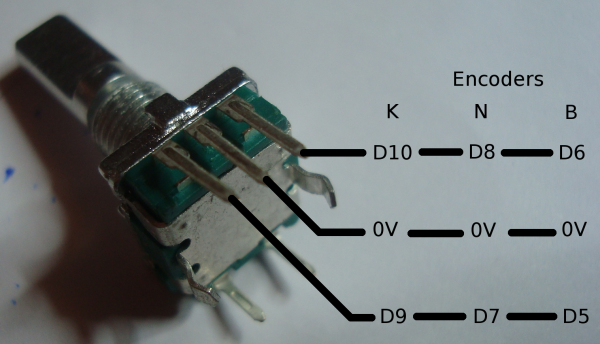
Encoders
The picture encoder.png show how I have solder the wires.
Because if you buy the ebay stuff, there is no sign on it to know which is the ABC.
And the for the two others you can't do mistake.
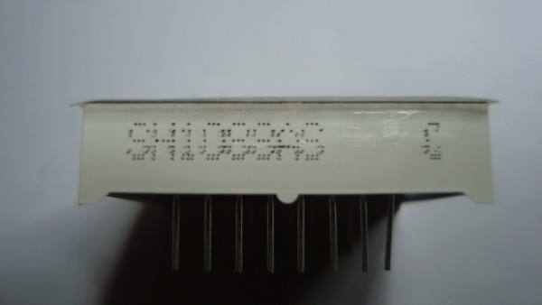
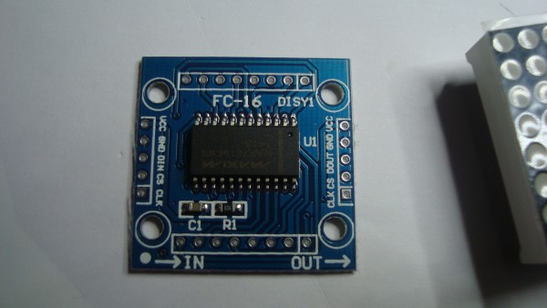
Matrix
As well there is no "good" mark to know the good way to plug it.
There is a reference number on it. picture matrix.jpg
I put this reference next to FC-16 DISY1. At the opposite of IN / OUT
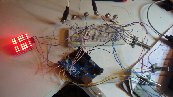
picture board.jpg
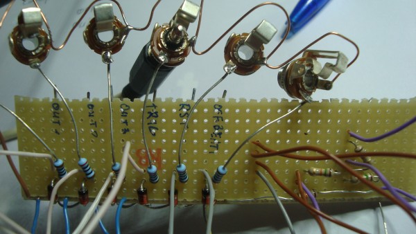
PCB
I don't think a pcb is indispensable.
I did the circuit on a perfboard picture perfboard.jpg
It was just to test, I'll correctly wire this stuff to put on a module.
Upgrade:
It could be good to add a 555 LFO like here :
http://www.555-timer-circuits.com/metronome.html
It allow you to save a LFO on your modular.
And it's possible to plug the LFO with a switch jack, so, without some jack in trig, you use the 555 and when you plug a jack, the 555 is disable.
| Description: |
|
| Filesize: |
1.48 MB |
| Viewed: |
518 Time(s) |
| This image has been reduced to fit the page. Click on it to enlarge. |
|
| Description: |
|
| Filesize: |
701.11 KB |
| Viewed: |
540 Time(s) |
| This image has been reduced to fit the page. Click on it to enlarge. |
|
| Description: |
|
| Filesize: |
789.6 KB |
| Viewed: |
549 Time(s) |
| This image has been reduced to fit the page. Click on it to enlarge. |
|
| Description: |
|
| Filesize: |
831.47 KB |
| Viewed: |
619 Time(s) |
| This image has been reduced to fit the page. Click on it to enlarge. |
|
| Description: |
|

Download (listen) |
| Filename: |
Euclidean.MPG |
| Filesize: |
11.22 MB |
| Downloaded: |
662 Time(s) |
|
|
|
Back to top
|
|
|
sneakthief
Joined: Jul 24, 2006
Posts: 569
Location: Berlin
|
| Posted: Sun May 10, 2015 7:51 am Post subject:
|
|
|
I notice your display is going backwards.
Try my alternate Matrix firmware in the zip archive. It's called LedControl2.
Erase the LedControl folder and rename LedControl2 to LedControl.
_________________
Sneak-Thief - raw electrofunk |
|
|
Back to top
|
|
|
dub halley
Joined: Dec 22, 2010
Posts: 26
Location: Rennes, FRANCE
|
| Posted: Sun May 10, 2015 9:36 am Post subject:
|
|
|
ok, I'll test that when i finished my front panel ...
Everything is unplug .... 
I've got some questions : 
1 - On the schema there are 6 jacks, and on your module there are 10 ??
2 - I'm not sure to understand what the offbeat is ?
Thanks |
|
|
Back to top
|
|
|
sneakthief
Joined: Jul 24, 2006
Posts: 569
Location: Berlin
|
| Posted: Sun May 10, 2015 9:59 am Post subject:
|
|
|
Offbeat: play a beat every on step that trigger #1 does NOT play.
Re. My extra jacks: as I wrote above in the front panel description " Extras: There's a possibility of adding another 4 analog/digital ins for future CV/gate usage. for CV control, I recommend using 2x 1N5819's per CV input. I'll draw a schematic for that later.
...I put A, B, C & D as placeholders for whatever inputs make sense. I decided to set mine to gate inputs for density and length"
_________________
Sneak-Thief - raw electrofunk |
|
|
Back to top
|
|
|
|

 Forum index » DIY Hardware and Software