| Author |
Message |
AlasdairMoons

Joined: Dec 03, 2011
Posts: 105
Location: East-Belgium
|
|
|
Back to top
|
|
 |
AlasdairMoons
Joined: Dec 03, 2011
Posts: 105
Location: East-Belgium
|
|
|
Back to top
|
|
|
wackelpeter
Joined: May 05, 2013
Posts: 461
Location: germany
Audio files: 10
|
 Posted: Wed Aug 12, 2015 9:33 am Post subject: Posted: Wed Aug 12, 2015 9:33 am Post subject:
|
  |
|
why trimpots??? a simple 100k resistor ladder as voltage divider between -15 and + 15 Volts... and between them you select the voltage with your Rotary Switch... okay these must be at least 1% resistors if not better... maybe as sorting out all those 1volt steps would be a lot of octave steps and a very big Rotary Switch... you could Switch between 2 Volt steps... also maybe decrease the resistor after the fine pot to increase it's range if the 1 or 2 Volt steps where not succesfull enough in range...
that's how i think it should work...
_________________
https://soundcloud.com/bastian-j |
|
|
Back to top
|
|
|
AlasdairMoons
Joined: Dec 03, 2011
Posts: 105
Location: East-Belgium
|
|
|
Back to top
|
|
|
wackelpeter
Joined: May 05, 2013
Posts: 461
Location: germany
Audio files: 10
|
| Posted: Wed Aug 12, 2015 12:49 pm Post subject:
|
|
|
well haven't looked at Yves' CV Standard schemo... but maybe it's the same principle...
would suggest that at least one 100K resistor should be between the summing node Input and the voltage from the ladder...
but i think that should work as you're sending a CV to the V/oct Input and the same time the CV from the coarse pot is there... so there should be not much difference if the voltage on the coarse Input is jumping in 1 or 2 Volt steps... the V/oct Input should behave the same... and should be played with an KBD or sequencer too...
_________________
https://soundcloud.com/bastian-j |
|
|
Back to top
|
|
|
bence
Joined: Jan 12, 2013
Posts: 17
Location: Budapest, Hungary
|
| Posted: Tue Aug 25, 2015 7:48 am Post subject:
|
|
|
hi!
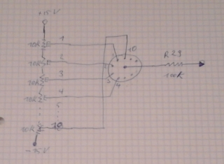
a resistor ladder will work, but try to match them closely. or you can use trimpots, as in the yusynth module. resistor value could be anything from 1k to 100k, but lower is better. you can set the range with extra resistors (trimpots) at the top and bottom of the ladder. so say you need +5 ... -5 octaves, then use a ladder like this: (+15V) - 10k - 10x 1k - 10k - (-15V). then wire each node (11 of them) to the rotary switch and also ground the center node (the one that should be at 0V).
since your supply voltage isn't exact, use trimpots at the ends, so you can trim the top and bottom to exactly +5V and -5V.
still better is to use a pair of voltage regulators, like LM317L / LM337L to make the voltage more stable and independent of any supply ripple and noise.
very important thing: place a simple opamp buffer between the wiper of the rotary switch and the 100k resistor going to the CV summing node.
the reason for this is that the CV summing node is at 0V potential, so the 100k resistor is actually connected parallel to the resistors which are between the switch wiper and ground in the ladder and therefore screwing the precise division. (to put it in a different way: the voltage from the resistor ladder has a high source impedance, which is no good, that's why you need a buffer after the switch).
sorry for the long writing, it was easier for me than drawing a schematic:)
anyway, ask if something is not clear.
offtopic:
that's my cv source, that works the same way: http://imgur.com/a/pmSn9
2 channels of -6 to +5 octaves and 0 to 11 semitones (and other cv stuff)[/url] |
|
|
Back to top
|
|
|
AlasdairMoons
Joined: Dec 03, 2011
Posts: 105
Location: East-Belgium
|
| Posted: Wed Aug 26, 2015 1:14 pm Post subject:
|
|
|
Thanks bence,
I will build a powersupply for the VCOs from a vellemann kit k8042 that already uses the LM317 / LM337 for regulation, could this be enough??
The trimpot idea from yusynth also seems the best solution to me, i will play a bit with the values to see the best results.
The opamp buffer is the TL074 yves uses in his shematics, right?
Piew, that is a bit too deep into electronics to simply rework it for only one input for me
Or could i simpy use a TL072, switchwiper to leg 3 (non inverting in), leg 2 (inverting in) to leg 1 (output) and from there to the 100k R29??
Sorry for those base questions, but I never learned electronics ...
_________________
greetings from belgium, Sascha
my DIY-blog: http://ardvinnamodular.blogspot.be
my DIY Youtube-Channel: https://www.youtube.com/channel/UCWAR64-81C3FbK_Hejz2QHw
my Music-Channel:
https://www.youtube.com/channel/UCzTd_AEK6CVM4gn325wvjYQ
my Facebook:
https://www.facebook.com/AlasdairMoon |
|
|
Back to top
|
|
|
bence
Joined: Jan 12, 2013
Posts: 17
Location: Budapest, Hungary
|
| Posted: Thu Aug 27, 2015 4:39 am Post subject:
|
|
|
if the supply has enough current capability and you don't have many modules or many blinking leds, then it's ok. also, placing a capacitor (like C3) between the supply points is a good idea, as close to the ladder and switch, as possible.
yes, the opamp buffer is like u1a or u1b in yves' schematic.
you can use a tl071 also, because you only need one opamp.
and yes, between switchwiper and R29, like you said.
if the 0-10V (0..+10octave) range is ok for you, then use the same resistor-trimpot ladder (R3, T1-10, R4) as in the yusynth schematic (it's between +15V and GND, not +15 and -15 like in your drawing). but then you will probably need an extra resistor (something around 330k) between -15V and the VCO's CV summing node, to offset the VCO frequency by around -5 octaves, so you can use the whole range of the switch. (remember, using 100k resistors to the summing node the VCO's sensitivity is 1V=1octave /if calibrated properly/, so using a resistor three times bigger to -15V equals -15/3 = -5 octaves. based on this you can calculate the needed offset resistor).
no problem, keep the questions coming:) |
|
|
Back to top
|
|
|
|

 Forum index » DIY Hardware and Software » Thomas Henry designs