Posted: Thu Mar 31, 2016 1:42 pm Post subject:
The Moduletta Subject description: a crossover between Lunettas and modular synths
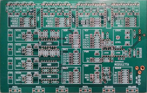
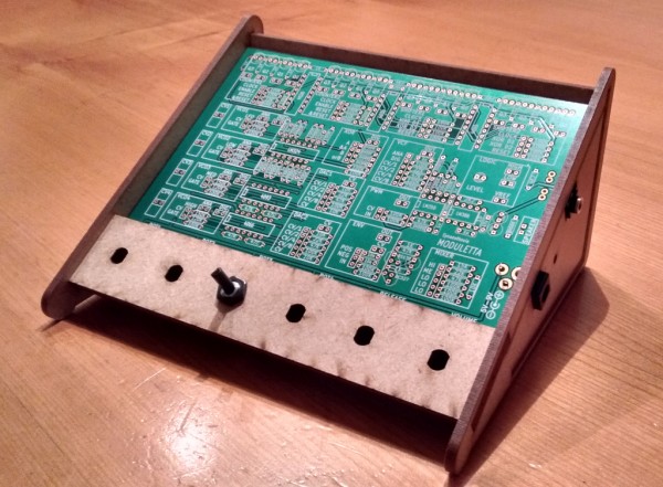
This is the project I am currently working on. I haven't finished the big new Lunetta Lab yet, but decided to build a smaller one first using the triangle VCO and a few other ideas I had recently. It already works fine on breadboard and I wanted to have manufactured PCBs this time. This was a first for me, and of course there were a few small errors. But overall it came out great and I am very happy with the result.
I call this a Moduletta because it is a cross-over between a Lunetta and simple modular synth circuits. The idea was to have a mixture of analog and digital modules that can be patched together via Dupont cables. All analog modules accept control voltages and almost everything can be connected to everything else. The Moduletta is meant to run from a unipolar power supply of 5V to 9V. The chips could stand more, but my current VCO design doesn't work well above 9V.
There will be four pots for control voltages and four VCOs on the board. Two additional pots are hardwired to control the release and the volume. The digital modules include two simple DACs, an XOR/AND/OR gate, two counters, and two shift registers. The analog modules include a PWM, a VCF, a simple envelope generator, and a mixer with amplifier for a builtin speaker. A line output can be used to connect other devices or headphones.
I will post more info as this project continues. The next step is to design a nice case for the Moduletta.
Moduletta PCB.jpg
Description:
Filesize:
1.19 MB
Viewed:
974 Time(s)
This image has been reduced to fit the page. Click on it to enlarge.
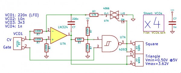
This is the VCO circuit that I am using. I have tested that with several batches of 4093s and unfortunately you have to adjust the resistor network even if the chips are from the same manufacturer and only differ in the date code. The benefit is that you can get an amplitude of 2.8 to 3.1V (at 5V) with that trick. The VCO works fine at 5-9 Volts. At higher voltages, different resistor values are needed again. Instead of the 4066, a FET like the BS170 can be used as well.
Moduletta VCO.JPG
Description:
Filesize:
75.99 KB
Viewed:
906 Time(s)
This image has been reduced to fit the page. Click on it to enlarge.
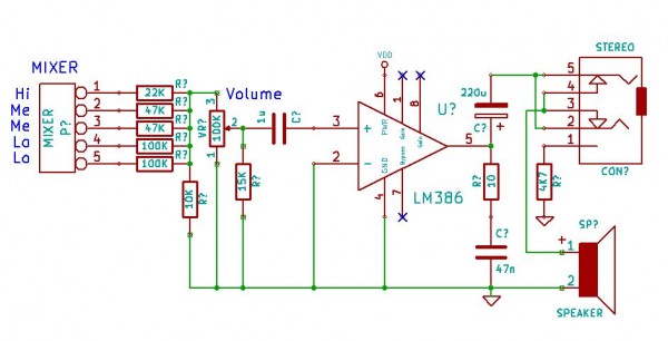
The mixer is a simple resistor network with an LM386 amplifier. The additional 15K resistor makes the response of the linear potentiometer more logarithmic.
This trick is described at http://sound.westhost.com/project01.htm
The line out jack is meant to be used for other devices or headphones, so an additional 4K7 series resistor is added to limit the output volume and save your ears.
Moduletta Mixer.JPG
Description:
Filesize:
63.62 KB
Viewed:
834 Time(s)
This image has been reduced to fit the page. Click on it to enlarge.
Last edited by synaesthesia on Fri Apr 01, 2016 10:17 am; edited 1 time in total
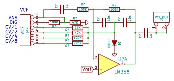
The VCF is a very simple but effective low pass filter design with a bit of resonance, but no self-resonance. The diode current from a control voltage through a resistor network determines the filter response.
This way it is easy to adapt the desired range of the filter response to the available control voltage. Of course another pot could be used here as well. The control voltage used here is typically in a range of 0-3.5 Volts.
There are two signal inputs, one for analog signals (e.g. from the VCOs) and one for stronger digital signals that are scaled down before being fed into the filter.
Mind that this is a unipolar design. Vref is 1.8V here and taken from a red LED. How convenient, this is exactly half of the usable output range for an LM358 at 5 Volts.
Moduletta VCF.JPG
Description:
Filesize:
54.14 KB
Viewed:
828 Time(s)
This image has been reduced to fit the page. Click on it to enlarge.
Last edited by synaesthesia on Fri Apr 01, 2016 10:12 am; edited 1 time in total
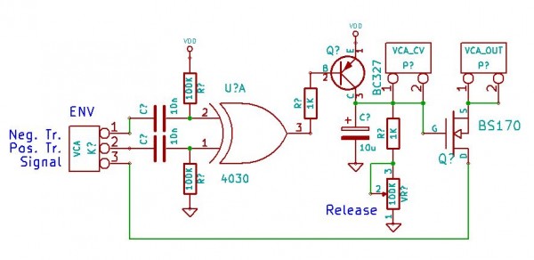
And finally, the envelope generator. I omitted the controls for attack, decay and sustain, and only added a potentiometer for the release time. With the values here you can have a range from short drum-like sounds up to a 2 seconds release time. The envelope curve is taken from the voltage at the 10uF capacitor during discharge.
Two inputs for negative or positive trigger signals are available. They are simply connected via small caps plus pull-up/pull-down resistors, and the internal protection diodes of the CMOS gate handle the rest. The BC327 transistor buffers the output from the CMOS gate and handles the quick charge cycle for the cap.
I have experimented a lot with this circuit and the solution that works best for me is to use the voltage at the cap to control the gate of the FET. The signal is sent straight into the drain of the FET. This works because all other inputs in my circuit are referenced to ground.
Moduletta Envelope.jpg
Description:
Filesize:
53.89 KB
Viewed:
877 Time(s)
This image has been reduced to fit the page. Click on it to enlarge.
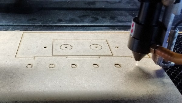
And here is the case for the Moduletta. I visited electrouwe this afternoon and we spent 4 hours on the design for the case (BIG THANKS to Uwe!). We had it right at the second attempt and everything fit together perfectly. The precision of the laser cutter is amazing. The parts were cut from 3mm MDF and they press-fit together and hold even without glue or screws. There will be two addtional parts glued to the sides later and two screws to hold the case together. The speaker sits in the inside with an opening at the back.
Moduletta Laser Cutting.jpg
Description:
The laser cutter at work
Filesize:
243.63 KB
Viewed:
765 Time(s)
This image has been reduced to fit the page. Click on it to enlarge.
Moduletta Case Small.jpg
Description:
The final case without finishing
Filesize:
380.13 KB
Viewed:
815 Time(s)
This image has been reduced to fit the page. Click on it to enlarge.
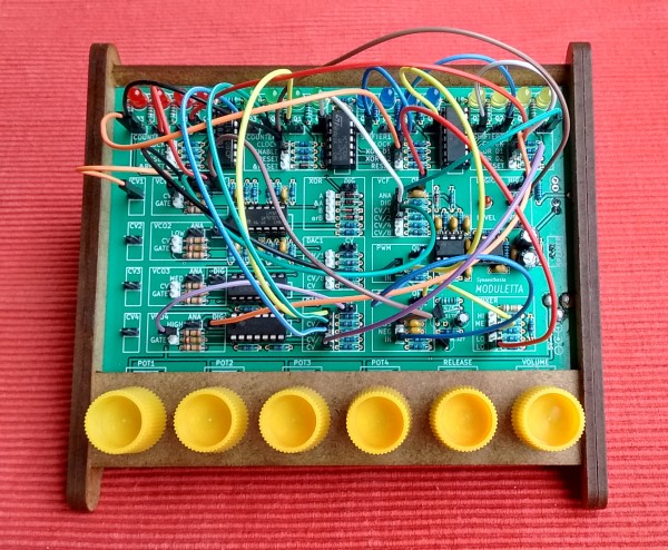
And the finished Moduletta in action playing a brief sample patch. The additional side panels are still missing.
The laser put a nice dark brown finish on the edges of the parts. So I decided to give the MDF parts only a finishing using vegetable oil rather than painting them.
May I ask if (or when) will be available the Moduletta PCB and what will be the price?
I'm trying to use Lunetta systems with my students and this board would certainly be a really functional approach!
Hi 1_over_f_noise, sure. I am planning to use the 20 PCBs I have for a DIY Synth workshop near Stuttgart some time around Mai.
I will post the info once the date is confirmed. If there are some PCBs left after the workshop I can make them available.
This is the finished enclosure with the extra side panels and a recording of a patch. Guess what the potentiometer knobs are made from...
The patch uses two shift registers with XOR feedback controlled by a counter. The high frequency is fed through a VCF. The lower frequency is fed through a PWM and envelope generator. Both are controlled by a triangular wave LFO that also drives the counter. The base frequency VCO is controlled by three counter outputs sent through a DAC.
Moduletta.jpg
Description:
Filesize:
1.14 MB
Viewed:
647 Time(s)
This image has been reduced to fit the page. Click on it to enlarge.
Hi 1_over_f_noise, sure. I am planning to use the 20 PCBs I have for a DIY Synth workshop near Stuttgart some time around Mai.
I will post the info once the date is confirmed.
Good! I suppose that a few of my students could be interested in... I'll will be blocked here due to examinations
synaesthesia wrote:
If there are some PCBs left after the workshop I can make them available.
Well, I hoped it would be possible of purchasing a few of them more rapidly...anyway, I'll try to wait your news after the workshop Last edited by 1_over_f_noise on Sat Apr 09, 2016 9:30 am; edited 1 time in total
That is thoroughly marvellous. The sound file you posted reminds me of the opening titles of TV science shows circa 1981. This is meant as a compliment!
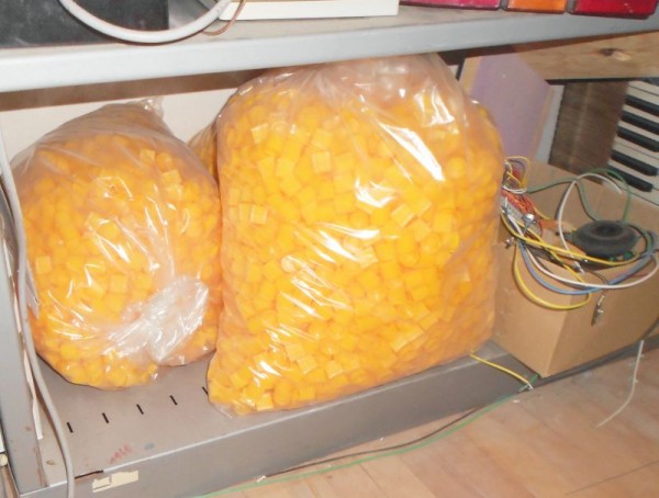
another riddle: guess how long we were collecting "mustard knobs" for
the upcoming Moduletta (Mustardetta?) workshop ;-)
Well ..judging the way they are packed .. they were never used?
Its a great looking device BTW, impressed by that laser cutter work, really nice! _________________ Jan
also .. could someone please turn down the thermostat a bit.
Sorry to be a pain... I can't understand how that circuit works at all. Why doesn't the op-amp integrator just ramp up forever i.e. to saturation and stay there? I can't figure out what causes the triangle wave to ramp down again.
That was what I thought, but I still can't see how it works. When the triangle wave output (i.e. voltage at the lower plate of the capacitor) is high, assuming the gate input is high, the NAND will be low so the 4066 is off.
Even if it weren't, is grounding the other plate of the capacitor going to discharge it? I get terribly confused when trying to figure this stuff out.
... is grounding the other plate of the capacitor going to discharge it?
yes, because GND is always more negative than the integrators reference voltage @ pin 3. In fact pin 3 is kept exactly @ CV/2 so ramping up and ramping down voltage are both |CV/2|. the down ramp R 100k is always connected to CV, so if an up ramp happens, current through the switch must be exactly 2x the downramp current to maintain a symmetrical triangle.
That's why R in series in the switch is 47k.
summarized:
I_down_ramp = (CV - CV/2) / R = CV/2R //R=100k
I_up_ramp = (I_down_ramp - (CV/2)/(R/2)
= CV/2R - CV/R = - CV/2R
=> I_up_ramp = - I_down_ramp => sym. triangle
As luck would have it, I'm reading Horowitz and Hill The Art of Electronics at the moment, in my quest to understand and build some synthesizers, and this circuit was on the very next page when I opened it up this morning. Their explanation gave me some clues but with the addition of yours I am there.
You cannot post new topics in this forum You cannot reply to topics in this forum You cannot edit your posts in this forum You cannot delete your posts in this forum You cannot vote in polls in this forum You cannot attach files in this forum You can download files in this forum

 Forum index » DIY Hardware and Software » Lunettas - circuits inspired by Stanley Lunetta