| Author |
Message |
Cfish

Joined: Feb 24, 2016
Posts: 477
Location: Indiana
|
 Posted: Tue Nov 15, 2016 6:12 pm Post subject: Posted: Tue Nov 15, 2016 6:12 pm Post subject:
|
  |
|
| Can point at a Chinese 3080 that I know is good at about a dollar each American. I actually suspect that the problem is in the schematic. The EFM VCO I showed required greater cap values to get it in to usable audio range. I'm not sure EFM was truly known for testing everything they put out. Think they sold kits then disappeared. |
|
|
Back to top
|
|
 |
alanwilder81
Joined: Sep 03, 2016
Posts: 310
Location: italy
|
|
|
Back to top
|
|
|
alanwilder81
Joined: Sep 03, 2016
Posts: 310
Location: italy
|
| Posted: Tue Nov 15, 2016 6:27 pm Post subject:
|
|
|
it's a good news to hear about a cheap source for our OTAs. Have they proved reliable then? i'd be interested also in other components !  |
|
|
Back to top
|
|
|
Cfish
Joined: Feb 24, 2016
Posts: 477
Location: Indiana
|
| Posted: Tue Nov 15, 2016 6:32 pm Post subject:
|
|
|
| To alanwilder81 I feel like something is missing. Are you sure it's all there? |
|
|
Back to top
|
|
|
PHOBoS

Joined: Jan 14, 2010
Posts: 5973
Location: Moon Base
Audio files: 709
|
| Posted: Tue Nov 15, 2016 6:38 pm Post subject:
|
|
|
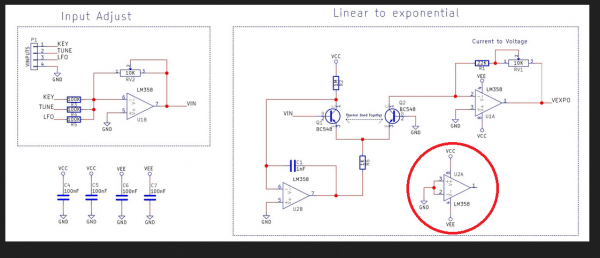
| alanwilder81 wrote: | hey Chris,
i'd like to ask you another question regarding the third op amp used in the VCO schematic,that i circled in red. It's not quite clear to me how its connected.
Seems it has both inverting and non inverting input shorted and tied to ground 
it's confusing me a bit |
That's just a way to 'disable' an unused opamp so it doesn't cause any noise. I usually just connect it as a voltage follower
(inverting input to output) and connect the non-inverting input to GND.
_________________
"My perf, it's full of holes!"
http://phobos.000space.com/
SoundCloud BandCamp MixCloud Stickney Synthyards Captain Collider Twitch YouTube |
|
|
Back to top
|
|
|
Cfish
Joined: Feb 24, 2016
Posts: 477
Location: Indiana
|
| Posted: Tue Nov 15, 2016 6:49 pm Post subject:
|
|
|
Thanks PhoBos
That's what I thought. Was.nice they threw in a diod or 2 to make it look useful. Ugh.
I know EFM sold this as a kit. If you figure out that OTA I would love to know
Have heard some EFM kits had problems. |
|
|
Back to top
|
|
|
alanwilder81
Joined: Sep 03, 2016
Posts: 310
Location: italy
|
|
|
Back to top
|
|
|
alanwilder81
Joined: Sep 03, 2016
Posts: 310
Location: italy
|
| Posted: Tue Nov 15, 2016 6:58 pm Post subject:
|
|
|
anyway,
it's late night here in italy, and really time to go to bed.
A big thanks to both Cfish and Phobos for the prompt support. 
we'll talk tomorrow |
|
|
Back to top
|
|
|
Cfish
Joined: Feb 24, 2016
Posts: 477
Location: Indiana
|
| Posted: Tue Nov 15, 2016 6:59 pm Post subject:
|
|
|
| My personal respons would be, that is a lot of parts for a VCO that isnt temperature compensated and is no more than it is. Almost as many parts as a Thomas HenreynVCO1 without the bang for your buck. |
|
|
Back to top
|
|
|
alanwilder81
Joined: Sep 03, 2016
Posts: 310
Location: italy
|
| Posted: Tue Nov 15, 2016 7:06 pm Post subject:
|
|
|
yes cfish,
it's very high parts count,almost ridicolous compared to other VCOs that are more minimal yet offer some means of temperature compensation.
But i want to get this together just to do a quick and dirty test of the Yves Usson keyboard circuit.
That aside, as soon as i make sure the keyboard is working right,i can disassemble the VCO. It's not meant to be definitve nor to go on my synth whatsoever !!  |
|
|
Back to top
|
|
|
alanwilder81
Joined: Sep 03, 2016
Posts: 310
Location: italy
|
| Posted: Wed Nov 16, 2016 10:36 am Post subject:
|
|
|
hello chaps,
update !
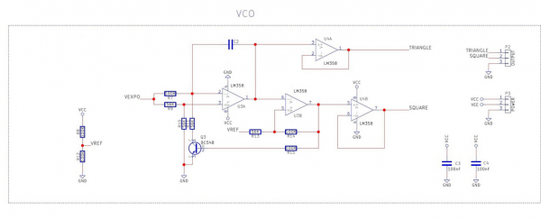
The above VCO works correctly,it outputs a wide triangle and square waves signals over a resonable frequency range. sounds ok.
i employed TL082 in place of the LM358 specified.
The schematics suggests to power the circuit with +- 5 V dual supply,but i wonder if i can power it with the regular +- 12 V i use for all my modules !
it'd save me the bother to hook up another extra supply just for this testing VCO
Cheers ! |
|
|
Back to top
|
|
|
PHOBoS
Joined: Jan 14, 2010
Posts: 5973
Location: Moon Base
Audio files: 709
|
| Posted: Wed Nov 16, 2016 12:17 pm Post subject:
|
|
|
I was going to say it should work fine on -/+ 12V since it doesn't have any reference to the supply (except for that fake GND) but if you use
a dual supply GND becomes V- and it does have the transistor and R10 attached to it. So allthough it will probably work you might have to
adjust some values. There is a way to find out of course 
_________________
"My perf, it's full of holes!"
http://phobos.000space.com/
SoundCloud BandCamp MixCloud Stickney Synthyards Captain Collider Twitch YouTube |
|
|
Back to top
|
|
|
alanwilder81
Joined: Sep 03, 2016
Posts: 310
Location: italy
|
| Posted: Wed Nov 16, 2016 1:54 pm Post subject:
|
|
|
thanks Phobos
great news is that today i was able to test the Yusynth keyboard circuit with the VCO we discussed earlier. Designed to cover 3 octaves, it did an ok job from what i see.I cant wait for others to get the same circuit done and compare the results
As for that simple VCO, another noob question, so please bear with me 
i am already driving the VCO with a dual +-5 V supply,so i dont get the point where you state ""but if you use a dual supply GND becomes V- ""
i wonder why the original design specifies only that low voltage when all synth modules get at least 12 v or more  |
|
|
Back to top
|
|
|
PHOBoS
Joined: Jan 14, 2010
Posts: 5973
Location: Moon Base
Audio files: 709
|
| Posted: Wed Nov 16, 2016 2:01 pm Post subject:
|
|
|
The only place I see a negative voltage is on P3 which I assume is a connector. I don't see it used anywhere in the circuit itself.
So if you would power it with a dual supply you connect V- to what is GND now, and you connect GND to what is Vref now (you can leave
out those resistors). As for the low voltage, I don't know. Maybe a second set of regulators is used to create a more stable isolated supply
just for the VCO.
btw, I am probably more of a noob than you when it comes to VCO's
_________________
"My perf, it's full of holes!"
http://phobos.000space.com/
SoundCloud BandCamp MixCloud Stickney Synthyards Captain Collider Twitch YouTube |
|
|
Back to top
|
|
|
alanwilder81
Joined: Sep 03, 2016
Posts: 310
Location: italy
|
| Posted: Wed Nov 16, 2016 2:12 pm Post subject:
|
|
|
Phobos thanks for all those ideas !i must admit need to get a better understanding of virtual ground, voltage reference and similar concepts that i am still trying to get a grasp with !
i will look further into some theory,as i really, really need it ! |
|
|
Back to top
|
|
|
alanwilder81
Joined: Sep 03, 2016
Posts: 310
Location: italy
|
|
|
Back to top
|
|
|
alanwilder81
Joined: Sep 03, 2016
Posts: 310
Location: italy
|
| Posted: Thu Nov 17, 2016 1:52 pm Post subject:
|
|
|
to Phobos
right now i came across your wonderful ""PHOBoS DIY Synth schematics"", and as i read along, i found the woodworking part of your project.
In there, you mention lacquering and the bother of waiting for every coat to dry.
Well,immodestly i thought I might come in handy with some advices, as i do wood restoration and painting jobs both as a hobby and a for a living.
Water based finishes are the answer, because they are not toxic , dry quickly and generally have little or no residual odor after less than a couple of hours.
I am planning on building my little modular with pine wood painted with those water based varnishes.
Definitely off topic, but hey, might be beneficial to many |
|
|
Back to top
|
|
|
PHOBoS
Joined: Jan 14, 2010
Posts: 5973
Location: Moon Base
Audio files: 709
|
| Posted: Thu Nov 17, 2016 6:02 pm Post subject:
|
|
|
You are absolutely correct about waterbased finishes. The main reason for using the paint I used was because it is what I have.
I originally bought it for another purpose but that never happened and I still have a couple of cans. So to keep it cheap I use that.
For smaller projects I usually use acrylic spraypaint which does dry very fast and it usually makes it possible to finish painting
something in a single day (unless I use multiple colors than I let it harden a bit longer).
and to go more off-topic. For a short while I worked at a place that fixed (wooden) furniture or gave it a new purpuse. But they
also made new furniture for daycare centers and schools that were usually painted in bright colors and for that waterbased paint
was used. So I am familair with the advantage of it, but thanks for mentioning it.
_________________
"My perf, it's full of holes!"
http://phobos.000space.com/
SoundCloud BandCamp MixCloud Stickney Synthyards Captain Collider Twitch YouTube |
|
|
Back to top
|
|
|
alanwilder81
Joined: Sep 03, 2016
Posts: 310
Location: italy
|
| Posted: Fri Nov 18, 2016 6:56 am Post subject:
|
|
|
hello Phobos
it's not off topic.It's never off topic when it come to talking woodworks I dont know whether or not we should open a new thread for cabinets making,lacquering,gluing and stuff, but for the moment i'd be very happy to share with you and other chaps our experiences in this field.
I find myself doing carpentry more as a hobby nowadays,as the crisis in italy has nearly sunk my little business. i too worked in a nice antique furniture restoration shop, when i lived in London. Amazing times then.
I learnt the shit out of those experienced craftsmen who put so much effort and love in restoring furnitures, doors and alikes.
Also, i truly believe that woodworking is an essential skill to develop within synthesizers DIY producing.
I happen to love the wood warmth together with the analog sound warmth itself.The result is bigger than the sum of the single parts!
So soothing to make detuned PWM lines out of a synth with a walnut cabinet !
so, i am totally open to any new ideas,projects, design you might come up with to realize and discusse !
back to electronics, i think my above question regarding the -10 V thing went unnoticed watcha think?
cheers !! |
|
|
Back to top
|
|
|
PHOBoS
Joined: Jan 14, 2010
Posts: 5973
Location: Moon Base
Audio files: 709
|
| Posted: Fri Nov 18, 2016 7:19 am Post subject:
|
|
|
| alanwilder81 wrote: | i think my above question regarding the -10 V thing went unnoticed watcha think?
cheers !! |
that'll work but since you already have a -12V supply it makes more sense to use that. You could make a voltage divider with some resistors to create
a voltage of -10V and than buffer it with an opamp configured as a voltage follower. A better solution would be if instead of just using resistors you
use a zenerdiode or an actual voltage reference like the LM4040CIZ-10.0. You might not even need the opamp if you do this, but you probably don't
have those laying around at the moment.
_________________
"My perf, it's full of holes!"
http://phobos.000space.com/
SoundCloud BandCamp MixCloud Stickney Synthyards Captain Collider Twitch YouTube |
|
|
Back to top
|
|
|
alanwilder81
Joined: Sep 03, 2016
Posts: 310
Location: italy
|
| Posted: Fri Nov 18, 2016 8:00 am Post subject:
|
|
|
thanks Phobos,
no, i dont have that component right now. I plugged that external 10 V supply just for a quick and dirty test, well aware it's rough and far from ideal. 
Now,looking for a definitive solution.I only have LM 317,(positive regulator), but not the LM 337 which will do the job from what i've heard.
I have also a bunch of zener diodes of many values.Which do i pick and how do i connect it?
Fixing this little thing is proving to be more difficult than the actual building of the whole circuit !
thanks ! |
|
|
Back to top
|
|
|
Grumble

Joined: Nov 23, 2015
Posts: 1320
Location: Netherlands
Audio files: 30
|
| Posted: Fri Nov 18, 2016 3:49 pm Post subject:
|
|
|
| alanwilder81 wrote: | back to electronics, i think my above question regarding the -10 V thing went unnoticed watcha think?
cheers !! |
This was already covered on page 4 of this thread   |
|
|
Back to top
|
|
|
alanwilder81
Joined: Sep 03, 2016
Posts: 310
Location: italy
|
| Posted: Fri Nov 18, 2016 3:54 pm Post subject:
|
|
|
grumble,
believe it or not,i haven't got a negative voltage regulator to do the job |
|
|
Back to top
|
|
|
alanwilder81
Joined: Sep 03, 2016
Posts: 310
Location: italy
|
| Posted: Fri Nov 18, 2016 4:00 pm Post subject:
|
|
|
moreover,it seems that there are different methods of achieving that, all quite obscure to a total green horn like me. 
its gonna be a tradeoff. Best efficient solution with the components i have available |
|
|
Back to top
|
|
|
wackelpeter
Joined: May 05, 2013
Posts: 461
Location: germany
Audio files: 10
|
| Posted: Sat Nov 19, 2016 1:43 am Post subject:
|
|
|
| alanwilder81 wrote: | moreover,it seems that there are different methods of achieving that, all quite obscure to a total green horn like me.
its gonna be a tradeoff. Best efficient solution with the components i have available |
Maybe check the schematics of some Buchla (Pulser or Envelope Generator from the Easel) , Serge (VCA) or Ken Stone (triple-bi-directional router) circuits, they show some different methods to achieve the desired result.
For some simple things like this you can use this simulator: http://www.falstad.com/circuit/ to mess around with some values and trying out several things...
But it's not going to help if you think it will help you troubleshoot some more complex circuits like i tried with my Buchla Envelope Generator from the Easel... it's more useful for some basic applications and circuits...
I believe there's still a downloadable version of this somewhere, but you would need Java on your PC.
_________________
https://soundcloud.com/bastian-j |
|
|
Back to top
|
|
|
|

 Forum index » DIY Hardware and Software » The layout factory