| Front Page | Radio | Media | Forum | Wiki | Links |

and electronic music
|
|
Dedicated to
experimental electro-acoustic and electronic music |
|
|
|
The site will be down to cut over to a new server on
|
 Forum index » DIY Hardware and Software Forum index » DIY Hardware and Software |
|
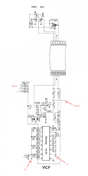
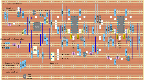
Roland SH101 VCF DIY
|
 
|
Moderators: jksuperstar, Scott Stites, Uncle Krunkus
Page 1 of 1 [13 Posts] |
View unread posts View new posts in the last week Mark the topic unread :: View previous topic :: View next topic |
| Author | Message | |||||||||||||||||||
|---|---|---|---|---|---|---|---|---|---|---|---|---|---|---|---|---|---|---|---|---|
isak
 Joined: Dec 13, 2009 Posts: 847 Location: Israel Audio files: 18 |
|
|||||||||||||||||||
|
|
||||||||||||||||||||
Grumble
 Joined: Nov 23, 2015 Posts: 1320 Location: Netherlands Audio files: 30 |
|
|||||||||||||||||||
|
|
||||||||||||||||||||
|
isak
Joined: Dec 13, 2009 Posts: 847 Location: Israel Audio files: 18 |
|
|||||||||||||||||||
|
|
||||||||||||||||||||
|
alanwilder81
Joined: Sep 03, 2016 Posts: 310 Location: italy |
|
|||||||||||||||||||
|
|
||||||||||||||||||||
|
alanwilder81
Joined: Sep 03, 2016 Posts: 310 Location: italy |
|
|||||||||||||||||||
|
|
||||||||||||||||||||
jbeuckm
 Joined: Nov 30, 2008 Posts: 165 Location: Stockholm Audio files: 9 |
|
|||||||||||||||||||
|
|
||||||||||||||||||||
|
alanwilder81
Joined: Sep 03, 2016 Posts: 310 Location: italy |
|
|||||||||||||||||||
|
|
||||||||||||||||||||
|
wackelpeter
Joined: May 05, 2013 Posts: 461 Location: germany Audio files: 10 |
|
|||||||||||||||||||
|
|
||||||||||||||||||||
|
alanwilder81
Joined: Sep 03, 2016 Posts: 310 Location: italy |
|
|||||||||||||||||||
|
|
||||||||||||||||||||
|
alanwilder81
Joined: Sep 03, 2016 Posts: 310 Location: italy |
|
|||||||||||||||||||
|
|
||||||||||||||||||||
|
wackelpeter
Joined: May 05, 2013 Posts: 461 Location: germany Audio files: 10 |
|
|||||||||||||||||||
|
|
||||||||||||||||||||
|
alanwilder81
Joined: Sep 03, 2016 Posts: 310 Location: italy |
|
|||||||||||||||||||
|
|
||||||||||||||||||||
|
wackelpeter
Joined: May 05, 2013 Posts: 461 Location: germany Audio files: 10 |
|
|||||||||||||||||||
|
|
||||||||||||||||||||
|
|
Moderators: jksuperstar, Scott Stites, Uncle Krunkus
Page 1 of 1 [13 Posts] |
View unread posts View new posts in the last week Mark the topic unread :: View previous topic :: View next topic |
|
Forum index » DIY Hardware and Software |
|
You cannot post new topics in this forum You cannot reply to topics in this forum You cannot edit your posts in this forum You cannot delete your posts in this forum You cannot vote in polls in this forum You cannot attach files in this forum You can download files in this forum |