| Author |
Message |
Project_2501

Joined: Jan 31, 2018
Posts: 68
Location: Los Angeles
|
 Posted: Tue Jul 30, 2019 2:16 pm Post subject:
PT2399 Circuits? Posted: Tue Jul 30, 2019 2:16 pm Post subject:
PT2399 Circuits? |
  |
|
Just came across the pt2399 datasheet.
Has anyone have an circuit/stripboard layout with the pt2399? If not, I'll take my time and make my own for fun. |
|
|
Back to top
|
|
 |
PHOBoS

Joined: Jan 14, 2010
Posts: 5898
Location: Moon Base
Audio files: 709
|
|
|
Back to top
|
|
|
Ayab
Joined: Oct 27, 2015
Posts: 186
Location: London, UK
|
| Posted: Wed Jul 31, 2019 6:00 pm Post subject:
|
|
|
There is also the "Zeitgeist" pt2399 circuit about here somewhere on E-M.
Attached is the Scott Bernardi circuit, a well known one. See some notes from the forum (not mine):
The regulator circuit is separate from the main circuit so jumper from +V to non-reg in and jumper from reg 5V out to direct reg 5V in.
Pin4 on the pt2399 is digital ground and is connected internally to pin3 (analogue gnd) via approx 10 ohm. So no need to connect anything to the 'digital gnd' pad.
Resistor marked free will set the range of your delay pot (use 100k pot), use 25K trimmer so there is no dead space when you turn the pot.
N.B. Silkscreen/wiring plan shows potentiometers represented seen from the bottom view not the top view.
Works on 12V (replace 47k next to purple in front of Mix Pot connections with jumper)
Hope that is useful
| Description: |
|
| Filesize: |
92.45 KB |
| Viewed: |
2757 Time(s) |
| This image has been reduced to fit the page. Click on it to enlarge. |
|
| Description: |
|

Download (listen) |
| Filename: |
ScottBernardi_VCdelay schemo.pdf |
| Filesize: |
198.42 KB |
| Downloaded: |
1059 Time(s) |
| Description: |
|
Download (listen) |
| Filename: |
ScottBernardi_VCdelay_PCB.pdf |
| Filesize: |
537.21 KB |
| Downloaded: |
889 Time(s) |
|
|
|
Back to top
|
|
|
Grumble

Joined: Nov 23, 2015
Posts: 1320
Location: Netherlands
Audio files: 30
|
|
|
Back to top
|
|
|
Project_2501
Joined: Jan 31, 2018
Posts: 68
Location: Los Angeles
|
|
|
Back to top
|
|
|
ceero
Joined: Jul 25, 2019
Posts: 2
Location: Norway
|
|
|
Back to top
|
|
|
efluon
Joined: Jul 20, 2019
Posts: 8
Location: Hamburg
|
|
|
Back to top
|
|
|
Ayab
Joined: Oct 27, 2015
Posts: 186
Location: London, UK
|
| Posted: Mon Aug 05, 2019 3:55 am Post subject:
|
|
|
Joe Beuckman has very generously posted his Eagle version of the Scott Bernardi PT2399 VC Echo on GitHub.
https://github.com/jbeuckm/pt2399_echo
You can download the Eagle software for free then load Joe's PT2399 design, convert it to Gerber files and send it to a pcb making house like OSH Park. There are also panel designs I think.
And there are many other classic module designs for eurorack on Joe's Github. |
|
|
Back to top
|
|
|
cyclic

Joined: Mar 15, 2015
Posts: 95
Location: hobart
|
| Posted: Mon Aug 19, 2019 6:08 pm Post subject:
|
|
|
Actually, i think that pt2399 he has is more or less the standard datasheet pt2399, although he does include the vc version elsewhere on his github which is available elsewhere, but not as eagle files, just the b&w artwork.
But thanks.for linking, he does have some good stuff for me to tinker with, and to do some dual sided etch tests without the work of laying them out fully... |
|
|
Back to top
|
|
|
cyclic
Joined: Mar 15, 2015
Posts: 95
Location: hobart
|
| Posted: Mon Aug 19, 2019 6:20 pm Post subject:
|
|
|
I should have also said I just bodged together a working vc pt2399 with one of the many simple circuits available (probably the same as the el cheapo complete board linked to above) and with fully homerolled diy vactrol control.
Its far from smooth or linear or logarythmic in its vc response, but it does well enough for a cheap board with 2 stripboard daughterboards for each vc input. I used the 'voltage to resistance' schems from http://thesquarewaveparade.com/images/VtoR.jpg
Basically used the most complex one but with just one attenuated input and a trimpot and wired the resitance directly across the feedback and delay pots, so the original pots act as a preset level. I also used the ljn to log pot hack for the inout attenuator as it unsurprisingly seems to give better led drive response. |
|
|
Back to top
|
|
|
Ayab
Joined: Oct 27, 2015
Posts: 186
Location: London, UK
|
| Posted: Wed Dec 11, 2019 7:17 am Post subject:
|
|
|
Hi Cyclic
You are right. I actually meant to link to the PT2399 VC on Joe's github (and yes this one is not the eagle files but for diy etching):
https://github.com/jbeuckm/ScottBernardi-VCdelay-PCB
I have had bad luck with double sided etching - probably because I tried some smt! Was just not forgiving enough on the lining up.
Interesting to know about your PT2399 with diy vactrol control. Cool and the gang! Hope your builds are going well. |
|
|
Back to top
|
|
|
cslammy
Joined: Apr 27, 2018
Posts: 206
Location: USA
Audio files: 1
|
| Posted: Mon Jun 29, 2020 12:37 pm Post subject:
Wet/Dry? |
|
|
Hi there
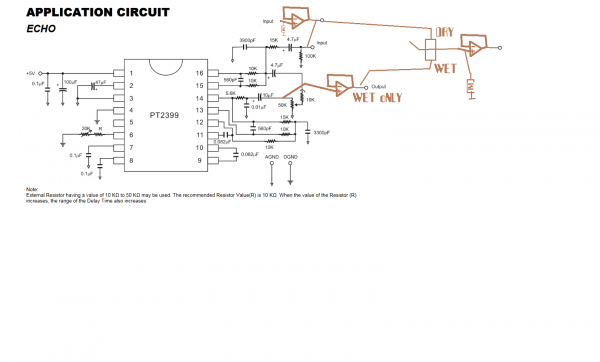
I've built up the PT2399 based on the factory spec sheet as a start.
http://audiodiwhy.blogspot.com/2020/06/pt2399-based-synthesizer-echo-pt-cruiser.html
I am now beginning the process of modding this circuit.
I already have a simple effects send/receive where you put a VCA into the echo loop for CV control of echo (turns out: really easy mod).
Question, I want to add a wet/dry control to a PT2399 design.
I see Befaco has that on their "Crush 3" PT2399 but I can't understand how it works--seems like they use two stages of a 13700 OTA for this, but still, not sure.
How would that work?
I'd want to get rid of the source signal somehow and just end up with the rest of the echo signal (so--what goes back into pin 16, controlled by the feedback pot, only), but I can't see how you can do that w/ the PT2399
Perhaps invert the input and sum it back in to the ECHO signal to only get "everything else BUT input"? (but that would in some cases kill the feedback frequencies as well?)
Does anyone know of a PT2399 design where someone has already figured this out? Maybe something simple I am missing?
Thanks in advance.
_________________
Visit my AUDIODIWHY blog and website |
|
|
Back to top
|
|
|
gabbagabi

Joined: Nov 29, 2008
Posts: 652
Location: Berlin by n8
Audio files: 23
|
|
|
Back to top
|
|
|
cslammy
Joined: Apr 27, 2018
Posts: 206
Location: USA
Audio files: 1
|
| Posted: Tue Jun 30, 2020 7:03 am Post subject:
|
|
|
| gabbagabi wrote: | | the simplest solution that comes to MY mind is attached....you could see how THEY mix together the dry and the wet |
Go GG!
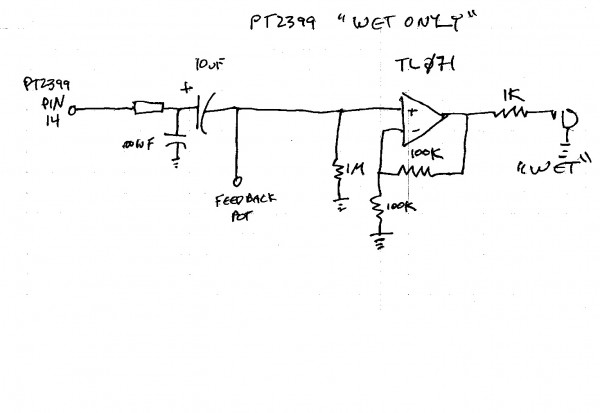
Yeh, I will test again, but the "dry" signal is fully present in the "wet" at that output pin from my tests so far. I'll look again, maybe I got that wrong? I need "wet only", as often as possible 
Back shortly.....
_________________
Visit my AUDIODIWHY blog and website |
|
|
Back to top
|
|
|
gabbagabi
Joined: Nov 29, 2008
Posts: 652
Location: Berlin by n8
Audio files: 23
|
| Posted: Tue Jun 30, 2020 11:34 am Post subject:
|
|
|

the output in the datasheet was on pin 15
i "moved" it to pin 14, the input has no longer direct connection to the output
GL
HF
CU |
|
|
Back to top
|
|
|
cslammy
Joined: Apr 27, 2018
Posts: 206
Location: USA
Audio files: 1
|
| Posted: Tue Jun 30, 2020 12:00 pm Post subject:
|
|
|
| gabbagabi wrote: |
the output in the datasheet was on pin 15
i "moved" it to pin 14, the input has no longer direct connection to the output
GL
HF
CU |
Thanks gabbagabi, I will try scoping PIN 14. If that's "wet only" then we are good....easy solution.
_________________
Visit my AUDIODIWHY blog and website |
|
|
Back to top
|
|
|
gabbagabi
Joined: Nov 29, 2008
Posts: 652
Location: Berlin by n8
Audio files: 23
|
| Posted: Tue Jun 30, 2020 12:11 pm Post subject:
|
|
|
| well, dont scope directly on the pin |
|
|
Back to top
|
|
|
cslammy
Joined: Apr 27, 2018
Posts: 206
Location: USA
Audio files: 1
|
|
|
Back to top
|
|
|
gabbagabi
Joined: Nov 29, 2008
Posts: 652
Location: Berlin by n8
Audio files: 23
|
| Posted: Sun Jul 05, 2020 1:39 pm Post subject:
|
|
|
Glad to hear that it workz mate!
cheers,
gabi |
|
|
Back to top
|
|
|
|

 Forum index » DIY Hardware and Software » The layout factory