| Author |
Message |
dadinfinitum
Joined: Dec 16, 2019
Posts: 41
Location: Maryland, US
|
 Posted: Mon Aug 17, 2020 7:21 pm Post subject:
New to Lunetta with some questions Posted: Mon Aug 17, 2020 7:21 pm Post subject:
New to Lunetta with some questions |
  |
|
Evening,
I've got a bunch of parts and I've been doing a lot of research, but there are a couple things I just can't quite wrap my head around.
Power: is 5V sufficient to power a wide variety of modules? If not, what would be better? Links to any builds would be great (current plan is a basic 9v DC input and 5v for modules).
Output: I'm looking at a passive mixer, but honestly I don't understand how the inputs to it work exactly. If I have an oscillator (say, from a 40106) and I take it's output to another module, do I plug the output from that module to the mixer? Do you have to constantly change what the input of the mixer is if you keep patching to other modules? This is where I can't picture it because I just don't know enough.
Thank you in advance for the help! |
|
|
Back to top
|
|
 |
Steveg

Joined: Apr 23, 2015
Posts: 184
Location: Perth, Australia
|
| Posted: Tue Aug 18, 2020 12:09 am Post subject:
|
|
|
Hi dadinfinitum, Welcome to the Lunetta forum!
Usually bits of the Lunetta (I hesitate to call them modules) are patched together with banana plugs (although there are lots of other options) so the output of your oscillator would be patched across to the mixer which would have a volume control on each input. Something like this works: http://www.all-electric.com/schematic/simp_mix.htm
Logic Noise has a piece on mixers: https://hackaday.com/tag/logic-noise/
So does Castle Rocktronics: http://castlerocktronics.com/modular.html
As for voltage ... 5 volts is about as low as you want to go and about 15 volts is the upper limit (well, maybe 21 volts these days). 5, 9, and 12 volts are popular. If you might want to use TTL chips as well use 5 volts. If you want to make filters and have a bit more headroom to play with and maybe drive an output amp as well go up to 12 volts. 9 volts is a good compromise especially if you want low power battery operation.
You do need to look at the voltage the poster specifies for schematics on this forum. It is usually simple to convert between supply voltages but you will need to change component values for some applications.
There are a bunch of people here who can and will answer questions.
Cheers,
Steveg |
|
|
Back to top
|
|
|
PHOBoS

Joined: Jan 14, 2010
Posts: 5841
Location: Moon Base
Audio files: 709
|
| Posted: Tue Aug 18, 2020 5:08 am Post subject:
|
|
|
One thing to note is that with 5V the output current of CMOS chips decreases a lot.
Not really a problem when driving other chips but it could be if you want to drive LEDs directly.
A mixer is not needed between 'modules' only when you want to sum signals together.
Of course you can also do this with logic chips which is a nice thing with digital signals
but then you generally don't have any level control over the different signals.
for 2 channels you could have a look at the XOA mixer.
or for an output mixer you can have a look here.
If you want to route a signal to multiple 'modules' you need the opposite which would
be a splitter or multiple. With these lunetta synths you can usually get away with a passive
one which can be as easy as just using stackable banana cables. I use bolts and alligator
clips myself which also makes it very easy to do this.
_________________
"My perf, it's full of holes!"
http://phobos.000space.com/
SoundCloud BandCamp MixCloud Stickney Synthyards Captain Collider Twitch YouTube |
|
|
Back to top
|
|
|
dadinfinitum
Joined: Dec 16, 2019
Posts: 41
Location: Maryland, US
|
| Posted: Tue Aug 18, 2020 5:29 am Post subject:
|
|
|
| Steveg wrote: | | As for voltage ... 5 volts is about as low as you want to go and about 15 volts is the upper limit (well, maybe 21 volts these days). 5, 9, and 12 volts are popular. If you might want to use TTL chips as well use 5 volts. If you want to make filters and have a bit more headroom to play with and maybe drive an output amp as well go up to 12 volts. 9 volts is a good compromise especially if you want low power battery operation. |
If I want to use a 9v DC input (be it wall wart or battery), could I use 5v and 9v output to the different parts of the Lunetta? Should I just use a 12v DC wall wart for that?
And what's the best way to get both 5v and 9v? Just two different voltage regulators? Again, very new to this, so I'm unsure how to start a schematic of it. I've followed one that took in 9v and output 5v, but unsure how to get both output. |
|
|
Back to top
|
|
|
JovianPyx

Joined: Nov 20, 2007
Posts: 1988
Location: West Red Spot, Jupiter
Audio files: 224
|
| Posted: Tue Aug 18, 2020 6:47 am Post subject:
|
|
|
It is best to use one power supply voltage to power everything.
With different voltages for different circuits, the outputs from the higher voltage unit can overdrive and even damage the inputs or ESD diodes of lower voltage circuits.
CMOS allows running circuits at a wide range of voltages, from 3 volts to usually around 18 volts. Most circuits will work if you change the power supply voltage. So if you have a few that run at 9v and a few that run at 5v, I'd first try to run them all at 5v. If that doesn't work, try running them all at 9 volts.
Things may work differently with different voltages, but they should still work. Resistors may need adjustment to get things ranged correctly. But in the end, having all circuits on the same PSU is best.
_________________
FPGA, dsPIC and Fatman Synth Stuff
Time flies like a banana.
Fruit flies when you're having fun.
BTW, Do these genes make my ass look fat?
corruptio optimi pessima
|
|
|
Back to top
|
|
|
Steveg
Joined: Apr 23, 2015
Posts: 184
Location: Perth, Australia
|
| Posted: Tue Aug 18, 2020 7:53 pm Post subject:
|
|
|
| I'm with Jovian, unless you already understand the possibilities and pitfalls of multiple voltages then just stick with a single voltage. |
|
|
Back to top
|
|
|
dadinfinitum
Joined: Dec 16, 2019
Posts: 41
Location: Maryland, US
|
| Posted: Wed Aug 19, 2020 3:37 pm Post subject:
|
|
|
| Thanks everyone. I think I'm going to go with 12VAC to +/-9V (essentially the MFOS one). I've got a list going of the different things I want to try and build. I'll eventually start a thread when I start making real progress. |
|
|
Back to top
|
|
|
Steveg
Joined: Apr 23, 2015
Posts: 184
Location: Perth, Australia
|
| Posted: Wed Aug 19, 2020 10:50 pm Post subject:
|
|
|
Hmmm, do you understand that +/- 9volts is not a "single voltage"?
If you are copying MFOS circuits then go with it but almost nothing from this forum will be plug and play compatible. If you don't understand the niceties of split rail vs single rail design you will destroy your CMOS chips.
MFOS is a lo-fi version of a standard synth. It uses a split rail power supply with an analog signal that is symmetrical above and below 0 volts. Its primary signal processing is op-amps.
CMOS chips use a single rail power supply to generate a digital signal that flips between 0 volts and the power supply voltage. At the output end you can process the signal with conventional analogue synth modules but you have to understand the interfacing requirements and once the signal has gone from digital to analogue you can't just feed it back into the digital portions without special processing. Yes, some people do use unbuffered inverters like the 4007 as analog chips but most chips cannot be used that way. |
|
|
Back to top
|
|
|
dadinfinitum
Joined: Dec 16, 2019
Posts: 41
Location: Maryland, US
|
| Posted: Thu Aug 20, 2020 6:55 am Post subject:
|
|
|
I am aware it's not a single voltage. I do have a question then: I see a lot of "modules" that require a + and - voltage, and some that do not. Are these just incompatible with each other? Can you still use single rail "modules" in a split rail system?
Do op amps all require +/- voltage? Are there certain types of "modules" that require op amps? Thinking of things like envelope generators, where most of the ones I've found have +/- voltage in.
Thank you for the question to get me to think more.
Edit: okay, I see that op amps can be single supply, but some might need to be 9v instead of 5v. I guess the simplest thing I can do, then, is make my supply 9v (as long as the bulk of what I want to do can handle that). |
|
|
Back to top
|
|
|
JovianPyx
Joined: Nov 20, 2007
Posts: 1988
Location: West Red Spot, Jupiter
Audio files: 224
|
| Posted: Thu Aug 20, 2020 7:34 am Post subject:
|
|
|
I refer here to dual supply modules:
In fact, cross UPS voltage compatibility is a rather large issue. And people do it rather frequently.
Some modules will work properly.
Some modules will almost work properly.
Some modules will kinda work.
Some modules won't work at all.
While it would be very rare for a module to be destroyed by (for example) increasing from design voltage +/-12 to +/-15, there are bits within those circuits that can cause problems.
If a resistor's job is to control current (using Ohm's Law), then raising or lowering the PSU voltages are likely to change the current - causing an operational problem. This is only one example of the sort of thing you will encounter. This is not something where cut-and-try will be an effective solution finder because the range of circuit oddities will prevent any flowchart or step-by-step instructions that fit all situations.
That said, it's possible someone may have documented such modifications. Possible...
This is where a solid understanding of electronics comes in handy. What you need to know is in books like Horowitz and Hill's "The Art of Electronics". Some modules may use "tricks" (I hate that word) to get something unusual and much of that is described in AofE. And such "tricks" can often depend on the PSU having a specific voltage value. It's not an inexpensive hard bound book, but the PDF version is free and is complete with images.
_________________
FPGA, dsPIC and Fatman Synth Stuff
Time flies like a banana.
Fruit flies when you're having fun.
BTW, Do these genes make my ass look fat?
corruptio optimi pessima
|
|
|
Back to top
|
|
|
Steveg
Joined: Apr 23, 2015
Posts: 184
Location: Perth, Australia
|
| Posted: Thu Aug 20, 2020 6:31 pm Post subject:
|
|
|
Okay, I'm going to have to get technical here and some of the op amp stuff will be stretching my understanding and others may chime in with corrections.
An op amp wants a high and low voltage and a signal that is, on average,half way between the two and not getting too close to either. That half way voltage is the signal ground. Old op amp designs want a low impedance signal ground and two supply rails one above and one below the signal ground. "Single supply" op amps allow the lower voltage to be circuit ground and internally assume the signal ground is exactly half way between the supply voltage and circuit ground. This means the output signal is always offset from circuit ground. There are certain kinds of circuits that are unhappy having a constant DC offset and therefore need DC blocking capacitors inserted in the signal path. This can cause distortion of certain wave forms and if you want precision wave forms for audio effects then this is a bad thing. So most synths are split rail systems. It means also that most circuits are drawn with split rail supplies in mind. So if you have a look at the circuits here: https://sound-au.com/articles/active-filters.htm you will see a components connected to earth. However that is signal earth. To build those circuits using single supply op amps that "earth" has to become half the supply voltage meaning the circuit has to be redrawn in a more complex fashion.
A CMOS chip expects a circuit ground and a supply voltage and (apart from schmitt trigger inputs) always expects the input voltage to be close to ground or the supply voltage. Most people assume that the transition voltage is half the supply voltage and that is often true but, especially on older chips, that might not be the case. CMOS chips have a maximum voltage that used to be 15 or 16 volts but may be up to 21 volts for modern designs. Modern chips also have internal protection diodes to ensure the input voltages do not go above the supply voltage or below the ground voltage but these a intended to deal with stray static charges not mis-connections.
So there are two usual ways you can mix CMOS and op amps. First you can make the low voltage supply rail the "ground" and the high rail the supply voltage but your +/- 9 volts is now an 18 volt supply to the CMOS chips ... better make sure they are modern chips!This is effectively the case for single supply op amps as well.
Or you can make the split rail ground to be the CMOS Ground and the +ve rail the CMOS supply voltage.
In both cases you need DC blocking capacitors to carry the signal from the CMOS part to the op-amp part of the circuit. If you are using single supply op amps all you need are some current limiting resistors and maybe a volume control or mixer.
Now if you have patch cables, as most Lunettas do, suddenly you have a world of pain. You must keep you CMOS outputs and inputs strictly segregated from your split rail inputs and outputs. If you are using single ended op amps you have less problems but you do still need to be aware of the small current supply capabilities of CMOS chips and the strict input voltage limitations.
So, yes it is doable, but you have to understand and plan everything. |
|
|
Back to top
|
|
|
dadinfinitum
Joined: Dec 16, 2019
Posts: 41
Location: Maryland, US
|
| Posted: Thu Aug 20, 2020 6:41 pm Post subject:
|
|
|
| Thank you greatly for the wealth of information. I'm going to stick to a single supply, and I'll be reading a ton. |
|
|
Back to top
|
|
|
Steveg
Joined: Apr 23, 2015
Posts: 184
Location: Perth, Australia
|
| Posted: Thu Aug 20, 2020 11:19 pm Post subject:
|
|
|
There is a heap of stuff you can do without any op amps at all. These pages have loads of circuits. Most Lunettas only use op amps for the mixer and output stages (which may include filters and other effects after the mixer).
Tell us what you are thinking of and we can point you at suggestions. Will you have a keyboard or other input devices? Do you like drones? Harsh noise or melodic? Chiptunes?
Have a look through the Logic Tunes videos. Check out CHRISKELLY's video of his machine. Look at synathesia's moduletta, he posted a lot of circuits earlier. Have a look at Chris Beckstrom's "modular" https://chrisbeckstrom.com/main/the-modular
Enjoy! If you get stuck we're here to help. |
|
|
Back to top
|
|
|
dadinfinitum
Joined: Dec 16, 2019
Posts: 41
Location: Maryland, US
|
| Posted: Fri Aug 21, 2020 12:05 pm Post subject:
|
|
|
| I do have a quick question: if I go the bolts and crocks method of patching (as Phobos does), what do you use to wire from the bolt to the circuit? |
|
|
Back to top
|
|
|
PHOBoS
Joined: Jan 14, 2010
Posts: 5841
Location: Moon Base
Audio files: 709
|
|
|
Back to top
|
|
|
dadinfinitum
Joined: Dec 16, 2019
Posts: 41
Location: Maryland, US
|
| Posted: Fri Aug 21, 2020 2:04 pm Post subject:
|
|
|
| Thank you greatly! Found 100x solder terminal lugs on eBay for a good price. |
|
|
Back to top
|
|
|
dadinfinitum
Joined: Dec 16, 2019
Posts: 41
Location: Maryland, US
|
| Posted: Fri Aug 21, 2020 3:23 pm Post subject:
|
|
|
| Sigh. Another (probably obvious) question: is there a specific type of bolt needed? Or would a zinc plated steel bolt work perfectly fine? Feels like that should be fine. |
|
|
Back to top
|
|
|
PHOBoS
Joined: Jan 14, 2010
Posts: 5841
Location: Moon Base
Audio files: 709
|
|
|
Back to top
|
|
|
dadinfinitum
Joined: Dec 16, 2019
Posts: 41
Location: Maryland, US
|
| Posted: Sun Aug 23, 2020 1:59 pm Post subject:
|
|
|
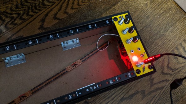
I've wired up a voltage regulator (12v to 9v) for my power, and got an op amp mixer successfully wired on a breadboard. Going to actually build my case tomorrow.
If I'm going to go the alligator clip route, what wire would be ideal to use? Something flexible and comes on a spool would be ideal, yeah? |
|
|
Back to top
|
|
|
PHOBoS
Joined: Jan 14, 2010
Posts: 5841
Location: Moon Base
Audio files: 709
|
| Posted: Mon Aug 24, 2020 4:04 am Post subject:
|
|
|
I just use the ready made ones like these, but the quality of what you get varies a bit. I have some older ones where the insulation
on the croc clips got very hard and makes them almost useless. I have some with very flexible leads and some that are more rigid.
Also the actual copper wire inside can be pretty thin, it's actually mostly insulation but this can vary too. The wires themselves are
actually crimped on to the alligator clips, although you can hardly call it that. It generally holds up but I've had some with bad connections
or broken wires which I soldered and secured with some heatshrink. So if you get them ready made it might not be a bad idea to that
right away.
Having said all that, making your own would give you better quality and you can make them in different lenghts but it will probably
cost you a fair bit more. The clips themselves are less easy to get in different colors, though I guess that's not really that important
and quality varies. Getting some nice flexible wire might be harder. The advantage of the wire used on the ready made ones is that
because the insulation is fairly thick they don't get tangled up very easily but they are still flexible. Silicone wire, which is often used
for professional test leads, would be ideal but it's generally not cheap. Electrically speaking pretty much any wire will do of course.
_________________
"My perf, it's full of holes!"
http://phobos.000space.com/
SoundCloud BandCamp MixCloud Stickney Synthyards Captain Collider Twitch YouTube |
|
|
Back to top
|
|
|
dadinfinitum
Joined: Dec 16, 2019
Posts: 41
Location: Maryland, US
|
|
|
Back to top
|
|
|
Steveg
Joined: Apr 23, 2015
Posts: 184
Location: Perth, Australia
|
| Posted: Sun Aug 30, 2020 2:56 am Post subject:
|
|
|
| Good one! |
|
|
Back to top
|
|
|
Banjo
Joined: Sep 27, 2009
Posts: 89
Location: Lawrence County, Mo. USA
Audio files: 2
|
| Posted: Sun Aug 30, 2020 9:40 pm Post subject:
|
|
|
| Hi dadinfinitum, nice start on your project! I wish I had the patience to make my builds so neat and clean. Keep building! |
|
|
Back to top
|
|
|
PHOBoS
Joined: Jan 14, 2010
Posts: 5841
Location: Moon Base
Audio files: 709
|
|
|
Back to top
|
|
|
dadinfinitum
Joined: Dec 16, 2019
Posts: 41
Location: Maryland, US
|
| Posted: Mon Aug 31, 2020 6:59 am Post subject:
|
|
|
| PHOBoS wrote: | That looks great! 
Those bolts seem a bit massive though, I use M3 myself. |
They are a bit large, but they fit the solder lugs I was able to find at a good price. Alligator clips still fit on them, which might just mean "good enough" haha. |
|
|
Back to top
|
|
|
|

 Forum index » DIY Hardware and Software » Lunettas - circuits inspired by Stanley Lunetta