| Author |
Message |
drgwon
Joined: Nov 18, 2020
Posts: 11
Location: ibiza SPAIN
|
 Posted: Wed Nov 18, 2020 5:56 pm Post subject:
EVIL MOON Posted: Wed Nov 18, 2020 5:56 pm Post subject:
EVIL MOON
Subject description: help me pointing errors on my first intent on lunetta base "synth" |
  |
|
HELLO! This is my first post and also my first intent on design of a lunetta synth.
I been digging for a while in this forum (its amazing how much info is here!! tranks) and learning everything my limited brain has let me. little by little i start understanding how CMOS CHIPS work but still have a lot to learn!!
RECENTLY, encouraged by a friend, i decided to finally put together a noise machine i can use to start my lunetta modular system.
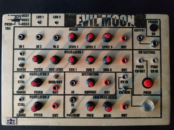
its just a little box with 3 oscillator , a mixer, a distortion and a low pass filter.
i just like to share my schematics with all you so you can point on my errors ( i think there will be a few) or maybe you get some inspiration and you can use part of it for your own creations.
There are a few thing to fix:
1- Levels (the mixer outputs lower level than the filter or the distortion module)
2-Filter distorts if i plug the 3 oscillators on the input, if i plug it thru the mixer i cant not turn up the level of the knobs more than 30% with the 3 oscillator on it (i guess the signal is to hot  ) )
I EDIT POINT 3!!!
3-connecting oscillators 2 or 3 direct to the master out makes the oscillators STOP oscillating.
4- I COULDN´T DETECT THE REASON BUT IC 4069 SUDDENLY STOP WORKING AND I HAD TO REEMPLACE IT. 
5 (this one its the more annoying and mysterious issue cause it was working great at the breadboard) the LDRs on the filter are reducing the volumen drastically and require a lot of light to open the filter,,,vactrol are working but not the external LDRs. im not very happy with the behaviour on the vactrol either its imposible to fully open the filter(maybe i should add a voltaje divider to use it has offset for the vactrol.. im not really sure about it)
WELL I KNOW THAT IS A LOT OF ASKING FOR MY FIRST POST BUT I THINK ITS BETTER TO ASK EVERYTHING AT ONCE.
Last edited by drgwon on Sat Nov 21, 2020 10:18 am; edited 3 times in total |
|
|
Back to top
|
|
 |
dk
Joined: Feb 12, 2019
Posts: 115
Location: Europe
|
| Posted: Thu Nov 19, 2020 1:26 pm Post subject:
|
|
|
Hi and welcome!
It seems your schematics didn't manage to upload? It'll be much easier to address this stuff with those...
_________________
Horrors Of Dial-Up! on Facebook
Horrors Of Dial-Up! on Instagram |
|
|
Back to top
|
|
|
drgwon
Joined: Nov 18, 2020
Posts: 11
Location: ibiza SPAIN
|
|
|
Back to top
|
|
|
Steveg

Joined: Apr 23, 2015
Posts: 184
Location: Perth, Australia
|
| Posted: Fri Nov 20, 2020 4:33 pm Post subject:
|
|
|
Welcome drgwon,
Questions 2 and 4 are probably related ... if you push the mixer volumes too high then the voltage at pin 1 of the 4069 could exceed 9v or be less than 0v. Either way you could destroy the 4069. The presence of R15 helps but I can't tell if it helps enough. I suggest using an op-amp or a bipolar transistor for the mixer would be more robust.
Pins 10 and 12 on the 40106 U6 have no current limiting resistors. Depending on what your master out is connected to it is possible you could have problems when you connect them. The 40106 can only supply very limited current.
There is no biasing on pins 9 and 11 of the 4069 so it is possible your filter circuit has a hard time rising above the on threshold of the 4069. Maybe try making R18 & R19 100K or 1M resistors because you may be getting a significant voltage divider back to the filter input. Just FYI the response curve of the 4069 is very non-linear. The output drops to about 3/4 VCC when the input is just less than 1/2 VCC and then drops to about 1/4 VCC over maybe a volt or less. |
|
|
Back to top
|
|
|
drgwon
Joined: Nov 18, 2020
Posts: 11
Location: ibiza SPAIN
|
|
|
Back to top
|
|
|
Steveg
Joined: Apr 23, 2015
Posts: 184
Location: Perth, Australia
|
| Posted: Sat Nov 21, 2020 3:56 pm Post subject:
|
|
|
If you are avoiding op-amps figure 5 here: https://sound-au.com/articles/audio-mixing.htm is a 1 transistor mixer.
Fair warning, all my CMOS experience is with digital circuits ... my audio experience is limited. So I look at the transfer curves for the 4069 and think that looks like it needs biasing because if the input doesn't get to near 1/2 VCC there is going to be bugger all output signal but that doesn't give me any insight into the best way of achieving that. The two ways that suggest themselves are use a voltage divide with couple of 1M resistors or put a 1M resistor from output to input to self bias the circuit. BUT ... when you do that you risk creating an ultrasonic oscillator if there is any capacitance on the input line and MOS/CMOS transistors have capacitance on the gate as a function of their construction. Maybe someone else here can help with this bit?
you can calculate the resistor size from the 40106 data sheet. From the data sheet the maximum dissipation is 100mW per output transistor which is 0.1W ... you have a power supply of 5V so the maximum current is 0.1/5 = 0.02A. With a 5V supply you need a resistance of at least 5/0.02 = 250 Ohms. You don't want to go anywhere max dissipation because the power handling is far less if the chip goes over 100C. I would be using at least a 2.2K resistor, your suggestion of 4.6K will be fine.
By the way, I can't see any reason why you would need a separate 5V supply for some chips. It will be far simpler to run everything off of 9V. Those chips can handle up to 20V VCC. |
|
|
Back to top
|
|
|
drgwon
Joined: Nov 18, 2020
Posts: 11
Location: ibiza SPAIN
|
| Posted: Sat Nov 21, 2020 6:22 pm Post subject:
|
|
|
Very interesting that 1 transistor mixer!!. Im gonna breadboard it and see how does it responde. it seems that maybe i could simplify it to make a only 1 channel mixer (if that have any sense) and use it as the output stage that im needing. (the op amp mixer also seems quite simple... im not definitely avoiding op amps but as i have the 4069 filter already "working" and as half of the chip was unused, i thought about taking advantage of it and that way build the "synth" with the least possible components,,, with that said i prefer to add more components and have a "synth" that works well than a minimum component broken "synth"  ) )
About BIAS adding a pair of voltage dividers with 1M resistors would not be a difficult solution BUT i wonder if the 100k resonance potentiometer + R21 are doing the function of the 1M resistor that you mentioned adding between the filter´s input and output.
The main reason why im using 9v and 5v its cause the signal was way to hot for my mixer and filter (they add quite distortion to the signal) if i use 9v for the oscillator and the more annoying thing is that it bleeds through ground. After trying different solutions using 5v reduced the bleeding an seems the easier one to me.
Well! im afraid that some things you say are passing way over my head like capacitance and ultrasonic oscillations (the fool inside my head says if they are ULTRASONIC i can hear it and if i cant hear it IT do not really matter ),but they are good to know...even though i dont fully understand i know they are important things to consider.
THANKS AGAIN TO TAKE THE TIME TO ANSWER MY ROOKIE QUESTIONS. |
|
|
Back to top
|
|
|
blue hell
Site Admin

Joined: Apr 03, 2004
Posts: 24474
Location: The Netherlands, Enschede
Audio files: 297
G2 patch files: 320
|
| Posted: Sat Nov 21, 2020 6:26 pm Post subject:
|
|
|
| Steveg wrote: | | Maybe someone else here can help with this bit? |
A Miller cap I'd think .. that is a capacitor from output to input (in parallel to the feedback resistor) which will make the amplifier slower, as in that it will reduce amplification for higher frequencies. This is used in opamp (from out to - in) and transistor (from C to B) circuits as well. So .. pretty much 'standard'.
But then again, when the gate used has no hysteresis there prolly will not be a great risk of oscillation. It depends on the actual phase angle for higher frequencies, selected amplification and the HF characteristics of the gate used .. I forgot the details there .. but can't recall that I ever saw a Miller cap in such a configuration (for CMOS ports that is).
I'd prefer self balancing, as there will be spread on the 'mid point' from device to device. And then use a capaitor to get the signal in, so AC coupling there.
Otoh ... allowing for an off-midpoint trim might make some nice distortion .. but that can just be added with a pot and a resistor ...
_________________
Jan
also .. could someone please turn down the thermostat a bit.
 |
|
|
Back to top
|
|
|
drgwon
Joined: Nov 18, 2020
Posts: 11
Location: ibiza SPAIN
|
| Posted: Sun Nov 22, 2020 10:03 am Post subject:
|
|
|
Ok. Let me recapitulate. Let's see if in not to lost.
__The idea it's to make the signal oscillate around the 1/2 VCC. So the easiest way it's to at bias by a voltage divider before pins 9 and 11 (I assume I have to add BIAS before the mixer "module" to...am I right?).
__it needs a decoupling Capacitor just before pin 9.Right? |
|
|
Back to top
|
|
|
Steveg
Joined: Apr 23, 2015
Posts: 184
Location: Perth, Australia
|
| Posted: Sun Nov 22, 2020 8:32 pm Post subject:
|
|
|
I did some looking around and I think you want the "4069 State Variable Filter" from the diagram on the 4th post on this page: https://electro-music.com/forum/post-439293.html.
It is a self biased design with the long feedback loop making sure the whole filter stays in a useful operating range. Where the dual 100k pots marked cutoff are you will have your assemblage of switched LDRs and pots.
If you are having trouble with the input level being too high you could put a 10K or 100K volume pot from the input to ground and take the input to the resonance pot from the wiper of the volume pot. But I think the resonance pot will achieve this on its own. To make this work with the oscillator outputs you will either need to remove the diodes or add a bleed resistor to ground otherwise the input blocking capacitor will charge up and be unable to discharge.
The main differences from your design are the full end to end biasing / feedback and the blocking capacitor on the input.
FYI even though you cant hear ultrasonic oscillation it is bad because it makes your chips run hot and can swamp the signal you do want to amplify. |
|
|
Back to top
|
|
|
drgwon
Joined: Nov 18, 2020
Posts: 11
Location: ibiza SPAIN
|
|
|
Back to top
|
|
|
drgwon
Joined: Nov 18, 2020
Posts: 11
Location: ibiza SPAIN
|
| Posted: Mon Nov 23, 2020 10:40 am Post subject:
|
|
|
| Steveg wrote: |
If you are having trouble with the input level being too high you could put a 10K or 100K volume pot from the input to ground and take the input to the resonance pot from the wiper of the volume pot. But I think the resonance pot will achieve this on its own. To make this work with the oscillator outputs you will either need to remove the diodes or add a bleed resistor to ground otherwise the input blocking capacitor will charge up and be unable to discharge.
. |
i was thinking about adding a 4.7K current limiting resistor (as you suggest me and another 4.7k to ground just before the oscillator output, that way i divide by two the voltage so its 2.5V for each oscillator and if i mix all together still less than 9v (is that supposition right? or am i not seen something obvious there?).
i dont have any trouble removing the diode now cause i have the 4.7k on the outputs.
i suppose than with the level of the oscillators at 2.5V my 4069 is save and it will not die again.
thanks again!! you are being a GREAT help for me! |
|
|
Back to top
|
|
|
Steveg
Joined: Apr 23, 2015
Posts: 184
Location: Perth, Australia
|
| Posted: Mon Nov 23, 2020 11:52 pm Post subject:
|
|
|
Somehow I missed the second posting of the circuit with the resonance pot included. So that original circuit was okay then when the input isn't overloaded. C4 in your upgraded circuit adds some cancellation of high frequencies (remember ultrasonic oscillation?) it is 100 pF so .0001 uF. Note the values in the other schematic are mF which is 1000 uF but I think a 1000 UF coupling capacitor is way overkill.
I think the resonance pot controlled the feedback by controlling the input levels. I've seen other 4069 circuits doing it like your circuit so you should be good. If the filter is still being overloaded then you can use a volume pot on the filter input as I described earlier.
Your protection of the mixer will probably work but you are hampering your ability to do logic things with the oscillator outputs in the future. If that is not a problem then that is also all good.
Have a look at PHOBoS' post on this page: https://electro-music.com/forum/topic-72084-25.html see the CMOS input protection circuits? Put the middle one between the mixer capacitors and pin 1 of the 4069. If your volume dials are set low enough the everything is good but if they get set too high the diodes will clip the input which should protect the 4069.
With the mixer protected and a volume control on the input to the filter you could ditch the 5V and run everything on 9V. |
|
|
Back to top
|
|
|
drgwon
Joined: Nov 18, 2020
Posts: 11
Location: ibiza SPAIN
|
| Posted: Tue Nov 24, 2020 11:02 am Post subject:
|
|
|
Nice and easy diode protection,It Looks Great!
Is the limits off this diode based protector set by the positive voltage added to the diode on the top on the schematic?
Am I right to suppose than the "analogue" output of the mixer it's going to be OK untill I go over the positive voltage on the "diode protection"? If that is the case I think I'm going to add voltage divider on the oscillators outputs just to have more... headroom? (not sure if that is the right English way to say it )
About the filter modifications: C4 is set in parallel with a 3.3k.. does the resistor affect to the frequency ? In the Original schematic from "YouCantIgnoreMyTecno" his resistor is 100k(I know its a different configurations but I guess the Capacitor and the resistor in parallel are interacting together in a way I don't understand)
The main reason I'm using 5v is because I had an horrible bleeding of the oscillator.. when the pots on the mixer are all the way down I can still hear the oscillator doing their thing.
It was the simplest way I found to solve the problem. (Before that I was trying to add Capacitors near the chips and between ground and positive rail on the power supply..with not much luck. Every chip has his own independent ground path and the tipical capacitor between positive and ground to make it a more stable)
Last edited by drgwon on Tue Nov 24, 2020 7:47 pm; edited 2 times in total |
|
|
Back to top
|
|
|
drgwon
Joined: Nov 18, 2020
Posts: 11
Location: ibiza SPAIN
|
| Posted: Tue Nov 24, 2020 12:02 pm Post subject:
|
|
|
| Steveg wrote: |
Your protection of the mixer will probably work but you are hampering your ability to do logic things with the oscillator outputs in the future. If that is not a problem then that is also all good.
|
Ok. I did not though about that. Mmmmm. I gonna have to think I little more about voltage divider on the oscillator outputs.
EDIT:i think the way to go is use 9v for all the chips (i gonna have to spend more time trying to fix the oscillators bleeding).. Im not going to use voltage dividers at the oscillators outputs(the plan for this its to have a "stand alone" little noisy box which i can use with a Lunetta modular in the future) But then i still have to find a way to win some headroom for the 4069. the diode protection seems a nice thing to do for keeping the 4069 save but it will clip the signal really hard if the limit is 9v and i connect three 9v oscillators (9v x 3 =27v)... maybe the voltage divider can be at the mixer and filter inputs OR IS THERE A MORE EASY/CONVENIENT WAY TO DO THIS?
Last edited by drgwon on Tue Nov 24, 2020 8:10 pm; edited 1 time in total |
|
|
Back to top
|
|
|
drgwon
Joined: Nov 18, 2020
Posts: 11
Location: ibiza SPAIN
|
| Posted: Tue Nov 24, 2020 1:51 pm Post subject:
|
|
|
Another thing I trying to calculate is if I'm asking to much to our little friend 4069. Temperature can be a issue if I use this chip has linear amplifier.
Digging in the web i found this:
If you tried to use all 6 inverters in a 4069UB as amplifiers at 15V, the chip would be dissipating well over one watt, and would overheat and eventually die. The Texas data sheet suggest you can dissipate up to 500mW in the whole chip, but I would never do that to a CMOS chip. I would stick within 100-200mW tops. If the chip gets too hot the input leakage currents are likely to increase, and upset the DC stability.
I Don't really know how to calculate how much I'm pushing the 4069. |
|
|
Back to top
|
|
|
drgwon
Joined: Nov 18, 2020
Posts: 11
Location: ibiza SPAIN
|
|
|
Back to top
|
|
|
|

 Forum index » DIY Hardware and Software » Lunettas - circuits inspired by Stanley Lunetta