| Author |
Message |
urbanscallywag

Joined: Nov 30, 2007
Posts: 317
Location: sometimes
|
 Posted: Fri Oct 10, 2008 11:10 am Post subject: Posted: Fri Oct 10, 2008 11:10 am Post subject:
|
  |
|
Ah, sounds interesting.
I was imagining making a stripped down FS1A and patching in modules to do mixing and switching like that but I seem to have underestimated a stand alone unit (which also makes sense from a power point of view). |
|
|
Back to top
|
|
 |
urbanscallywag
Joined: Nov 30, 2007
Posts: 317
Location: sometimes
|
| Posted: Tue Oct 21, 2008 6:57 pm Post subject:
|
|
|
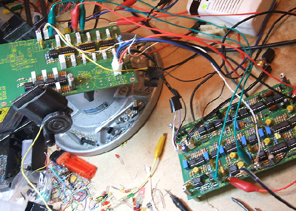
My FS1A is almost entirely populated! I'm waiting on tempcos that will probably be here by the time I finish wiring the FS1A, and I left regulators out so I can run it on the bench before putting it into an enclosure. I need to get a flux pen to do the surface mount capacitors too.
Some building tips:
Mind the resistors near the connectors, try to mount them pushed away from the connector. I am using MTA100 headers and I had to push the resistors over a bit.
In the dome filter mount the resistors before the resistor arrays or else it might be a bit of a squeeze for your iron. I would do the resistors, then the arrays, then the IC sockets (optional), then the (apparently heat sensitive) polystyrene capacitors.
Make sure you buy narrow/tall 22uF capacitors if available. Mine are fat/short and they are a little bit of a tight squeeze when mounted next to each other.
Pay attention (as mentioned on the BOM) to the single versus multi-turn pot footprints. Specifically you cannot use single turn with the inline pin out (oops).
JH's FS1A is very well documented. I like the actual component values on the PCB, it saves a lot of work/time. I hope the calibration goes as smoothly.
On to cables and calibration!  |
|
|
Back to top
|
|
|
toppobrillo

Joined: Dec 10, 2005
Posts: 766
Location: oakland, ca
G2 patch files: 1
|
|
|
Back to top
|
|
|
urbanscallywag
Joined: Nov 30, 2007
Posts: 317
Location: sometimes
|
| Posted: Sat Nov 08, 2008 11:07 am Post subject:
|
|
|
Cool. That's a nice Panavise you've got there. 
I just have to wire the switches. Wish I had time.  |
|
|
Back to top
|
|
|
toppobrillo
Joined: Dec 10, 2005
Posts: 766
Location: oakland, ca
G2 patch files: 1
|
|
|
Back to top
|
|
|
urbanscallywag
Joined: Nov 30, 2007
Posts: 317
Location: sometimes
|
| Posted: Sun Nov 09, 2008 5:28 pm Post subject:
|
|
|
Wow, you've got the Serge thing down.
What is the signal on the VCO jack? |
|
|
Back to top
|
|
|
toppobrillo
Joined: Dec 10, 2005
Posts: 766
Location: oakland, ca
G2 patch files: 1
|
| Posted: Sun Nov 09, 2008 9:43 pm Post subject:
|
|
|
| hey, yeah i think i do ... um the 0 and 90 are the quadrature vco outputs. jurgen has a direction input on his FS-1, i thought that was a cool idea, to switch it electronically, so once i get it wired up better i may try and add that functionality to mine since i have an extra space. |
|
|
Back to top
|
|
|
urbanscallywag
Joined: Nov 30, 2007
Posts: 317
Location: sometimes
|
| Posted: Sun Nov 09, 2008 10:11 pm Post subject:
|
|
|
| I understand the 0 and 90 degree outputs, but what's the purple jack for? |
|
|
Back to top
|
|
|
Luka

Joined: Jun 29, 2007
Posts: 1003
Location: Melb.
|
|
|
Back to top
|
|
|
jhaible

Joined: May 25, 2007
Posts: 2014
Location: Germany
Audio files: 24
|
| Posted: Mon Nov 10, 2008 2:47 pm Post subject:
|
|
|
| urbanscallywag wrote: | Wow, you've got the Serge thing down.
What is the signal on the VCO jack? |
Love the look of this Serge panel, and it gives me a very special feeling to see one of my circuits in that format:
The Serge catalogue with its module descriptions was a main source of inspiration for me when I started to design my own JH-3 synthesizer.
JH.
_________________
"I tell you the truth, if anyone says to this mountain, 'Go, throw yourself into the sea,' and does not doubt in his heart but believes that what he says will happen, it will be done for him. Therefore I tell you, whatever you ask for in prayer, believe that you have received it, and it will be yours." (Mk 11,23f) |
|
|
Back to top
|
|
|
toppobrillo
Joined: Dec 10, 2005
Posts: 766
Location: oakland, ca
G2 patch files: 1
|
| Posted: Mon Nov 10, 2008 5:10 pm Post subject:
|
|
|
| Quote: | | I understand the 0 and 90 degree outputs, but what's the purple jack for? |
the 'direction' input i was talking about below, assuming i get it to work
| Quote: | | Love the look of this Serge panel |
thx jurgen, and again thank you for such a great project. it went very smoothly from start to calibration time, which went as described too..
the first sounds to come through this FS was the first cassette i found laying around- i had no idea the B-52s could sound so terrifying! 
josh |
|
|
Back to top
|
|
|
urbanscallywag
Joined: Nov 30, 2007
Posts: 317
Location: sometimes
|
| Posted: Mon Nov 10, 2008 7:57 pm Post subject:
|
|
|
I see, I didn't connect the two.  |
|
|
Back to top
|
|
|
urbanscallywag
Joined: Nov 30, 2007
Posts: 317
Location: sometimes
|
| Posted: Thu Nov 13, 2008 10:22 pm Post subject:
|
|
|
| A new frequency shifter on the market to compare to, Buchla 285e! |
|
|
Back to top
|
|
|
jhaible
Joined: May 25, 2007
Posts: 2014
Location: Germany
Audio files: 24
|
| Posted: Tue Nov 18, 2008 12:14 pm Post subject:
|
|
|
| urbanscallywag wrote: |
Mind the resistors near the connectors, try to mount them pushed away from the connector. I am using MTA100 headers and I had to push the resistors over a bit.
|
Yes, there are connectors that are slightly larger than Reichelt's PSK series. Thanks for sharing this hint.
And even with the PSK connectors, it's a good idea to solder the connector in first, and then the neighbouring resistors. (You don't have to bend the resistors away from the connectors in that case, but you have to make sure they are not bent towards the connectors.)
JH.
_________________
"I tell you the truth, if anyone says to this mountain, 'Go, throw yourself into the sea,' and does not doubt in his heart but believes that what he says will happen, it will be done for him. Therefore I tell you, whatever you ask for in prayer, believe that you have received it, and it will be yours." (Mk 11,23f) |
|
|
Back to top
|
|
|
mono-poly

Joined: Jul 07, 2004
Posts: 937
Location: Rotterdam, Netherlands
Audio files: 2
|
| Posted: Tue Nov 18, 2008 2:59 pm Post subject:
|
|
|
| I love that Serge inspired design! |
|
|
Back to top
|
|
|
cbm

Joined: Oct 25, 2005
Posts: 381
Location: San Francisco
|
| Posted: Tue Nov 18, 2008 3:23 pm Post subject:
|
|
|
| urbanscallywag wrote: | | A new frequency shifter on the market to compare to, Buchla 285e! |
I spoke to Don about this, and he thinks it's a better unit than the original 285, and that's saying something. I can't wait to get one.
_________________
Chris Muir
http://www.eardrill.com <– My jobby (more than a hobby, less than a job) |
|
|
Back to top
|
|
|
urbanscallywag
Joined: Nov 30, 2007
Posts: 317
Location: sometimes
|
| Posted: Tue Nov 18, 2008 9:06 pm Post subject:
|
|
|
| cbm wrote: | | urbanscallywag wrote: | | A new frequency shifter on the market to compare to, Buchla 285e! |
I spoke to Don about this, and he thinks it's a better unit than the original 285, and that's saying something. I can't wait to get one. |
At first glance it doesn't appear to be able to do extremely small shifts like JH's design. Seems like there are two dome filters since you can shift using an external signal. The question is the internal oscillator quadrature (possibly the only way to do sub-audio shifts with this design)?
[edit: not an appropriate place for Buchla worship ]
Last edited by urbanscallywag on Tue Dec 02, 2008 9:55 pm; edited 1 time in total |
|
|
Back to top
|
|
|
urbanscallywag
Joined: Nov 30, 2007
Posts: 317
Location: sometimes
|
| Posted: Tue Nov 18, 2008 9:25 pm Post subject:
|
|
|
| jhaible wrote: | | urbanscallywag wrote: |
Mind the resistors near the connectors, try to mount them pushed away from the connector. I am using MTA100 headers and I had to push the resistors over a bit.
|
Yes, there are connectors that are slightly larger than Reichelt's PSK series. Thanks for sharing this hint.
And even with the PSK connectors, it's a good idea to solder the connector in first, and then the neighbouring resistors. (You don't have to bend the resistors away from the connectors in that case, but you have to make sure they are not bent towards the connectors.)
JH. |
I normally like to solder plastic things later to avoid melting them while soldering things like resistors but in this case it makes sense.
My FS1A is just waiting on switches. I wanted to design something using analog switches but I don't have the time lately. |
|
|
Back to top
|
|
|
zthee

Joined: Feb 20, 2008
Posts: 414
Location: Stockholm
|
| Posted: Fri Nov 21, 2008 12:54 am Post subject:
|
|
|
Topp, Great panel! I think that design made me decide that I need to build one!  |
|
|
Back to top
|
|
|
toppobrillo
Joined: Dec 10, 2005
Posts: 766
Location: oakland, ca
G2 patch files: 1
|
| Posted: Fri Nov 21, 2008 8:01 pm Post subject:
|
|
|
| Quote: | | Topp, Great panel! I think that design made me decide that I need to build one! Wink |
thanks! whoever the graphics person is that worked on the later serge panels is very talented.
been busy lately and haven't had time to think about it much more.. i'd love to see your panel design by the way. oh, did you ever describe the way you made the panels for your synth? sorry if it has been discussed elswhere.. |
|
|
Back to top
|
|
|
Luka
Joined: Jun 29, 2007
Posts: 1003
Location: Melb.
|
| Posted: Sun Nov 23, 2008 4:48 pm Post subject:
|
|
|
has anyone not bought the parts kit from bfunk when building this board?
what sort of processes am i going to put myself through to get the desired values for the dome filter? should i just stock up on every value of cap and resistor,,, or can i roughly follow the BOM and just buy a lot around those numbers
_________________
problemchild
melbourne australia
http://cycleofproblems.blogspot.com/
http://www.last.fm/user/prblmchild |
|
|
Back to top
|
|
|
/mr

Joined: Aug 05, 2007
Posts: 223
Location: Elektron City, Sweden
Audio files: 1
|
| Posted: Sun Nov 23, 2008 5:07 pm Post subject:
|
|
|
| Luka wrote: | | has anyone not bought the parts kit from bfunk when building this board? |
Yep, I sourced them myself for me and three friends.
| Luka wrote: | | what sort of processes am i going to put myself through to get the desired values for the dome filter? should i just stock up on every value of cap and resistor,,, or can i roughly follow the BOM and just buy a lot around those numbers |
No...
I ordered 1% capacitors and the resistor values that Jürgen's Excel sheet gave me for my chosen cap values. Quite easy, really.
If you choose caps with less precision you'll have to measure them first, then put this data into the Excel sheet and then buy the desired resistors... |
|
|
Back to top
|
|
|
Luka
Joined: Jun 29, 2007
Posts: 1003
Location: Melb.
|
|
|
Back to top
|
|
|
urbanscallywag
Joined: Nov 30, 2007
Posts: 317
Location: sometimes
|
| Posted: Sun Nov 23, 2008 6:49 pm Post subject:
|
|
|
| I self sourced the parts for my FS1A. I was able to match my dome filter using the JH's Excel sheet pretty well with resistors I have in stock but I did have to order maybe 6 odd resistor values on my next order to meet <1% tolerance of the time constants. |
|
|
Back to top
|
|
|
davebr

Joined: Jun 09, 2007
Posts: 198
Location: portland, or
|
Posted: Sat Dec 06, 2008 10:39 am Post subject:
Frequency Shifter
Subject description: Panel Design |
|
|
I've received my PCBs and am starting to organize to build them. I've done a preliminary panel design. A larger image is on my web site.
http://modularsynthesis.com/jhaible/shifter/jhshifter.htm
I'd appreciate feedback as I'm still trying to figure out the controls that I need. I've eliminated the output attenuators so I could fit it reasonably on a 2U panel. (Note - I've since finished this module and updated the photo)

Dave
Last edited by davebr on Sat Mar 21, 2009 3:12 pm; edited 1 time in total |
|
|
Back to top
|
|
|
|

 Forum index » DIY Hardware and Software » Jürgen Haible designs