| Author |
Message |
Tim Servo

Joined: Jul 16, 2006
Posts: 924
Location: Silicon Valley
Audio files: 11
|
 Posted: Fri Oct 31, 2008 12:22 pm Post subject:
TH-201 "Mankato" PCBs available Posted: Fri Oct 31, 2008 12:22 pm Post subject:
TH-201 "Mankato" PCBs available |
  |
|
| Sound wrote: | Hi,
I have noticed in the Mankato PCB there are two outs more, labeled as audio sum output and CV sum output.
Both are after the mixer op amp.
I think that is very useful and I want to to implement it in the front panel.
For example, the audio sum out, if in addition I put one switch before the resistor R4 I will have an independent mixer when I will use the Mankato as oscillator. As a filter I will be able to send the same mix signal to another Mankato ( I'm designing a dual Mankato) and process the same mix in a different way.
And with the CV sum out I will be able to control the two mankato with the same VC sum. Useful as a oscillators as well as a filters as well as osc+filter key track.
But my question is, If I split the VC, maybe I will lose amplitude? so I will lose precision?
Thanks. |
Hey Sound,
Yes, I left those pads on the board in a "you just never know what these might be useful for" moment. I think your mods will work just fine, and will add some interesting functionality.
On the Audio mix, yes, you'll want to lift R4 (on the side that comes from U4, pin 1) and put a switch in there. Note that there is NO short circuit protection there. Most synth outputs have a 1k resistor in series to limit the current flow if the output is shorted to ground, so you'll want to put a 500 Ohm to 1K resistor in line with your new output to protect U4.
On the CV mix, you can also bring that out to the panel. It is buffered at that point so you won't loose amplitude, but again... note that there is NO short circuit protection at that point in the circuit. I would think about putting a resistor in series with the CV output at U5, pin 7. You'll want to cut the trace, and put the resistor in line before the CV Mix out point. This will protect U5 from shorts. It will also affect the V/Oct tuning, so you'll have to tweak that again. With this setup, the 2164 CV inputs (U2, pins 3, 6, 11, 14) are not protected, but they are inputs and can tolerate being shorted to ground for a while. An alternative to this would be to build a buffer for the CV mix output and include short circuit protection in that (with a 1k series R on the buffer's output). Of course, you might need to include a gain trim on the buffer so that the internal CV and your new CV out track. Either way, you'll need to tweak a few trimmers, but it should be fairly simple.
My original thinking was that these points might be useful in future add-on boards, rather than as additional panel I/O. This was why I didn't include the normal precautions like the 1k series resistor. Still, I think your mods could be fun, and relatively easy to implement. Let me know if this all makes sense, and what you come up with.
Tim (has plenty of O, not enough I) Servo |
|
|
Back to top
|
|
 |
Sound
Joined: Jun 06, 2006
Posts: 842
Audio files: 1
|
| Posted: Sun Nov 02, 2008 2:47 am Post subject:
Re: TH-201 "Mankato" PCBs available |
|
|
| Tim Servo wrote: |
On the CV mix, you can also bring that out to the panel. It is buffered at that point so you won't loose amplitude, but again... note that there is NO short circuit protection at that point in the circuit. I would think about putting a resistor in series with the CV output at U5, pin 7. You'll want to cut the trace, and put the resistor in line before the CV Mix out point. This will protect U5 from shorts. It will also affect the V/Oct tuning, so you'll have to tweak that again. With this setup, the 2164 CV inputs (U2, pins 3, 6, 11, 14) are not protected, but they are inputs and can tolerate being shorted to ground for a while. An alternative to this would be to build a buffer for the CV mix output and include short circuit protection in that (with a 1k series R on the buffer's output). Of course, you might need to include a gain trim on the buffer so that the internal CV and your new CV out track. Either way, you'll need to tweak a few trimmers, but it should be fairly simple.
My original thinking was that these points might be useful in future add-on boards, rather than as additional panel I/O. This was why I didn't include the normal precautions like the 1k series resistor. Still, I think your mods could be fun, and relatively easy to implement. Let me know if this all makes sense, and what you come up with.
Tim (has plenty of O, not enough I) Servo |
Many thanks Tim.
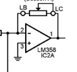
So, about the VC mix, I will need buffer the output and seems easy with this PCB bridechamber
and about the gain trims... maybe this that I found in Ken Stone website.- see picture attached- or maybe only a trim before the opamp.
So what buffer circuit can I put there?
| Description: |
|
| Filesize: |
7.7 KB |
| Viewed: |
43221 Time(s) |
|
|
|
|
Back to top
|
|
|
Sound
Joined: Jun 06, 2006
Posts: 842
Audio files: 1
|
| Posted: Sun Nov 02, 2008 2:55 am Post subject:
|
|
|
Ah! I see now!
If I put a buffer output like Mankato ones. Looking at the schematics, for example, the 12db Output, but I must to change the resistor R14 by a 100K trim resistor?
 |
|
|
Back to top
|
|
|
Sound
Joined: Jun 06, 2006
Posts: 842
Audio files: 1
|
| Posted: Sun Nov 02, 2008 3:08 am Post subject:
|
|
|
| Would work a 1K trim resistor + 1K output resistor,in the output of the U5A and before R43? |
|
|
Back to top
|
|
|
Funky40
Joined: Sep 24, 2005
Posts: 875
Location: Swiss
Audio files: 1
G2 patch files: 5
|
| Posted: Thu Nov 13, 2008 4:29 am Post subject:
|
|
|
Tim, is there a way to give the Mankato a sync/restart input ?
would be nice to syncronise it somewhat to clocks when using it as a VC-LFO. |
|
|
Back to top
|
|
|
Tim Servo
Joined: Jul 16, 2006
Posts: 924
Location: Silicon Valley
Audio files: 11
|
| Posted: Sat Nov 15, 2008 10:58 pm Post subject:
TH-201 "Mankato" PCBs available |
|
|
| Funky40 wrote: | Tim, is there a way to give the Mankato a sync/restart input ?
would be nice to syncronise it somewhat to clocks when using it as a VC-LFO. |
Hey Funk,
Hmm, I suppose you could do that. You would need to implement something like the typical FET driven by a very short pulse used for sync on many VCOs. The only problem is, you'd want to reset all four timing caps (330pF). It MIGHT work if you only reset the first cap (C4), but I'd have to try that one to really be sure. Actually, I've always thought sync on a VCF (while processing audio) would sound interesting, but I've never seen it tried anywhere. Might be a fun experiment, and you could look at VCO sync circuits to get a start.
Tim (syncing feeling) Servo |
|
|
Back to top
|
|
|
Tim Servo
Joined: Jul 16, 2006
Posts: 924
Location: Silicon Valley
Audio files: 11
|
| Posted: Sat Nov 15, 2008 11:28 pm Post subject:
|
|
|
| Sound wrote: | | Would work a 1K trim resistor + 1K output resistor,in the output of the U5A and before R43? |
Hey Sound,
Actually, what you want is a non-inverting buffer. Note that the buffer you've mentioned in the Mankato schemo in inverting. What I would do is run the CV Sum signal into a non-inverting buffer (maybe with a teeny bit of gain - something like 1.1) and then into a 1k trimmer and a 1k resistor like you mentioned. With that, you SHOULD be able to get the CV out to track with the internal CV. Whaddaya think?
Tim (non-inverting, except on Thursdays) Servo |
|
|
Back to top
|
|
|
Sound
Joined: Jun 06, 2006
Posts: 842
Audio files: 1
|
| Posted: Sun Nov 16, 2008 3:59 am Post subject:
|
|
|
Hi Tim, thanks again for your answer!
Finally I took the straight way. So I put the two mix out in the front panel through 1k resistor.
I think that for design a front panel you must understand the module, and you can mod it according your experience, your needed or interpretation of the module.
This thought stops me due I don't have enough experience nor knowledge for take these decisions.
So, instead design a definitive front panel with scaeffer, I took a piece of aluminum and made my own front panel that its provisional. I will investigate the Mankato behavior as well his CV. If in the future I want to change I just will do. Sure I will have more experience to take decisions.
I'm enjoying this experience very much and Im now mounting the front panel. Look the pictures.


 |
|
|
Back to top
|
|
|
Funky40
Joined: Sep 24, 2005
Posts: 875
Location: Swiss
Audio files: 1
G2 patch files: 5
|
| Posted: Sun Nov 16, 2008 8:09 am Post subject:
Re: TH-201 "Mankato" PCBs available |
|
|
| Tim Servo wrote: | | Funky40 wrote: | Tim, is there a way to give the Mankato a sync/restart input ?
would be nice to syncronise it somewhat to clocks when using it as a VC-LFO. |
Hey Funk,
Hmm, I suppose you could do that. You would need to implement something like the typical FET driven by a very short pulse used for sync on many VCOs.
Tim (syncing feeling) Servo |
ok, i see it is untestet, but it seems clear that it could be done.
that helps allready for further planning.
| Tim Servo wrote: | The only problem is, you'd want to reset all four timing caps (330pF).
|
i assume that the feeding is one wire to the each caps, or maybe two wires, one to each end of the cap, depending on Sync circuitry ?
right ?
( the VCO schematic i just look seems to feed the sync to each end of the cap )
Any danger to destroy something when lets say, taking the wrong sync circuitry ? 
Thank you Tim
| Quote: | | Tim (non-inverting, except on Thursdays) Servo |
| Quote: | | Actually, I've always thought sync on a VCF (while processing audio) would sound interesting, but I've never seen it tried |
hmmmm .... ??
what would that do ? |
|
|
Back to top
|
|
|
Sound
Joined: Jun 06, 2006
Posts: 842
Audio files: 1
|
| Posted: Sun Nov 16, 2008 12:54 pm Post subject:
|
|
|
| The standalone audio mixer doesn't work because If I cut the signal before R4 I cut also the resonance and the filter stop oscillating. OMG. |
|
|
Back to top
|
|
|
Appliancide*

Joined: Jul 04, 2007
Posts: 126
Location: Paul lives in a 1920’s film
|
| Posted: Wed Dec 03, 2008 5:29 pm Post subject:
|
|
|
Would there be adverse effects if I used silver mica for the 330pf and 560pf caps?
Thanks,
Paul
_________________
http://appliancide/blogspot.com |
|
|
Back to top
|
|
|
neandrewthal

Joined: May 11, 2007
Posts: 672
Location: Canada
|
| Posted: Thu Dec 04, 2008 1:23 am Post subject:
|
|
|
| *Appliancide* wrote: | Would there be adverse effects if I used silver mica for the 330pf and 560pf caps?
Thanks,
Paul |
Yes, you'd spend about a dollar more, each 
_________________
" I went through quite a few trannies til I found one I liked" - Wild Zebra |
|
|
Back to top
|
|
|
Appliancide*
Joined: Jul 04, 2007
Posts: 126
Location: Paul lives in a 1920’s film
|
| Posted: Thu Dec 04, 2008 5:31 am Post subject:
|
|
|
| neandrewthal wrote: | | *Appliancide* wrote: | Would there be adverse effects if I used silver mica for the 330pf and 560pf caps?
Thanks,
Paul |
Yes, you'd spend about a dollar more, each |
Ha! Well, I already have them, that's why I asked.
_________________
http://appliancide/blogspot.com |
|
|
Back to top
|
|
|
Tim Servo
Joined: Jul 16, 2006
Posts: 924
Location: Silicon Valley
Audio files: 11
|
| Posted: Thu Dec 04, 2008 9:22 am Post subject:
TH-201 "Mankato" PCBs available |
|
|
I would think it would sound just fine. I think the mica caps aren't quite as temp stable as the polystyrene units, but you most likely won't notice it. The 2164 chip seems to be VERY stable with temperature. Combine that with a 2k tempco, and you should notice very little difference, if any between mica and polystyrene caps. Go ahead and wire that puppy up!
Tim (not that I advocate connecting wires to puppies...) Servo |
|
|
Back to top
|
|
|
numbernone
Joined: Aug 16, 2006
Posts: 477
Location: new york city
|
| Posted: Sat Jan 03, 2009 3:16 pm Post subject:
|
|
|
Was plannning to put my second Mankato together soon. Have not really followed this thread since the first one ages ago, just been using it A LOT.
Where could I tap the circuit for a rate LED with a CGS board? Straight from the 0 degrees out? |
|
|
Back to top
|
|
|
Tim Servo
Joined: Jul 16, 2006
Posts: 924
Location: Silicon Valley
Audio files: 11
|
| Posted: Sat Jan 03, 2009 8:23 pm Post subject:
TH-201 "Mankato" PCBs available |
|
|
Hey Number,
You could tap a signal for a frequency indicator off any of the outputs. They'll all be at the same rate, just different phases. I would probably take the signal before the 1K output resistors, and would probably use the 0 degree out if you were going to have just one indicator. Since the LED driver circuit mentioned has a nice high input impedance, you could put one on each of the positive phases and have a nifty blinky light sequence. I built a bipolar indicator (each using an op amp and two LEDS) so I can see the negative and positive excursions. All sorts of possibilities, as long as you use a good driver circuit that doesn't load down the Mankato circuitry.
Tim (you never have enough blinky lights) Servo |
|
|
Back to top
|
|
|
glacial23
Joined: Apr 30, 2008
Posts: 32
Location: Cleveland, OH
|
| Posted: Mon Mar 08, 2010 10:10 am Post subject:
|
|
|
Are boards currently available? I sent an e-mail inquiry a couple of weeks ago about getting a PCB/SSM2164/tempco, but never got a reply.
_________________
glacialcommunications.com |
|
|
Back to top
|
|
|
wmonk
Joined: Sep 15, 2008
Posts: 529
Location: Enschede, the Netherlands
Audio files: 15
|
| Posted: Mon Mar 08, 2010 4:14 pm Post subject:
|
|
|
Same here, but my email was a week ago. I hope all is well. Can't wait to get the bucks to Magic Smoke 
_________________
Weblog! |
|
|
Back to top
|
|
|
mrmizuno1
Joined: May 22, 2007
Posts: 4
Location: Grand Rapids MI
|
| Posted: Wed Mar 17, 2010 12:31 am Post subject:
|
|
|
Uhhh yeah, I uhhh kinda sent 23.50 thinking they would be readily available and haven't heard back in about 10 days. uhhh partially my own darn fault but also wondering what the story is. I'd really rather not get PP involved and potentially hurting the credibility of Magsmoke... hrrmmm uhhhhh  |
|
|
Back to top
|
|
|
Tim Servo
Joined: Jul 16, 2006
Posts: 924
Location: Silicon Valley
Audio files: 11
|
| Posted: Wed Mar 24, 2010 5:37 pm Post subject:
TH-201 "Mankato" PCBs available |
|
|
Hi Everyone,
Sorry I've been so silent lately, but between moving with Tesla (my day job), my PC acting up, and my wife getting sick (2 - 3 weeks bed rest is her prescription), I've had a very busy month.
We've got a new batch of all our boards in stock, so we've got Mankato PCBs, along with 566 and XR VCO boards and "Cucamonga" VCLFOs. I've got a bunch of orders stacked up, so I'm catching up on those as quickly as I can. If you have an order with Magic Smoke and you're not sure of the status, give us a shout and we'll get everything straightened out ASAP.
We've also got some new stuff coming along. We're getting another test copy of Thomas' new DVD (have to make sure it plays on regular DVD players and not just PCs), and the Little Brother waveshaper clone is being tested and beat into shape for us by Harry Bissell as we speak. Once again, don't forget to scream at me if you have questions or need info. 
Tim (hoping April is a more 'boring' month) Servo |
|
|
Back to top
|
|
|
mattias

Joined: Jan 26, 2010
Posts: 28
Location: Cologne
|
| Posted: Tue May 18, 2010 11:18 am Post subject:
|
|
|
Tim,
are we still waiting for the tempcos, or was my shipment lost in transit while crossing the pond?
I'm OK with the first option, with the second not so much.
_________________
Red is black and plus is minus. http://www.bild-schall.com |
|
|
Back to top
|
|
|
Tim Servo
Joined: Jul 16, 2006
Posts: 924
Location: Silicon Valley
Audio files: 11
|
Posted: Tue May 18, 2010 2:11 pm Post subject:
TH-201 "Mankato" PCBs available
Subject description: TEMPCOS ARE HERE! |
|
|
Hey Mattias (and everyone else),
JUST got a big shipment of 2K tempcos in AND they're at a lower price!! If anyone is waiting for a Magic Smoke order with tempcos, we'll be getting those out in the next week or so. If anyone has an order WITHOUT tempcos that is otherwise late / missing / hung up / etc. please let me know. It's been very hectic (my day job at Tesla is TOTALLY busting my chops lately), so I apologize if anyone has been waiting a long time for stuff.
For people who are waiting for tempcos, the new prices are:
1 for $1.80, 2 to 5 for $1.50 each, 6 or more for $1.20 each
(plus shipping, of course).
If you're waiting for tempcos from us, drop me an email and let me know if you want a refund for the extra, or more tempcos to make up the difference (these new units are about half the price of the ones we had before). PCBs and 2164 chips are in stock, and we're ALMOST finished with the Lil' Bro waveshaper (a clone of the waveshaper from the ARP Little Brother). In fact, I'll have some Rev01 boards of the Lil' Bro available at a discount (they'll require some rework and an add on - more info once I have it all documented).
Once again, sorry for any delays, and send us some hate mail if you're waiting for products!
Tim (needs a clone of himself) Servo |
|
|
Back to top
|
|
|
mattias
Joined: Jan 26, 2010
Posts: 28
Location: Cologne
|
| Posted: Fri May 21, 2010 3:39 am Post subject:
|
|
|
Tim,
thanks for the update.
_________________
Red is black and plus is minus. http://www.bild-schall.com
Last edited by mattias on Thu Sep 23, 2010 11:22 am; edited 1 time in total |
|
|
Back to top
|
|
|
elanhickler
Joined: Jun 24, 2008
Posts: 152
Location: Gilbert, Arizona
Audio files: 3
G2 patch files: 6
|
| Posted: Wed Aug 18, 2010 1:36 pm Post subject:
|
|
|
DC vs AC inputs??
What is the disadvantage of having DC-coupled inputs when using AC current or audio waveforms? |
|
|
Back to top
|
|
|
Tim Servo
Joined: Jul 16, 2006
Posts: 924
Location: Silicon Valley
Audio files: 11
|
Posted: Wed Aug 18, 2010 4:24 pm Post subject:
TH-201 "Mankato" PCBs available
Subject description: DC or AC coupled inputs: The Eternal Question ;) |
|
|
| Argitoth wrote: | DC vs AC inputs??
What is the disadvantage of having DC-coupled inputs when using AC current or audio waveforms? |
Hi Arg,
(part of this response is copied from an earlier post here) Most VCFs have AC coupling for processing audio, and DC coupling for processing DC or very low frequency control voltages. Audio waveforms will sometimes have a slight DC bias or offset that makes them not perfectly symmetrical around 0V. This DC bias can result in a thump if a fast attack is used (this can happen with a VCF and/or a VCA). A DC bias can also change the results when several waves are mixed together. The AC coupling cap removes this DC bias.
The AC coupling cap does have an affect on the frequency response of the input. In most cases though, the cap is designed to cut frequencies below the audio range. If you're ONLY processing audio, then leave the AC coupling caps in place and you're all set. The Mankato has enough range however, that it can easily process DC control voltages. For that, you'll want to switch the coupling caps out of the signal path. You can use a Mankato as a voltage controlled Slew or Glide, and it's kinda fun to use it to slew the output of an LFO.
So the short answer: there's really no "disadvantage" to having DC coupled inputs (no coupling caps) on your VCF. Most synth signals will have little of no DC bias. You may run into this more if you process external signals a lot. It shouldn't cause any big problems, but it is something to be aware of.
As a side note, I just wanted to apologize to anyone who has been waiting for parts from Magic Smoke. Several personal things have come up recently, including some medical problems for my wife, and so my life has been very hectic over the last several months. Some orders have slipped longer than they should, but I just want people to know I am slowly catching up!
Tim (too much slew, not enough glide) Servo |
|
|
Back to top
|
|
|
|

 Forum index » DIY Hardware and Software » Thomas Henry designs


