| Author |
Message |
elmegil

Joined: Mar 20, 2012
Posts: 2179
Location: Chicago
Audio files: 16
|
 Posted: Sun Apr 28, 2013 6:07 pm Post subject: Posted: Sun Apr 28, 2013 6:07 pm Post subject:
|
  |
|
If you connect just the outer lugs, you have a resistor, not a pot.
I'm assuming you mean the rheostat connected pots; Thomas indicates these with a resistor with an arrow across it (for example Attack, Decay, & Release on the ADSR schematic). This means to connect one end and the wiper. It is common (you'll see it explicitly shown this way in other schematics) to tie the other end to the wiper. You're shorting that end of the pot anyway so it doesn't make any difference, but it keeps all the connections neat. And maybe there's some other reason to do it that I haven't gathered...
You may have to use some logic to determine which "end" to connect away from the wiper. Again using the ADSR example, you want the longest attack when your pot is turned fully clockwise, so you'd connect the counterclockwise lug and the wiper to get that effect (as I said, optionally connecting the clockwise lug to the wiper).
The logic is whether a higher resistance increases the parameter you're adjusting (like the attack) or decreases it (in which case you'd want the opposite, with the clockwise lug and the wiper instead). In all the ADSR examples, the higher resistance increases the time, so they all wire the same way. But for example, I have seen some VCOs where increasing the resistance lowers the frequency of the oscillator, in which case you want it wired the other way (assuming you want the "normal" counter clockwise is low frequency, clockwise is high frequency type of action). |
|
|
Back to top
|
|
 |
chieffrancis
Joined: Feb 07, 2013
Posts: 88
Location: california, united states
|
| Posted: Sun Apr 28, 2013 6:39 pm Post subject:
|
|
|
Okay so, if there is an arrow running through the pot, it will mean that only the 2 of the connections will be made, depending on the orientation you want.
But in most cases, the last end will be shorted with the wiper? Otherwise it's wired according to the schematic.
Thanks man, I'll have to see what I can do with the other pots for the other modules. |
|
|
Back to top
|
|
|
Thomas_Henry
Joined: Jul 24, 2009
Posts: 170
Location: N. Mankato, MN
Audio files: 3
|
| Posted: Sun Apr 28, 2013 7:20 pm Post subject:
|
|
|
Hello Elmegil,
| elmegil wrote: | | And maybe there's some other reason to do it that I haven't gathered... |
There is. If for any reason the wiper of the pot should fail to make contact with the resistive material, then at least you'll still have a resistor in place and not an open circuit. This usually makes no nevermind; the signal would simply not be passed and you'd know something was wrong. But if the rheostat was in the feedback loop of an op-amp, it could have major consequences (the amp would run open loop). A potentially harmful high level signal could be passed on, perhaps damaging your speakers or ears.
It's funny all the "best practices" we pick up early in life and just keep doing; I hadn't thought about this for years.
Thomas Henry |
|
|
Back to top
|
|
|
elmegil
Joined: Mar 20, 2012
Posts: 2179
Location: Chicago
Audio files: 16
|
| Posted: Sun Apr 28, 2013 7:44 pm Post subject:
|
|
|
Cool! Thanks for the explanation  |
|
|
Back to top
|
|
|
elmegil
Joined: Mar 20, 2012
Posts: 2179
Location: Chicago
Audio files: 16
|
| Posted: Sun Apr 28, 2013 7:52 pm Post subject:
|
|
|
| chieffrancis wrote: | Okay so, if there is an arrow running through the pot, it will mean that only the 2 of the connections will be made, depending on the orientation you want.
But in most cases, the last end will be shorted with the wiper? Otherwise it's wired according to the schematic.
Thanks man, I'll have to see what I can do with the other pots for the other modules. |
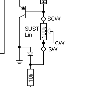
So here's a different schematic which shows what I'm talking about. Attack, Decay, and Sustain, all on the right side of the schematic, show the far lug shorted to the wiper explicitly. Whenever you see the arrow through the pot like in Analog Synth... you do the same thing. I normally wire them that way at the pot, soldering the two legs together or running the wire slightly longer and soldering to both lugs. |
|
|
Back to top
|
|
|
chieffrancis
Joined: Feb 07, 2013
Posts: 88
Location: california, united states
|
| Posted: Sun Apr 28, 2013 8:51 pm Post subject:
|
|
|
| elmegil wrote: | | So here's a different schematic which shows what I'm talking about. Attack, Decay, and Sustain, all on the right side of the schematic, show the far lug shorted to the wiper explicitly. Whenever you see the arrow through the pot like in Analog Synth... you do the same thing. I normally wire them that way at the pot, soldering the two legs together or running the wire slightly longer and soldering to both lugs. |
I hope you mean Release, rather than Sustain. But I get you, thanks for the info. |
|
|
Back to top
|
|
|
elmegil
Joined: Mar 20, 2012
Posts: 2179
Location: Chicago
Audio files: 16
|
|
|
Back to top
|
|
|
chieffrancis
Joined: Feb 07, 2013
Posts: 88
Location: california, united states
|
| Posted: Sun Apr 28, 2013 10:34 pm Post subject:
|
|
|
So you DO mean release then!  |
|
|
Back to top
|
|
|
elmegil
Joined: Mar 20, 2012
Posts: 2179
Location: Chicago
Audio files: 16
|
|
|
Back to top
|
|
|
chieffrancis
Joined: Feb 07, 2013
Posts: 88
Location: california, united states
|
|
|
Back to top
|
|
|
elmegil
Joined: Mar 20, 2012
Posts: 2179
Location: Chicago
Audio files: 16
|
| Posted: Mon Apr 29, 2013 5:39 pm Post subject:
|
|
|
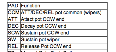
If that table were definitive, you'd only connect one piece of each of those other pots, which wouldn't do much good
I think that table has more to do with documenting the PCB than the schematic.... |
|
|
Back to top
|
|
|
chieffrancis
Joined: Feb 07, 2013
Posts: 88
Location: california, united states
|
| Posted: Mon Apr 29, 2013 8:03 pm Post subject:
|
|
|
But Sustain is the only one unlike the others? The symbols on the schematic are most similar between the A, D, and R...
Am I missing something? |
|
|
Back to top
|
|
|
elmegil
Joined: Mar 20, 2012
Posts: 2179
Location: Chicago
Audio files: 16
|
| Posted: Mon Apr 29, 2013 9:29 pm Post subject:
|
|
|
| All 4 of the pots have the CW leg of the pot tied to the wiper. I was just trying to cite a schematic using that notation rather than the arrow across the pot notation that Thomas uses. |
|
|
Back to top
|
|
|
chieffrancis
Joined: Feb 07, 2013
Posts: 88
Location: california, united states
|
| Posted: Mon Apr 29, 2013 10:29 pm Post subject:
|
|
|
However, the schematic differs from Thomas' Envelope because the Sustain's wiper is not directly shorted to either lugs..I think.
Thanks for the link though! |
|
|
Back to top
|
|
|
elmegil
Joined: Mar 20, 2012
Posts: 2179
Location: Chicago
Audio files: 16
|
| Posted: Mon Apr 29, 2013 10:37 pm Post subject:
|
|
|
| Oh, yeah. It's a totally different architecture, and in Thomas' ADSR, you're right, the Sustain is wired as a voltage divider, not a rheostat. |
|
|
Back to top
|
|
|
chieffrancis
Joined: Feb 07, 2013
Posts: 88
Location: california, united states
|
| Posted: Sun May 05, 2013 9:15 pm Post subject:
|
|
|
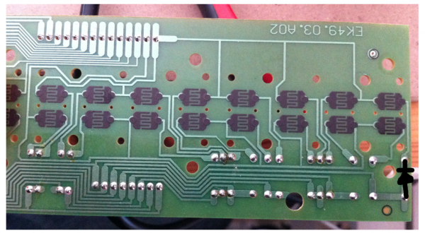
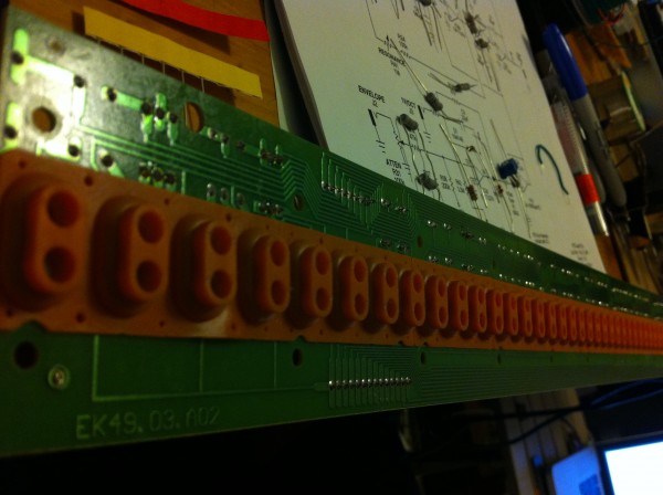
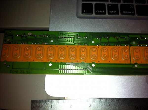
Hey guys, here's the underbelly of the keyboard. It seems to use the ROW/COLUMN configuration needed by the IKC to communicate with the modules, but I'm not sure exactly how to tell which side is ROW and which is COLUMN, or if I'm clearly mistaken and should cave in for a FATAR..
Geez the LFO is tough to get going haha.
Thanks for the help guys.
| Description: |
|
| Filesize: |
1.63 MB |
| Viewed: |
276 Time(s) |
| This image has been reduced to fit the page. Click on it to enlarge. |
|
| Description: |
|
| Filesize: |
1.65 MB |
| Viewed: |
293 Time(s) |
| This image has been reduced to fit the page. Click on it to enlarge. |
|
|
|
|
Back to top
|
|
|
elmegil
Joined: Mar 20, 2012
Posts: 2179
Location: Chicago
Audio files: 16
|
| Posted: Sun May 05, 2013 9:27 pm Post subject:
|
|
|
| I actually haven't built this LFO, I jumped straight to Thomas' CMOS LFO as it's 1) a newer design and 2) I could get PCBs from Fonik for it . Plus it doesn't use the 8038 which is harder to come by. |
|
|
Back to top
|
|
|
chieffrancis
Joined: Feb 07, 2013
Posts: 88
Location: california, united states
|
| Posted: Sun May 05, 2013 11:21 pm Post subject:
|
|
|
Yeah it's pretty long to build by hand with perf, I must admit as a beginner solder...er.
The most difficulat part of Thomas' designs are jumping the IC pins to different perfs, especially doing one board per page on a really small board.
Question about the output. The output is a typical mono out similar to that of other electrical instruments right? As in, in order to get the sound, I could either run it to an amplifier (probably use my bass amp since I don't have time to get a proper one) or plug it into an interface and record/playback audio from a DAW (i.e Ableton)?
I have to demonstrate it and turn in a user manual and comprehensive report including economic, political, social, and environmental impact (I believe the only applicable one would be social, but I've got open ears for ideas for my report ). I wonder if my teacher will dock me points for posting Thomas' designs into my report because I'm not about to take credit for copyrighted material, especially Thomas' as he has been instrumental in this DIY synth world.
PS. I hope you can give some insight on the keyboards, Bill  |
|
|
Back to top
|
|
|
elmegil
Joined: Mar 20, 2012
Posts: 2179
Location: Chicago
Audio files: 16
|
| Posted: Mon May 06, 2013 5:03 am Post subject:
|
|
|
| Yes, it's strictly a mono instrument. |
|
|
Back to top
|
|
|
chieffrancis
Joined: Feb 07, 2013
Posts: 88
Location: california, united states
|
|
|
Back to top
|
|
|
fonik

Joined: Jun 07, 2006
Posts: 3950
Location: Germany
Audio files: 23
|
| Posted: Mon May 06, 2013 3:01 pm Post subject:
|
|
|
in a diode matrix scanner keyboard the catodes are going to be summed into the rows, no?
so just follow the traces and compare it with the drawing on i.e. ray wilsons music from outer space scanning matrix keyboard page.
since the PCB of your keyboard is single sided it might look a little bit confusing at the 1st glance.
i would recommend to print out the drawing from MFOS and greenline it while following the traces on your PCB.
_________________

cheers,
matthias
____________
Big Boss at fonitronik
Tech Buddy at Random*Source |
|
|
Back to top
|
|
|
chieffrancis
Joined: Feb 07, 2013
Posts: 88
Location: california, united states
|
|
|
Back to top
|
|
|
elmegil
Joined: Mar 20, 2012
Posts: 2179
Location: Chicago
Audio files: 16
|
| Posted: Mon May 06, 2013 7:50 pm Post subject:
|
|
|
| Yes, the little rubber buttons in your keyboard are the switches in Ray's schematic. |
|
|
Back to top
|
|
|
chieffrancis
Joined: Feb 07, 2013
Posts: 88
Location: california, united states
|
| Posted: Tue May 07, 2013 1:23 am Post subject:
|
|
|
Okay so I guess the smaller row refers to the column connections as they are connected to the anodes of the diodes, so I shouldn't have a problem there since that would correspond to the exact number of input column pins on the IKC (8 pins) but here's where it gets confusing..
How am I to connect the row to the IKC if the IKC only has 8 input row pins but the keyboard has 14 pins? The diagram shows 5 rows for a 37 key.
Forgive me for the exhaustion and solder fumes may be preventing me to think straight lol |
|
|
Back to top
|
|
|
chieffrancis
Joined: Feb 07, 2013
Posts: 88
Location: california, united states
|
| Posted: Thu May 09, 2013 3:26 pm Post subject:
|
|
|
There's this little protrusion at the edge of my potentiometers that is preventing me from mounting it flat onto the panel..
Does anyone know what this protrusion's purpose is or how to prevent it from affecting the positioning? |
|
|
Back to top
|
|
|
|

 Forum index » DIY Hardware and Software » Thomas Henry designs