Joined: Jan 14, 2010 Posts: 5845 Location: Moon Base
Audio files: 709
Posted: Thu Sep 02, 2021 8:50 am Post subject:
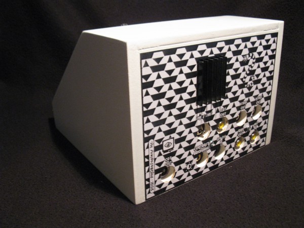
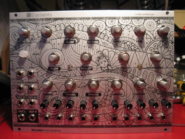
no knobs yet and not the best toner transfer ever but I finally have an Elements and it even works.
I only did a quick test but it has some nice sounds and can go quite orchestral.
Thank you very very much for the PCB Alan!
sorry it took so long to finish.
Elements - 01.jpg
Description:
Filesize:
367.69 KB
Viewed:
304 Time(s)
This image has been reduced to fit the page. Click on it to enlarge.
Posted: Tue Oct 05, 2021 4:57 am Post subject:
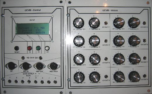
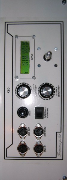
Formant Poly Demo Subject description: Short 3-voice polyphonic patch demo
Reactivated my Formant polyphonic synthesizer solution from the year 2004 and had a go at some old and nearly forgotten software bugs in my UCVM module and my poly keyboard
Joined: Jan 14, 2010 Posts: 5845 Location: Moon Base
Audio files: 709
Posted: Sun Nov 14, 2021 6:16 am Post subject:
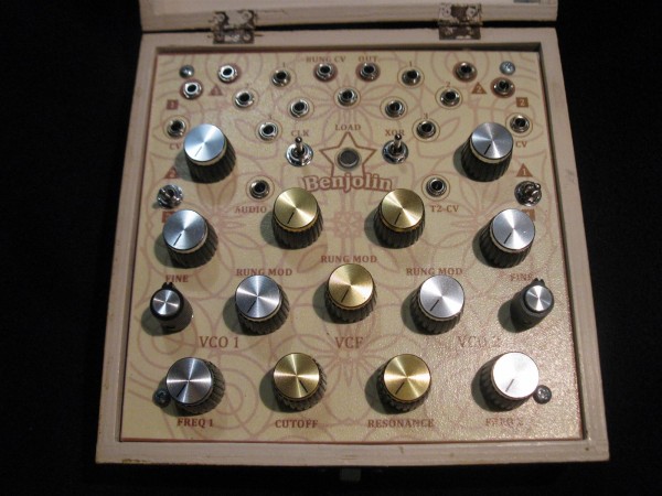
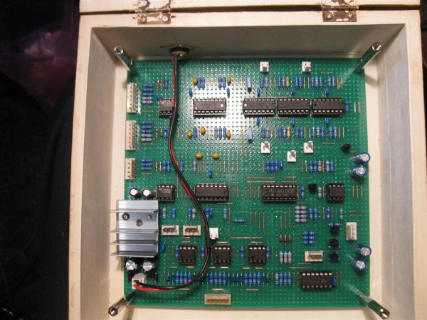
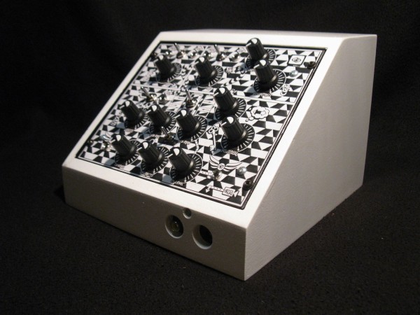
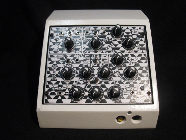
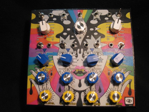
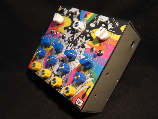
I finally have a Benjolin
Actually I finished it about 2 months ago and used it during the September Equinox concert and a recent halloween set,
but I mistakenly ordered only one knob of each type so had to wait untill I was ready to place another order.
Benjolin - 01.jpg
Description:
Filesize:
224.95 KB
Viewed:
254 Time(s)
This image has been reduced to fit the page. Click on it to enlarge.
Benjolin - 02.jpg
Description:
Filesize:
196.99 KB
Viewed:
256 Time(s)
This image has been reduced to fit the page. Click on it to enlarge.
Benjolin - 03.jpg
Description:
Filesize:
258.88 KB
Viewed:
262 Time(s)
This image has been reduced to fit the page. Click on it to enlarge.
Benjolin - 04.jpg
Description:
Filesize:
311.33 KB
Viewed:
255 Time(s)
This image has been reduced to fit the page. Click on it to enlarge.
Joined: Jan 14, 2010 Posts: 5845 Location: Moon Base
Audio files: 709
Posted: Mon Nov 29, 2021 7:41 am Post subject:
Thanks guys! have another one
The Phosterizer. a video posterizer effect which is a modified version of an Elektor Magazine video effect generator (June 1983 issue).
The enclosure used to be a bench power supply, hence the holes in the sides. I was thinking of covering it up with some wood but
I don't think it's worth wasting material and time on, it would just make it more bulky. Maybe I'll glue some thin black cardboard or
plastic on it. Connector and switch on the backside are a last minute addition so not labeled. Haven't been able to record it properly
as capturing and encoding makes it all kinds of blurry but you can find some earlier tests here and here.
VideoPhosterizer - 01.jpg
Description:
Filesize:
278.39 KB
Viewed:
155 Time(s)
This image has been reduced to fit the page. Click on it to enlarge.
VideoPhosterizer - 02.jpg
Description:
Filesize:
258.86 KB
Viewed:
153 Time(s)
This image has been reduced to fit the page. Click on it to enlarge.
VideoPhosterizer - 03.jpg
Description:
Filesize:
213.79 KB
Viewed:
160 Time(s)
This image has been reduced to fit the page. Click on it to enlarge.
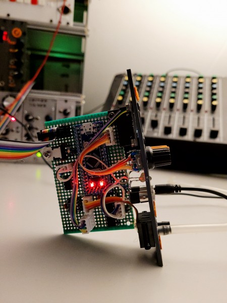
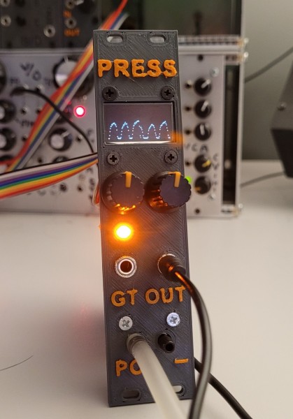
Wind controller.
A pressure sensor is read with a BluePill STM32, programmed with the Arduino IDE.
The waveform of the pressure is displayed on an Oled display.
the output is from a multiplying DAC, so with a potmeter I can set the amplitude, while with the rotary encoder I can set the offset, and by pressing the switch of the encoder, the output of the pressure sensor (I2C controlled) is calibrated to 0 volt out.
Also a gate is implemented, when pressure is applied, the gate goes HIGH, and goes LOW again when there is no more pressure measured.
About every 30mSec a measurement is taken.
press-side.jpg
Description:
Filesize:
748.38 KB
Viewed:
160 Time(s)
This image has been reduced to fit the page. Click on it to enlarge.
press-front.jpg
Description:
Filesize:
323.24 KB
Viewed:
169 Time(s)
This image has been reduced to fit the page. Click on it to enlarge.
Wind controller.
A pressure sensor is read with a BluePill STM32, programmed with the Arduino IDE.
The waveform of the pressure is displayed on an Oled display.
the output is from a multiplying DAC, so with a potmeter I can set the amplitude, while with the rotary encoder I can set the offset, and by pressing the switch of the encoder, the output of the pressure sensor (I2C controlled) is calibrated to 0 volt out.
Also a gate is implemented, when pressure is applied, the gate goes HIGH, and goes LOW again when there is no more pressure measured.
About every 30mSec a measurement is taken.
An Eurorack Module around the YMF704, this chip has GM midi on board and can play Wave-tables ánd FM-synthesis.
For now it's only playing Wave-Table sounds, but on the module there also is a BluePill that should be able to set the FM Synthesis parameters. _________________ my synth
Joined: Mar 28, 2006 Posts: 1438 Location: Kansas City, Mo USA
Audio files: 45
Posted: Sat Dec 18, 2021 4:55 pm Post subject:
Upgrade to vintage modules (updated)
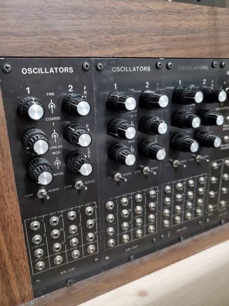
Has been a while since I've built anything new however my synthesizer has had a long-standing problem that I solved today.
The issue was I noticed distortion on the VCOs when tuned above 2500hz. At first I suspected a power supply issue but a quick check of the schematics indicated that the modules all had filter capacitors, etc.
However, the old oscillators' circuits did not include ferrite beads. So, I added ferrite beads in series with the power supply input on each module and happily the distortion disappeared. Indeed, the oscillator signals (most likely the square waves) were bleeding through the power supply buss.
Though I haven't built any new modules, I enjoy modifying the old ones to work better-than-new!
Update!
Well, I spoke too soon. Indeed, the ferrite beads helped however there was still bleedthrough.
I finally found the culprit! Turns out that in the Aries module designs, every square wave output -- from clocks, LFOs, and VCOs feeds a voltage divider (which in turn, feeds the output jack). The resistor values are relatively low (390 ohms and 1500 ohms). In other words, every square wave output was connected to the ground bus through a 1500 ohm resistor! Arrgh... my ground bus didn't stand a chance!
Anyway, I don't really see the need for a voltage divider and modified the output simply with a 10K protection resistor in series with the output jack and no feed to the ground bus. I know that 10K is a high value -- what it accomplishes is that this resistance reduces the load on the oscillator which, in turn, can pull down the power supply buss on the PCB and can be transmitted to the power supply busses.
I haven't done all the oscillators yet -- I started with the clocks. I have still to do the LFOs and will do the VCOs last. I suspect that I may need to mess with the values of the protection resistors on the VCOs but that remains to be seen.
I am not sure why Aries chose to run the square waves through voltage dividers (they didn't do this with other waveforms). I don't know why they chose such small resistance values for the voltage dividers. There were likely reasons that made sense in the 1970s that don't apply now with current technology.
Thanks for indulging me this long post. Details such as this make the difference between creativity and frustration. I have been fighting and working around this issue for a long time. Indeed, it was hard to feel creative when the tone of the VCOs was unsteady and harsh.
Ar-341Oscillators.jpg
Description:
Aries Ar-341 Voltage-controlled Oscillators
Filesize:
2.46 MB
Viewed:
151 Time(s)
This image has been reduced to fit the page. Click on it to enlarge.
Actually I finished it about 2 months ago and used it during the September Equinox concert and a recent halloween set,
but I mistakenly ordered only one knob of each type so had to wait untill I was ready to place another order.
Woaaaah, cool - any board layout by chance? I'll gite it a try on stripboard but maybe I'll turn mad doing this so any inspiration appreciated!
I'm not Forest Caver, but my understanding is he did get permission to release it this way.
Hey! Thanks for that - I already got all the schems and stuff (Euro-conversion...) but was especially interested in Phobos stripboard-/ veroboard-layout!
Joined: Jan 14, 2010 Posts: 5845 Location: Moon Base
Audio files: 709
Posted: Tue Feb 08, 2022 5:12 pm Post subject:
PERFORMANCE wrote:
Woaaaah, cool - any board layout by chance? I'll gite it a try on stripboard but maybe I'll turn mad doing this so any inspiration appreciated!
EDIT: Late to the 2021 party, I know, I know
It's pad per hole perfboard and the largest one I soldered to date. I'll see if I can post a layout but I design them with Sprint-Layout
which isn't the most convenient when it comes to sharing layouts, at least not the version I have. Note that I did add some mods to
the original benjolin circuit, inspired by casperelectronics, so I guess I schould upload the schematic aswell. _________________ "My perf, it's full of holes!" http://phobos.000space.com/ SoundCloudBandCampMixCloudStickney SynthyardsCaptain ColliderTwitchYouTube
You cannot post new topics in this forum You cannot reply to topics in this forum You cannot edit your posts in this forum You cannot delete your posts in this forum You cannot vote in polls in this forum You cannot attach files in this forum You can download files in this forum

 Forum index » DIY Hardware and Software


 and had a go at some old and nearly forgotten software bugs in my