| Author |
Message |
-minus-
Joined: Oct 26, 2008
Posts: 787
Audio files: 13
|
 Posted: Sat Jan 16, 2010 11:20 am Post subject: Posted: Sat Jan 16, 2010 11:20 am Post subject:
|
  |
|
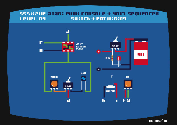
Finally.... Got the vero/stripboard diagrams done. Maybe if I played around with it more, it could fit into a smaller footprint... but I have built and tested this, and it works fine... far as I can tell. I changed the LED resistors from 80K to 18K as the bulbs weren't burning too brightly. Also I have added an on/off LED and switch. Admittedly I don't have the LDR connected to my build yet, but I think the diagram is correct...
| Description: |
|
| Filesize: |
496.11 KB |
| Viewed: |
1171 Time(s) |
| This image has been reduced to fit the page. Click on it to enlarge. |

|
| Description: |
|
| Filesize: |
411.13 KB |
| Viewed: |
1373 Time(s) |
| This image has been reduced to fit the page. Click on it to enlarge. |
|
| Description: |
|
| Filesize: |
512.32 KB |
| Viewed: |
1361 Time(s) |
| This image has been reduced to fit the page. Click on it to enlarge. |

|
| Description: |
|
| Filesize: |
683.78 KB |
| Viewed: |
1099 Time(s) |
| This image has been reduced to fit the page. Click on it to enlarge. |

|
| Description: |
|
| Filesize: |
648.77 KB |
| Viewed: |
2885 Time(s) |
| This image has been reduced to fit the page. Click on it to enlarge. |

|
|
|
|
Back to top
|
|
 |
-minus-
Joined: Oct 26, 2008
Posts: 787
Audio files: 13
|
| Posted: Sat Jan 16, 2010 11:28 am Post subject:
|
|
|
For some strange reason, the images are in reverse order... 
I've never posted images before... I previewed them... but they seemed to appear in reverse order... so I reloaded them in reverse hoping they would come out the right way... but no!
Don't worry about me.... just a bit confused...  |
|
|
Back to top
|
|
|
airfrankenstein
Joined: Jan 10, 2010
Posts: 62
Location: france
|
| Posted: Sun Jan 17, 2010 1:45 am Post subject:
|
|
|
Hey Minus those are some very cool layouts !
By reverse order I take it you mean the levels and not the images themselves ?
Did you do your build on stripboard btw ?
cheers |
|
|
Back to top
|
|
|
-minus-
Joined: Oct 26, 2008
Posts: 787
Audio files: 13
|
| Posted: Sun Jan 17, 2010 8:22 am Post subject:
|
|
|
Yeah, built it on stripboard.... NO PROBLEMS with the diagram. What I meant was that I wanted the top image to come last, and vice versa. Just being a bit picky! Might be using this method of oldskool atari art for future stripboards seeing I have a lot of the components drawn up in Illustrator now.
Got the device cranking at a fast rate as I type! That 1K resistor to the 1M pot seems to do the job ok. Just been seeing how much I can reduce the value and get it not to cut out.
Was wondering... I have found that in general that with the 100K pots, about two thirds of the rotation has no sound at all. What are your, or other builders experiences here? I'm wondering what can be done about this. It seems we have a little range to use on these pots. The last third of a clockwise turn is the only part which works! I wonder if a smaller pot value would change this, or am I barking up the wrong tree? Maybe a resistor needed in conjunction with the pot somewhere? Or a larger pot???
I might have to do a bit of experimenting here...
Any ideas?
Anyone?
Thanks! |
|
|
Back to top
|
|
|
-minus-
Joined: Oct 26, 2008
Posts: 787
Audio files: 13
|
| Posted: Sun Jan 17, 2010 8:53 am Post subject:
|
|
|
ALSO... and sorry for filling this forum up with reams of crap....
I have just been playing around with reducing the value of the 8 resistors going to the LED's which indicate the steps. I suggested that 18K was ok. I have been trying 10K and getting a little more brightness. The trade off here is you notice a lowering of tone when you connect the led. Not really a problem though as the highest pitch note doesn't seem adversely altered. The general rule seems to be, the lower the value of resistance, the brighter the LED. But I guess it's 'sucking' a bit more off the available power (current? voltage?) not sure what you'd call it, from the pot... Well, looks like it's taken me a year to learn or begin to understand what these little stripey things called resistors might be doing!!! Takes me a while to learn anything these days  |
|
|
Back to top
|
|
|
airfrankenstein
Joined: Jan 10, 2010
Posts: 62
Location: france
|
| Posted: Sun Jan 17, 2010 8:56 am Post subject:
|
|
|
regarding the 100k pots my impression is that the whole range affects the sound but perhaps less in terms of pitch than in terms of step. have to experiment some more and will get back with a more conclusive report.
otherwise this thing really grooves! |
|
|
Back to top
|
|
|
-minus-
Joined: Oct 26, 2008
Posts: 787
Audio files: 13
|
| Posted: Sun Jan 17, 2010 9:15 am Post subject:
|
|
|
HMMM.... I find that the first two thirds of a clockwise turn is doing nothing. I get no sound on that step at all. It seems to take to about '2 o'clock' on the pot dial for the low deep rumbling clicking APC sounds to kick in. It is a fun thing to play with though! I want to put a switch in this circuit so we can manually pulse through each step and tune each note before we start the sequencer running. Also a on/off switch on each step might be useful... although with my 100K's having a good 2/3rds of a blank spot on them, this may not be necessary 
Looking forward to the results of your research into this very important field of Atari Punkology! |
|
|
Back to top
|
|
|
airfrankenstein
Joined: Jan 10, 2010
Posts: 62
Location: france
|
| Posted: Mon Jan 18, 2010 11:31 pm Post subject:
|
|
|
atari punkology...my impression now is that the pots have more effect on the sound as you increase the pitch. Anyone know for sure ?
Also Minus, did you figure out how to wire a rotary switch up to select the number of steps. I've got a 4p3T I'd like to try but I'm having a hard time understanding the science. |
|
|
Back to top
|
|
|
fonik

Joined: Jun 07, 2006
Posts: 3950
Location: Germany
Audio files: 23
|
|
|
Back to top
|
|
|
fonik
Joined: Jun 07, 2006
Posts: 3950
Location: Germany
Audio files: 23
|
| Posted: Tue Jan 19, 2010 2:26 am Post subject:
|
|
|
| -minus- wrote: | | The general rule seems to be, the lower the value of resistance, the brighter the LED. But I guess it's 'sucking' a bit more off the available power (current? voltage?) not sure what you'd call it, from the pot... |
the general rule is called 'Ohm's Law':
I=V/R or
Current=Voltage/Resistance or
Ampere=Voltage/Ohm
a LED is driven by current. resistor in front or behind a LED converts the voltage into current, and according the law above you are right: the lower the ristance, the higher the current, thus the brighter the LED.
BTW a CMOS provides only limited current, so for stable operation it would be better to buffer the outputs, but i think that's not what you necessarily wanted to do with a badass punk console!?
maybe you could try super bright LEDs? then you would need less current for driving the LEDs (using higher resistance). additionally you could try using 500k pots or even 1M to reduce the current draw from the 4017...
_________________

cheers,
matthias
____________
Big Boss at fonitronik
Tech Buddy at Random*Source |
|
|
Back to top
|
|
|
airfrankenstein
Joined: Jan 10, 2010
Posts: 62
Location: france
|
| Posted: Tue Jan 19, 2010 7:44 am Post subject:
|
|
|
| thanks for your help fonik ! |
|
|
Back to top
|
|
|
airfrankenstein
Joined: Jan 10, 2010
Posts: 62
Location: france
|
Posted: Wed Jan 20, 2010 12:09 pm Post subject:
Subject description: rotary switch question again |
|
|
| sorry if this sounds dumb but I'm about to put a rotary in and i just want to be sure i've understood correctly: I take the wire running from the 4017 to one of the pots for example and solder on another wire going from the same pot to the appropriate position on the rotary ? |
|
|
Back to top
|
|
|
fonik
Joined: Jun 07, 2006
Posts: 3950
Location: Germany
Audio files: 23
|
| Posted: Wed Jan 20, 2010 2:42 pm Post subject:
|
|
|
yes.
_________________
cheers,
matthias
____________
Big Boss at fonitronik
Tech Buddy at Random*Source |
|
|
Back to top
|
|
|
airfrankenstein
Joined: Jan 10, 2010
Posts: 62
Location: france
|
| Posted: Sun Jan 24, 2010 3:12 pm Post subject:
|
|
|
| just a quick question...could the individual 80k resistors on the leds be replaced by something like just one 470k resistor on the first led ? |
|
|
Back to top
|
|
|
-minus-
Joined: Oct 26, 2008
Posts: 787
Audio files: 13
|
| Posted: Sun Jan 24, 2010 11:49 pm Post subject:
|
|
|
My immediate impression is that it wouldn't work. I assume you mean the wire going from pin 1 of the clock 555? And after the 1K resistor going to the pulse rate led? I think this would affect the sound on all 8 of the 100K pots. I have used 18K resistors on all 8 LED's which has made them burn brighter.
I am going to try what fonik mentioned about using super bright LED's. They are more expensive, but probably worth it. You could just buy 1 and test it before buying 8!
Good luck! I won't be able to look at this until next week! |
|
|
Back to top
|
|
|
airfrankenstein
Joined: Jan 10, 2010
Posts: 62
Location: france
|
Posted: Mon Jan 25, 2010 8:30 am Post subject:
Subject description: sequencer bleed-through |
|
|
There is one very odd thing happening.
I'm running the sequencer through a daisy chain 9v power supply for multiple effects and the sound seems to bleed over the power line.
I have a dual oscillator on this daisy chain and even if I unplug the output of the sequencer the sound plays through the oscillator!!! Any idea what's happening ? Is this normal ? Does it have something to do with the diodes ?
Hope someone can help. |
|
|
Back to top
|
|
|
-minus-
Joined: Oct 26, 2008
Posts: 787
Audio files: 13
|
| Posted: Thu Jan 28, 2010 5:59 am Post subject:
|
|
|
Airfrankenstein: I'm wondering if a power diode on your (+) power supply might stop this? But then again I'm a bit of a novice... maybe someone else might know?
I have just tried wiring the 500K and 1M pots differently. Not a big change... just took the wire going to the left tab and re-soldered it to the right tab. To me the pots seem to respond in reverse to what I'd think was logical. Now when I turn the 500K clockwise, the tone gets higher. And with the pulse rate on the 1M pot, when I turn it clockwise, the rate gets faster.
I still have the two thirds of the eight 100K pot unusable problem. About to experiment with 500K pots and 1M pots to see if I can push that unusable portion back to a bare minimum. Will post findings soon.
Oh yeah, discovering some interesting 'bends' along the way. Will share once scientific study is complete! 
One more thing: Anyone have any ideas about making more distinctive bleeps on each step? At the moment if the eight pots are all the same setting, the tone becomes one long tone if you know what I mean... Nice to get short gaps between each. Am I needing transistors here? Or small capacitors?  |
|
|
Back to top
|
|
|
-minus-
Joined: Oct 26, 2008
Posts: 787
Audio files: 13
|
| Posted: Thu Jan 28, 2010 6:52 am Post subject:
|
|
|
OK... The 500K pot didn't do much so I tried a 5K pot. Nope... There is a problem here. Why is the first two thirds (or more) of the pot blank in terms of sound??? Maybe a resistor along the (-) wire to the 8 pots might do it?
I've tried 2 coffees, 5 cigarettes, and a 500K pot...
Then tried a 5K pot, 2 cigarettes... so maybe 500 coffees would help?
No wait! What about 500 cigarettes, 5 coffees, and a 2K pot?
Hmmm... the cigarettes? In series... or parallel?
Anybody?
 |
|
|
Back to top
|
|
|
airfrankenstein
Joined: Jan 10, 2010
Posts: 62
Location: france
|
| Posted: Thu Jan 28, 2010 7:07 am Post subject:
|
|
|
no light at the end of the tunnel here either minus.
I'm experiencing the same frustration with the tone pots. you're right - there seems to be very little variation in pitch.
My pots too work kind of backwards, but for that moment I can live with that.
I did get the rotary in which makes things alot more interesting plus the on/off switches on each step which is also quite efficient.
tried the IK between speed pot and pin 8 of 555 clock but now for some reason the sequencer just goes blip blip blip...
here we go again... |
|
|
Back to top
|
|
|
-minus-
Joined: Oct 26, 2008
Posts: 787
Audio files: 13
|
| Posted: Thu Jan 28, 2010 7:18 am Post subject:
|
|
|
MY MISTAKE!
...the 500K pot did perform differently! Lack of sleep caused me to rewire the 100K pot I had removed back on... Yes, with the 500K pot I am getting a full sweep with the rotation. However, most of the tonal difference seems to be at the fully clockwise end. This seems the case with the stand alone APC come to think of it.....
This noise device is seriously p*ssing off my ex whom I am staying with whilst visiting my son... I have been moved outside and I am now hand wiring on the back step under moonlight! A good sign actually... bad noise is good noise! Might have to wait until sun up to retest with all eight pots at 500K.
The 100K thing did have me wondering you know. The original APC I built did have two 500K's...
Blah, blah.... |
|
|
Back to top
|
|
|
airfrankenstein
Joined: Jan 10, 2010
Posts: 62
Location: france
|
| Posted: Thu Jan 28, 2010 7:51 am Post subject:
|
|
|
cool.
I might give it a try as well.
It's up and running again, lack of sleep here as well, I pulled the pin 15 wire off the rotary whence the blips.
I might try running the sequencer with a sine wave generator to see if that makes any difference regarding pot sweeps.
Nobody here apart from myself seems keen on the sequencer. such is life.
sign me somewhere between a werewolf and a zombie.
cheers |
|
|
Back to top
|
|
|
-minus-
Joined: Oct 26, 2008
Posts: 787
Audio files: 13
|
| Posted: Thu Jan 28, 2010 6:45 pm Post subject:
|
|
|
Ha ha! I'm of the belief I must have VAMPIRE in my genes.
Look, now I'm not sure about the 500K swap... I have tried so many combinations I'm not sure what works anymore. A recent discovery is that by cutting the wire from pin 1 of the clock 555.... the wire which goes to the pulse LED and resistor.... the pulse LED burns less brightly, but the pay off here is that the 100K pots have more of a usable range to them. I'm thinking that by using those super bright LED's which are more efficient, this will open up the sweep range and still have reasonably bright LED's. Testing need to be done here! ...but need to return home on sunday first (back to my castle in Transylvania) to source parts.
I really can't understand why nobody seems to like this sequencer other than ourselves? Perhaps it is only something demons of the night appreciate. Maybe thats why we are not hearing the frequencies on the pots? Perhaps if we were human we would understand why nobody likes it! I think every home should have at least one. And they should be kept on at all times... like a refrigerator! |
|
|
Back to top
|
|
|
airfrankenstein
Joined: Jan 10, 2010
Posts: 62
Location: france
|
| Posted: Thu Jan 28, 2010 11:59 pm Post subject:
|
|
|
We've got two now in our home.
Keep us posted about your test with the super brights. I'm off for a week. |
|
|
Back to top
|
|
|
airfrankenstein
Joined: Jan 10, 2010
Posts: 62
Location: france
|
| Posted: Sun Feb 07, 2010 6:52 am Post subject:
|
|
|
| maybe a tapered pot or a log pot would work better. I think you can try putting a resistor across pins 1 and 3 of the pot. |
|
|
Back to top
|
|
|
blue_lu
Joined: Nov 16, 2009
Posts: 32
Location: Germany
|
| Posted: Sun Feb 07, 2010 3:10 pm Post subject:
|
|
|
Hi,
another Euro dude here. Just wanted to let you know that I am reading all this with great interest as I have dreamed about something like this since I build my first atari punk console kit.
speaking of get lofi they sell kits for a 555 clock, 4017 Sequencer too - anyone tried to hook these up with the apc kit?
of course doing it yourself on vero/perf board is the real deal... I am watching and will attempt to build this in late february (stupid uni exams,heh). |
|
|
Back to top
|
|
|
|

 Forum index » DIY Hardware and Software